Optimizing Performance of Subcarrier
Assignment and Power Allocation for
OFDMA Systems
Aswini.M.G1, Ashokkumar.M2
PG Scholar, Department of ECE, Adhiyamaan College of Engineering, Hosur, Tamilnadu, India1
Assistant Professor, Department of ECE, Adhiyamaan College of Engineering, Hosur, Tamilnadu, India2
ABSTRACT: Cooperative communication has recently been considered as a key technology for modern wireless standards and next generation wireless networks to improve the quality-of-service (QoS) and extend transmission coverage in a cost-effective manner. For designing the efficient OFDM-based relay communication systems, there are various relaying schemes are used. Among these schemes amplify-and-forward (AF) and decode-and-forward (DF) schemes are considered and adaptive relaying protocol has been proposed to improve the performance of Subcarrier assignment and power profiles with multiple users using orthogonal frequency division multiple access (OFDMA).The objective is to allocate subcarrier for band separation of channel to carry the bits of information at stable power level. We formulate such a problem as a subcarrier based resource allocation that seeks joint optimization of subcarrier pairing, subcarrier-pair-to-relay assignment and power allocation. Simulation result demonstrate the proposed method give better performance when compared with the conventional techniques in terms of SNR and BER.
KEYWORDS: AF/DF cooperative communication, Power allocation,Adaptive Relaying Protocol
I. INTRODUCTION
In wireless relay networks (WRNs) signals are transmitted from one terminal to another through a number of relays. The main advantage of doing so is a reduced signal transmit power. As multiple users come into play, efficient management of relay resources becomes a critical issue for improving the system performance. In [1], the authors developed power allocation schemes for AF multi-user system using different objectives such as maximizing the minimum rate, maximizing the sum rate, and minimizing the total power consumption with a constrained minimum transmission rate. In [2], the authors studied relay assignment and power allocation for AF relay system to maximize the sum-rate of all users subject to individual and total power constraints.
Resource allocation in OFDMA systems is a complex problem, especially in the uplink communication due to the following reasons: the discrete nature of the subchannel assignment, the heterogeneity of the users’ subchannel conditions, and individual resource constraints. Compared to conventional OFDMA transmission, relay-aided (cooperative) OFDMA transmission raises more complicated resource allocation problems as it introduces extra tasks. Such tasks are: deciding the transmission mode of each subcarrier, and determining the assisting relays and power assignment for each subcarrier at the source and relay nodes under individual and total power constraints [16]-[19].
Time sharing principle is one of the approaches which is used to solve mixed-integer resource allocation problems in OFDM and OFDMA systems [20]. In practical OFDMA systems, the duality gap goes asymptotically to zero for small number of subcarriers as shown in [17]-[22]. Sub-optimally approaches for resource allocation in OFDMA systems are investigated as in [23], where a two-phase approach is proposed; the subcarriers are assigned in the first phase using a genetic algorithm based on equal power allocation, then optimal power allocation is performed in the second phase. Resource allocation for OFDMA with cooperative communication was investigated in many works such as [24]-[26].
An adaptive relaying protocol (ARP) is proposed here, which takes advantages of both DF and AF protocols and minimize their disadvantages. For the proposed scheme, all relays are included into one of two relay schemes, which we called a DF relay scheme, and an AF relay scheme. All relays, which can correctly decode the signals transmitted from the source, are included in the DF relay scheme and the rest of relays, which fail to make a correct decoding, are included in the AF relay scheme.
All the relays in the AF relay scheme amplify the received signals from the source and forward it to the destination, while the relays in the DF relay scheme decode the received signals, re-encode and forward them to the destination. Another important feature is that the processing at relays and destination for the ARP scheme in a practical application is that the relay can automatically adapt to the channel quality by simply switching between the AF and the DF without any need for the channel state information (CSI) to be fed back from the destination to the relays or the source. The processing at the destination for the ARP is the same as for the AF and DF.
All signals received at the destination, forwarded from the relays in both the AF and DF schemes are combined together into one signal. The performance of the proposed ARP is analyzed and compared with other relaying protocols. It is shown that the proposed ARP scheme considerably outperforms the AF scheme and circumvents the error propagation due to the imperfect decoding at relays in a DF protocol, thus considerably outperforming both the AF and the DF protocols. This performance gain grows as the number of relays increases and it approaches the perfect DF at the high signal to noise ratios (SNR). The above analytical results are also validated by simulation results.
Rest of the paper is structured as follows. Section II describes the system model. Section III-V describes different relaying protocols. The Performance analysis is presented in Section VI. Numerical results are presented and discussed in Section VI. Section VIII concludes this paper.
II. SYSTEMMODEL
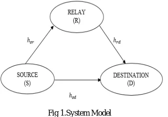
A simple cooperative communication system is considered in this work and simulated in Matlab. Fig. 1 gives a block diagram of a 2-hop relay system consisting of one source, relay and one destination with a direct link from the source to the destination. We assume that the source and relays transmit data through orthogonal channels. In the separate time slots, the source and relays transmits the information to the destination. The source first broadcasts the information to both the destination and relays. The source node and destination node are fixed so distance between them is constant, while relay node is moved over various points between source node and destination node, starting from near to source node to near to destination node. Signal is sent by transmitting node to destination node and relay node. The relay node performs operation of amplify and forward and decode and forward on the received signal, separately. Then operated signal at relay node is forwarded to destination, so destination will have two copies of the same signal, one direct signal (from transmitting node) and another operated signal (from relay node). Two signals are combined at the destination to get a stronger signal and then BER (bit error rate) of combined signal is calculated over fixed SNR (signal to noise ratio) value. The performance of each technique AF and DF is analyzed against BER. Different graphs are generated over different SNR values to show location impact of relay node on AF and DF’s performance. The received signals at the relay i and destination, at time k, denoted by ,( ) and ( )respectively, can be expressed as
where s(k) is the symbol transmitted at time k, , = . , , = . ( ) are the received signal power at the relay i and destination, respectively, is the source transmit power, ,and are the channel gains between the source and relay i and that between the source and destination, respectively. Alsoℎ ,and ℎ are the fading coefficients between the source and the relay i and between the source and destination, respectively [5].
Fig 1.System Model
In this paper, we consider the fading coefficients are constant within one frame and change independently from one frame to another. Furthermore, ,( ) and ( )are zero mean complex Gaussian random variables with power spectral density of /2 per dimension. The relays then process the received signals and send them to the destination [5]. Let ,( ) represent the signal transmitted from the relay i at time k. It satisfies the following transmit power constraint,
,( ) ≤ , (3)
where , is the transmitted power limit at the relay i. The corresponding received signal at the destination at time k, denoted by ,( ) , can be written as
,( ) = ,ℎ , ,( ) + ,( ) (4)
where is the channel gain between the relay i and destination,ℎ , is the fading coefficient between the relay i and destination and ,( ) is a destination noise with power spectral density of N0/2 per dimension.
III. AMPLIFYANDFORWARD(AF)
As the name shows, the Amplify and Forward relaying technique simply amplify the signal received by the relay and forward it to the destination [3]. This method is better to use when the relay has only limited computing time and power available, or the time delay caused by the relay to perform operation on the received signal, which has to be minimized [4]. The working principal of amplify and forward relaying protocol is very simple. The signal received by the relay node must be attenuated and needs to be amplified before it can be sent again towards destination. While amplifying the received signal the noise in the signal is also amplified, this is the main drawback of this technique. Another disadvantage of this technique is that it is not able to store any information in a buffer as the processing involved is analogue but not digital.
An AF relaying scheme, denoted byΩ , consists of all the relays, which could not decode correctly [5]. Upon receiving signals from the source, each relay in the AF relay scheme will simply amplify the received signals from the source. Let ,( ), Ω represent the signal transmitted from the relay i at time k, then it can be expressed as
,( ) = ,( ), Ω (5)
= ,
, ,
(6)
By substituting (5) and (1) into (4), the received signal at the destination, transmitted from relay i become
,( ) = ,ℎ , ,ℎ , ( ) + ,( ) + ,( ), Ω (7)
IV. DECODE AND FORWARD (DF)
This is the most preferred technique for processing the signal received by relay node. Working principal of decode and forward relaying protocol is closest to the one of a conventional relay. The working principal behind decode and forward is that the received data in relay node is decoded first and then it is transmitted to destination after reencoding[3]. If an error correcting code is placed with source message, bit errors in received data could be corrected at the relay node. And if no error correcting code is given in source data then a checksum makes relay node capable of detecting if the received data has errors or not. Now it depends on the implementation that a message with errors should be forwarded to destination or not.
The DF relaying scheme, denoted byΩ , consists of all the relays, which can make an error-free decoding [5]. Since all the relays in the DF relay scheme can decode correctly, each relay in the DF relay scheme can accordingly recover the binary information stream is then encoded and modulated into S. The relay i in the DF relay scheme will then forward the modulated symbols S with power , to the destination,
,( ) = , ( ), Ω (8)
The received signals at the destination, transmitted from the relay i in the DF relay scheme, become
,( ) = ,ℎ , , ( ) + ,( ), Ω (9)
V. ADAPTIVE RELAYING PROTOCOL (ARP)
For the proposed adaptive relaying protocol (ARP), in each transmission, based on whether relays can make correct decoding or not, each relay is included into one of two schemes, an AF relay scheme and a DF relay scheme.All the relays in the AF relay scheme amplify the received signals from the source and forward it to the destination, while all the relays in the DF relay scheme will decode the received signals, re-encode and forward them to the destination. This is a new method given in this work. As relay node moves between source and destination no single relaying strategy can give constant results and at some points cooperation is no more useful, so if two relaying techniques are used together could result in a better performance. According to this method a relay station will be equipped with more than one relaying strategies and relay station will be capable of switching between different relaying techniques, according to its location relative to source and destination. This could mitigate location effects on the performance, while relay is moving all around. When a relay station is loaded with more than one relaying technique and it is enough intelligent to trace its own location, and it can switch between different relaying techniques according to its location.
For example if we consider a relay station which is equipped with AF and DF and it is capable of locating itself and multiplex between two relaying techniques. In such a scenario whenever the information is more it will use DF, once it is less it will switch to AF. In doing so the user (source) can enjoy the benefits of cooperation throughout the whole transmission, even though relay node is moving all around. Below are graphs generated over different SNR values to show this method is useful. All signals received at the destination, forwarded from the source, the AF and DF schemes, are combined as follows,
The optimal values of and , are given by
= ∗ , , = ,
∗
, Ω , , =
, , ∗ , ∗,
, ,
, Ω (11)
By substituting (11) into (10), the destination SNR after combination, denoted by , can be approximated as
= + (12)
where = |ℎ | + ∑ Ω (13) =∑ Ω , ℎ , (14)
where = , , = , , , = , , is called the Harmonic Mean of variables
VI. PERFORMANCE ANALYSIS
In this section, we analyze the performance of the ARP and compare with other relaying protocols. For simplicity of calculation, we assume that , = and , = for all i=1,….n.Let and represent the instantaneous received SNR of the combined signals in the AF and DF relay schemes.
= |ℎ | + ∑ (15) = ∑ ℎ , (16)
Due to the uniform distribution of relays and assumption of , = for all i=1….n. the average PEP at high SNR, denoted by ( ), can be calculated as
( )≤ ∑ ∏ , ℎ , ∏ 1− , ℎ , 2 + 2 (17)
At high SNR, ( )≤ ( ) 1 + (18)
Similarly, for a perfect DF, in which all relay are assumed to decode correctly, the average PEP of incorrectly decoding to a code word with weight d, denoted by ( ), can be calculated as
( )≤ ( ) (19)
Eq. (18) can be expressed as, ( )≤ 1 + ( ) = ( ) (20)
where = 1 + > 1 (21)represents the performance loss of the ARP compared to the
DF. Let be the average upper bound on the bit error rate (BER) for the ARP. At high SNR, it can be approximated as
≈ ∑ ∑ ( | ) ( )(22)
where is the number of words with Hamming weight j and ( | ) is the probability that an input word with
Hamming weight j produces a code word with Hamming weight d.
Similarly analysis, the average PEP of the AF of incorrectly decoding to a code word with weight d, denoted by ( ), can be similarly calculated as
( ) = 2 , ≤
1
Compared to ( ), the average PEP of the ARP in Eq. (18) can also be expressed as
( )≤ / ( ) (23)
where / = 1− ∅( ) < 1 (24) represents the performance gain of the ARP over the AF.
The power allocated to a sub-channel or the transmit power in each sub-channel , having power gains ℎ
with the water level of user i, = +∑ is
, = +∑ − + ∑ − (25)
The data is generated randomly and then modulated by 16 bit, 32 bit and 64 bit QAM modulation schemes to obtain BER performance of the OFDM system.
VII. SIMULATIONRESULTSANDDISCUSSION
In this section, we provide simulation results comparisons for various relaying schemes. Fig. 2 compare the performance of the AF, the ARP and the DF for different SNR Valuesover 1000 iteration. It can be noted that the ARP significantly outperforms the AF in all SNR regions, and perform very close to the perfect DF as increases. It can be noted from Eq. (24) that / is a decreasing function of , therefore, as either or n increases, / is exponentially decreasing, and the ARP can achieve considerable performance gain compared to the AF.
Fig 2.Performance of different relaying protocols Fig 3.SNR Performance at each subcarrier of three relaying protocols
Fig 4. Equal Ratio Combining Fig 5. Maximum Ratio Combining
Fig 6. Performance of subcarrier Pairing
Diversity reception schemes, MRC and ERC with OFDM, two types of pairing such as matched and Random pairing are implemented on frequency selective fading channels. The performance plots obtained are shown as in the Fig. 4, 5 and 6. It can be seen that the diversity schemes outperform equalizers and maximize the performance gain. MRC performs marginally better than the ERC scheme at the expense of complexity.It can be concluded that when the constellation size increases the BER also increases and further, the BER performance is almost independent of the number of subcarriers except at very high SNR.
VIII. CONCLUSION
Analytical and theoretical results shows that the proposed adaptive protocol can achieve significant power saving or coverage extension compared to the direct transmission. Our results reveal that the proposed scheme can provide a significant SNR gain compared to the AF relay protocols and DF relay scheme. The proposed scheme can also evade the error propagation due to imperfect decoding at relay, which usually occurs in a DF relay protocol, and approach the perfect DF scheme at a high SNR region.Here we have analyzed the performance of diversity schemes under ratio combining model with OFDM technique.We can conclude that by using higher order modulation scheme with OFDM technique we can transmit more data rate.
REFERENCES
[1] K. T. Phan, T. Le-Ngoc, S. A. Vorobyov, and C. Tellambura, “Power allocation in wireless multi-user relay networks,” IEEE Trans. Wireless Commun., vol. 8, no. 5, pp. 2535–2545, May 2009.
[2] G. Zheng, Y. Zhang, C. Ji, and K.-K. Wong, “Optimizing relay selection and power allocation for orthogonal multiuser downlink
systems,” in Proc. International Conference on Wireless Communications Signal Processing, WCSP, Nanjing, China, Nov. 2009, pp. 1–5.
[3] M. O. Hasna and M. S. Alouini, ”Harmonic mean and end-to-end performance of transmission systems with relays,” IEEE Trans.
Commun., vol. 52, Jan. 2004, pp.130 - 135.
[4] J. N. Laneman, D. N. C. Tse and G. W. Wornell, ”Cooperative diversity in wireless networks: Efficient protocols and outage
[5] Yonghui Li and BrankaVcetic “ On the performance of a simple adaptive relaying protocol for wireless relay networks,” Vehicular Technology Conference,May 2008,pp-2400-2405
[6] G. Kramer, M. Gastpar, and P. Gupta, ”Cooperative strategies and capacity theorems for relay networks,” IEEE Trans. Info.
Theory, vol. 51, no. 9, pp. 3037-3063, Sept. 2005.
[7] E. Malkamaki and H. Leib, ”Evaluating the performance of convolutional codes over block fading channels,” IEEE Trans Inform
Theory, vol. 45, no. 5, July 1999, pp. 1643-1646.
[8] Y. Li, B. Vucetic, T. F. Wong and M. Dohler, ”Distributed turbo coding with soft information relaying on multi-hop relaying networks,” IEEE J. Select. Area Commun., vol. 24, Nov. 2006, pp. 2040-2050.
[9] P. A. Anghel, and M. Kaveh, ”On the performance of distributed spacetime coding systems with one and two non-regenerative relays” IEEE Trans Wireless Commun., vol. 5, no. 3, March 2006, pp. 682 - 692.
[10] M. Janani, A. Hedayat, T. E. Hunter, A. Nosratinia, ”Coded cooperation in wireless communications: space-time transmission and
iterative decoding,” IEEE Trans. Signal Processing, vol. 52, Feb. 2004, pp.362 371
[11] S. Yiu, R. Schober, and L. Lampe, ”Distributed space-time block coding,” IEEE Trans Commun., vol. 54, no. 7, July 2006, pp.
1195 - 1206.
[12] J. N. Laneman and G. W. Wornell, ”Energy-efficient antenna sharing and relaying for wireless networks,” in Proc. IEEE WCNC,
2000, pp. 7-12.
[13] C. Y. Wong, R. S. Cheng, K. B. Lataief, and R. D. Murch, “Multiuser OFDM with adaptive subcarrier, bit, and power allocation,”
IEEE J. Sel. Areas Commun., vol. 17, no. 10, pp. 1747–1758, Oct. 1999.
[14] W. Yu and J. M. Cioffi, “FDMA capacity of Gaussian multipleaccess channels with ISI,” IEEE Trans. Commun., vol. 50, no. 1,
pp. 102–111, Jan. 2002.
[15] Z. Han, Z. Ji, and K. J. R. Liu, “Fair multiuser channel allocation for OFDMA networks using Nash bargaining solutions and coalitions,” IEEE Trans. Commun., vol. 53, no. 8, pp. 1366–1376, Aug. 2005.
[16] T. Wang, “Resource allocation in OFDMbased wireless communication systems,” Ph.D. Thesis, UniversitCatholique de Louvain
(UCL), Louvain-la-Neuve, Belgium, Feb. 2012.
[17] W. Dang, M. Tao, H. Mu, and J. Huang, “Subcarrier-pair based resource allocation for cooperative multi-relay OFDM systems,”
IEEE Trans. Wireless Commun., vol. 9, no. 5, pp. 1640–1649, May 2010.
[18] O. Duval, Z. Hasan, E. Hossain, F. Gagnon, and V. Bhargava, “Subcarrier selection and power allocation for amplifyand-forward
relaying over OFDM links,” IEEE Trans. Wireless Commun., vol. 9, no. 4, pp. 1293–1297, Apr. 2010.
[19] J. Huang, V. Subramanian, R. Agrawal, and R. Berry, “Joint scheduling and resource allocation in uplink OFDM systems for broadband wireless access networks,” IEEE J. Sel. Areas Commun., vol. 27, no. 2, pp. 226–234, 2009.
[20] W. Yu and R. Lui, “Dual methods for nonconvex spectrum optimization of multicarrier systems,” IEEE Trans. Commun., vol. 54,
no. 7, pp. 1310–1322, 2006.
[21] J. Huang, V. Subramanian, R. Agrawal, and R. Berry, “Downlink scheduling and resource allocation for OFDM systems,” IEEE
Trans. Wireless Commun., vol. 8, no. 1, pp. 288–296, 2009.
[22] I. Wong and B. Evans, “Optimal downlink OFDMA resource allocation with linear complexity to maximize ergodic rates,” IEEE
Trans. Wireless Commun., vol. 7, no. 3, pp. 962–971, Mar. 2008.
[23] D. Zhang, Y. Wang, and J. Lu, “Resource allocation in OFDMA based cooperative relay networks,” in Proc. IEEE GLOBECOM
Workshops, New Orleans, Louisiana, Dec. 2008, pp. 1–5.
[24] C. Bae and D.-H. Cho, “Fairness-aware adaptive resource allocation scheme in multihop OFDMA systems,” IEEE Commun. Lett.,
vol. 11, no. 2, pp. 134–136, 2007.
[25] G. Sidhu, F. Gao, and A. Nallanathan, “A joint resource allocation scheme for multi-relay aided uplink multi-user OFDMA
system,” in Proc. International Conference on Wireless Communications and Signal Processing, WCSP, Suzhou, China, 2010, pp. 1–6.
[26] Y. Liu and W. Chen, “Adaptive resource allocation for improved DF aided downlink multi-user OFDM systems,” IEEE Commun.
Lett., no. 99, pp. 1–4, 2012.
[27] Hanan Al-Tous, ImadBarhumi, “Resource allocation for Multiple-Sources Single-Relay Cooperative communication OFDMA