INCABS: A Computer Program for Evaluating Incabinet Spectra
Jianfeng Yang ~) and Abhinav Gupta 2) 1) Framatome ANP, Lynchburg, VA
2) Center for Nuclear Power Plant Structures, Equipment and Piping, North Carolina State University, Raleigh, NC ABSTRACT
The earthquake input needed in a shake table test for seismic qualification of safety related electrical instruments, typically mounted on electrical cabinets or control panels, is defined in terms of incabinet response spectrum. This paper presents a computer program INCABS for calculating the dynamic properties of the significant cabinet modes and the incabinet response spectra. INCABS was developed to implement a new Ritz-vector approach developed by the authors. It takes only limited information on cabinet properties and evaluates realistic incabinet spectrum at an instrument location. INCABS can account for actual bending as well as rotational constraints imparted by supporting structural members such as stiffeners. It uses simple equations to account for the flexibility of mounting arrangement at the cabinet base. It can also be applied to bench board type cabinets in which instruments are mounted on plates or frames that are inclined to the global axes as well as to frames in which parallel frame members vibrate in different shapes. INCABS can be used both as a stand-alone program and as a web-based tool. The accuracy of the program is evaluated by comparison of results for actual cabinets with the corresponding results obtained from detailed finite element analyses.
I N T R O D U C T I O N
In critical industrial facilities like nuclear power plants, the safety related electrical instruments such as relays must continue to operate during an earthquake. These instruments, mounted on cabinets and control panels, are seismically qualified by a shake table test. The earthquake input needed in a shake table test is defined in terms of incabinet response spectrum. The characteristics of the incabinet response spectra depend upon the dynamic characteristics of the cabinet, the location of floor where the cabinet is mounted, and the instrument location in the cabinet. Typically, several hundred cabinet types are used is a power plant. Further, these cabinets may undergo structural modifications more than once during their lifetime. Consequently, vibration testing and finite element analysis are time and cost intensive. Currently used simple methods to generate incabinet motion can give unrealistic spectra that can be excessively conservative (Djordjevic and O'Sullivan, 1990; Djordjevic, 1992). Gupta et al. (1998, 1999) and Gupta and Yang (2001) presented a Ritz vector approach to rationally calculate the dynamic properties of the cabinets and evaluate incabinet spectra. They used detailed finite element analyses of several typical cabinets and verification of finite element results against experimental data to illustrate that only few (often one) modes contribute significantly to the response at a particular instrument location on the control panel. The significant mode can be either a local mode (of plate or frame) or a global cabinet mode. It can also be a superposition of the local and the global modes. Significant local and global mode shapes are represented using mathematical functions known as Ritz vectors which are then used to develop an equivalent two degree of freedom system in the Rayleigh-Ritz method. The cabinet dynamic properties are evaluated from the solution of this equivalent two degree-of-freedom system. A computer program, INCABS, is developed to implement the Ritz vector approach. INCABS together with CREST-IRS (Gupta and Gupta, 1997) is used to generate incabinet spectra. This program takes only limited information on cabinet properties and evaluates realistic incabinet spectrum at an instrument location in box-type cabinets or bench boards.
DYNAMIC B E H A V I O R OF CABINETS
A summary of the observations and related conclusions that form the basis of Ritz vector approach are:
• Accurate incabinet spectra at instrument locations can be calculated using only a few (often one) significant cabinet modes.
• Significant mode can either be a global or a local cabinet mode. It can also be a superposition of the global and the local modes.
• Global cabinet mode can either be a cantilever bending mode or a rigid-body rocking mode due to uplifting of the cabinet base.
• Fundamental cabinet mode may not necessarily be the significant mode.
• Box type cabinets that have steel panels on all four sides and the top do not exhibit a cantilever bending mode in the non-rigid range.
• A global rocking mode is likely to be present in all cabinets that are anchored to the floor. Such a mode is unlikely in cabinets that are welded to the floor at their edges.
SMiRT 16, Washington DC, August 2001 Paper # 2072
A single direction excitation is sufficient to calculate accurate incabinet spectra when the direction of excitation and the direction of vibration for significant cabinet modes are same.
R I T Z V E C T O R A P P R O A C H
The displacement u at a given instrument location can be expressed as a summation of Ritz vectors
U ( ~ , l ] , t ) =
~ Xr (t)~)r (~,77)
(1)r = l
where
Xr(t)
represents the r th generalized coordinate as a function of time t and ~r(~:,r/)the Ritz vectors as a function of horizontal coordinate ~ and vertical coordinate r/. For rectangular plates and frames, we can write Cr (~,r/)--~hr(~)~vr(l~). Thus, the motion at a given instrument location is linearly transformed into an n-DOF system using the above equation. Eigenvalue problem for this generalized n-DOF system can be written asKX = ogzMX,
where K and M are the equivalent stiffness and mass matrices, respectively, and X is the vector of generalized coordinates. Solution of the eigenvalue problem gives the frequency of significant cabinet mode and the corresponding eigenvector. If the significant cabinet mode is a superposition of a global and a local mode, Eq. 1 can be greatly simplified such that ¢1 = Cg is the Ritz vector for the global cabinet mode and ~2 - ¢~ that for the local mode. Gupta et al. (1999) and Gupta and Yang (2001) developed expressions for the elements of equivalent mass and stiffness matrices of the 2-DOF system. Expressions were developed for local plate as well as local frame modes. The two sets of expressions were then combined to formulate expressions for plates with stiffeners.C O M P U T E R P R O G R A M INCABS
Ritz vector approach is implemented using the computer program INCABS. The flow chart illustrating a broad description of INCABS is shown in Fig. 1. INCABS is not a finite element program. It provides a simple engineering tool for the engineers and vendors to evaluate the cabinet dynamic properties in significant modes and the incabinet spectra needed in the qualification of electrical instruments mounted on the cabinet. It can also be used to obtain useful insight into the dynamic behavior of a particular cabinet for the purpose of reducing amplifications by structural modifications. Under most simple circumstances, it can be used as a stand-alone program. However, it can also be implemented as a web-based tool with minor modifications.
As shown in Fig.l, the user is required to identify key structural features that are used to determine if a global bending and/or global rocking modes can be significant for a particular cabinet. A local mode is always considered in the evaluation of significant cabinet mode. To begin with, INCABS uses Ritz-vector approach for calculating the significant local and global modes separately. These are then used to develop the equivalent stiffness and mass matrices for the complete system. For a particular cabinet containing a global (bending or rocking) mode and a local mode, the equivalent matrices will be of order 2 x 2. The equivalent matrices are used to evaluate the dynamic properties of the significant cabinet mode, which can either be one of the two individual modes or a superposition of the two.
S E L E C T I O N OF R I T Z V E C T O R S
Accuracy of the dynamic properties calculated in the Rayleigh-Ritz method depends on the selection of Ritz vectors. The selection of Ritz vectors for ~s and ¢~ depends on the boundary conditions of a cabinet and its components, respectively. Gupta et al. (1999) and Gupta and Yang (2001) used simple and easy-to-use functions given by Blevins (1979). For structural members having complex boundary conditions, evaluation of global mode Cg or local mode ~ may require more than one simple Ritz vector. In the evaluation of a local plate or frame member, the boundary conditions may depend upon the flexural and torsional rigidities of the supporting members. In such cases, it may not always be possible to consider idealized boundary conditions.
Input Cabinet Dimensions ]
Global Rocking Mode Exists
't'
[K], [M] for Global Rocking Mode
Calculate Global Rocking Mode,
co, {¢}
Is Cabinet
Y
Is Mountin Flexible?
Only Local Mode Exists
|
[K], [M] for ~ Local Mode
IV
Calculate Local Mode, (.o, { ¢}
Devel°p System I
Matrices [K],[M] •
Find co, {¢} for Significant Cabinet Mode
Y
Find y¢ Product le !
Input Floor Spectra
Generate Input for CREST-IRS
Call CREST-IRS
Incabinet Response Spectra
Global Bending Mode Exists
't'
[K], [M] for Global Bending Mode
Calculate Global Bending Mode,
~, {¢}
Coordinate Transformation
Select Local Component ]
,.1 Input Dimension of 1, 7 Local Component I"
Input Material Properties & Mass Data
Identify Boundary Conditions
I
Select Ritz Vectors I
I
Develop [K], [M] Matrices for Local Component
Find (o, { ~} for Local Comoonent
I
Fig.l(b) Flow Chart for Evaluation of Local Mode
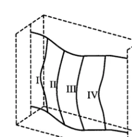
For instruments mounted on an internal frame, one can use two different approaches. In one of the two, it can be assumed that the complete frame vibrates as a rectangular panel and the same Ritz vectors can be used to represent the displacement shapes in all the parallel (vertical or horizontal) frame members (Gupta et al. 1999). This approach would be suitable for a frame shown in Fig. 2. For a frame in which members are connected only at its ends, as shown in Fig. 3, parallel frame members can vibrate in different displacement shapes due to differences in boundary conditions and non- uniform mass distribution. In such cases, different Ritz vectors can be used for different but parallel frame members (Gupta and Yang 2001).
~lv
L o c a l / # members
Local members
Olh
Fig. 2 Internal Frame, Parallel Members Vibrate in Same Shape
~ V
I I ".~...~..
I ! II ~ s S I
! II ! I
: ~ Y
I - T - - - T - ~ ,
:
! i ,~ I I I I I
I I II I I I I i
! I T I I I I I I !
I k I .LXLJ T ~ Z | I I
! i il I I • v t i I
I i I| l | ~ i i
" ~ ~ . . . 2 1 2 . . ~ J '
R O C K I N G STIFFNESS OF M O U N T I N G A R R A N G E M E N T
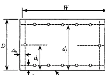
As stated earlier, a rigid-body rocking mode exists in cabinets that are anchored to the floor. Consideration of the rocking cabinet mode in the Ritz-vector approach requires knowledge of the rocking stiffness imparted by the mounting arrangement at the cabinet base. If the rocking stiffness for a particular mounting arrangement is known a-priori, it can be input into INCABS directly. INCABS can also be used to calculate the rocking stiffness for three different types of mounting configurations. Simple formulations developed by Yang et al. (2001) are used for this purpose. The three configurations are shown in Figs. 4-6. Configurations 1 and 2 consist of anchor bolts and a base plate with the primary difference that configuration 2 contains anchor bolts only at the four corners of the base plate whereas there are no anchor bolts at the corners in configuration 1. Configuration 3 may consist of m bays in which triangular base plates are used for anchoring. The outer frame consists of channel sections and the bays are separated by tubular beams. It should be noted that for a cabinet in which the configuration of mounting arrangement is significantly different from these three configurations, the rocking stiffness has to be determined a-priori for input into INCABS else this program cannot be used for evaluating the cabinet dynamic properties. The rocking stiffness for mounting configurations 1 and 2 are given by
K°
= - O = \ / / = 1 12(1- V 2 ) A~where, E and v are Young's modulus and Poisson's ratio for the base plate material, respectively. The plate thickness is t and all the other parameters are described in Figs. 4-6. A detailed parametric study was conducted to evaluate the value of constant C. Its value was found to be 6.71 for configuration 1 and 13.30 for configuration 2. For configuration 3 consisting of m bays, the rocking stiffness is given by
I
/
K o =2K v~_~d 2+(m-1 2Kv D2+ L3
(3)i=1
where I is the moment of inertia for the tubular beam. The value of C evaluated from the parametric study for this configuration was found to be 16.44.
.,[ W >i
- . - - . - - - . - - - . . - - . - - - . - - , -
I I
! !
° l
-,
'~Ab ~ ' - - Front edge
Fig. 4 Mounting Configuration 1
D
- d r - -
" "- Front edge
Fig. 5 Mounting Configuration 2
Channels Tubular beams
J
~¢A b ~D
t A b I
A P P L I C A T I O N S
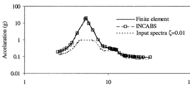
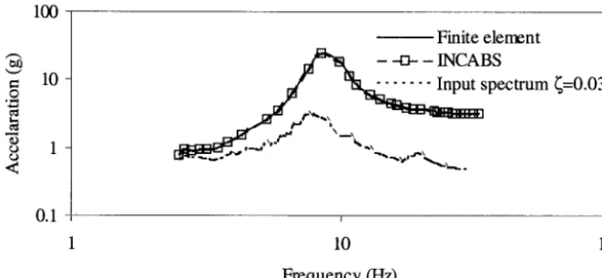
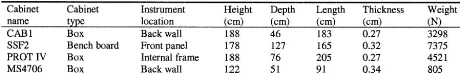
Computer program INCABS has been applied to several actual cabinets. Figs. 7-9 compares the incabinet spectra evaluated using INCABS with the corresponding spectra obtained from detailed finite element analyses of three different types of cabinets, shown in Figs. 10-12 and whose characteristics are described in Table 1. The significant mode in cabinet CAB 1 for instruments located on the back wall is a local back wall mode. The global rocking or bending mode of this bench board does not contribute significantly in the non-rigid frequency region. The same is also true for the cabinet PROT IV in which instruments are mounted on a frame of the type shown in Fig. 3. The significant mode for a particular instrument location is the local mode of the frame that is calculated by using different Ritz vectors for different vertical members. The instruments in bench board SSF2 are mounted on the front panel that is inclined to the global axes. No side walls exist in this cabinet. Therefore, the significant mode is a superposition of the local mode of the front panel and the global bending mode of the cabinet. The significant mode in cabinet MS4706, Fig. 13, for instruments located on the back wall is a superposition of the local back wall mode and the global rocking mode. The mounting configuration in this cabinet is same as configuration 2 shown in Fig. 5. The rocking stiffness of the mounting arrangement in this cabinet as calculated from a finite element analysis is found to be 0.40x10⁸ kg-cm/rad. The corresponding value obtained from Eq. 2 is 0.41x10⁸ kg-crn/rad. In addition to electrical cabinets and control panels, INCABS has also been used for static and dynamic analysis of building slabs supported on edge beams (Yang and Gupta, 2001). A web based application of INCABS can be electronically integrated with the procurement process for reducing the engineering costs whereas elimination of excessive conservatism is likely to enable the use of commercial grade instruments leading to a reduction in hardware costs. A method to account for uncertainties as well as evaluate incabinet spectra consistent with specified reliability levels is being developed for incorporation in INCABS.
100
~" 10
< 0.1
0.01
A Finite element
- -43- - INCABS
. . . pectra ~=0.01
I
10
Frequency (Hz)
Fig. 7 Incabinet Response Spectra, CAB1 (1% damping)
100
100-
~o
= 10-
Q
0.1
Finite element - --0- - INCABS 2511 I . . ~
~ s p e c t r u m ~=0.03
I
10
Frequency (Hz)
Fig. 8 Incabinet Response Spectra, SSF2 (3% damping)
O
0v,=W
~D ¢D ¢D
< 100
10-
1 -
0.I
--- Finite element
~
- -o- - INCABS~ r ~ , ~ s p e c t r u m ~=0.03
-,~ aa~ap~,~o_~O,o.O._ l ~ . ,
. ,~.,,,,.. ~ " ~ " ~ ,~,,~ " ~ , , , ~
1 10 100
Frequency (I-Iz)
Fig. 9 Incabinet R e s p o n s e Spectra, P R O T IV ( 3 % d a m p i n g , m e m b e r I)
46cm ~ ~ 183cm
¢
-
Back
188cm ~.A ~wall 188cm
¢ A
~ 2
Fr, . . .
- 41cm41cm
76cm ~ ~ ' / r . ~ 4 1 c ~ ,._~
/ ,," I - ~'"-~.. ~I"~'".]I~,~_H" 1 ~.' I t IA
I ! ! J l ~ . " , '
I I
I II
I
I~"~~r
i
I I
I II
I
I
I ~, ,~~
I ! ! i_l I I I i i ,~
I I i I I I
I I I lq .I
I
I
i ,
I ! ! i l XXl rrd I i i I
I ! ! i I I IHI -,-.,,i i i I
i .~ ~ i l I I IVI i i i
I I I I I
I E--LI_
I I I i i
1152cm
I, i 5 - ~ ' ~ z d _ - . _ l
I
I ' ,LI,-"
~ 1 . .
i l l
,4,_--- . . . . , ~ - . : - ~ ~
2 0 5 c m ~ , - . , ~ "~
Fig. 10 Box T y p e Cabinet, CAB1 Fig. 11 Internal F r a m e , C a b i n e t P R O T IV
64cm
91cm
51cm
85cm
~ ~ , X Z
165cm
127cm
178cm
50.8(
122cm
Table I Structural Properties and Configurations of Cabinets
Cabinet Cabinet Instrument Height Depth Length Thickness Weight
name type location (cm) (cm) (cm) (cm) (N)
CAB 1 Box Back wall 188 46 183 0.27 3298
SSF2 Bench board Front panel 178 127 165 0.32 7375
PROT IV Box Internal frame 188 76 205 0.27 4521
MS4706 Box Back wall 122 51 91 0.34 805
,
SUMMARY AND CONCLUSIONS
Computer program INCABS implements a new Ritz-vector approach developed by Gupta et al. (1999) and Gupta and Yang (2001) to calculate the dynamic properties of significant cabinet modes and the incabinet response spectra. INCABS takes only limited information on cabinet properties and evaluates realistic incabinet spectrum at an instrument location. It can account for the bending as well as the torsional stiffness of the constraining structural members such as stiffeners to account for the partial constraints imparted by them. INCABS uses simple formulations for evaluating the rocking stiffness for three different types of cabinet mounting arrangements. INCABS has been applied to several actual cabinets as well as building slabs with edge beams for evaluating the accuracy of calculated dynamic properties. It can be used both as a stand-alone program and as a web-based tool.
REFERENCES
1. Blevins, R., Formulas for Natural Frequency and Mode Shape, Van Nostrand Reinhold Company, New York, 1979. 2. Djordjevic, W., O'Sullivan, J. J., "Guidelines for Development of In-Cabinet Amplified Response Spectra for Electrical
Benchboards and Panels," Report. Stevenson & Associates, Inc. 1990.
3. Djordjevic, W., "Amplified Response Spectra for Devices in Electrical Cabinets," Proceedings of the 4th Symposium on Current Issues Related to Nuclear Power Plant Structures, Equipment and Piping,, December, Orlando, FL. 1992. 4. Gupta, A. and Gupta, A. K., "CREST-IRS, a Computer Program for Generating Instructure Response Spectra,"
Technical Report C-NPP-SEP 18/97, Dept. of Civil Engineering, North Carolina State University, Raleigh, NC, 1997. 5. Gupta, A., Rustogi, S. K. and Gupta, A. K., "Incabinet Response Spectra," Proceedings of the 7 th International
Symposium on Current Issues related to Nuclear Power Plant Structures, Equipment and Piping, pp. XI-I-I-XI-I-18, Raleigh, NC, December 1-4, 1998.
6. Gupta, A., Rustogi, S. K. and Gupta, A. K., "Ritz Vector Approach for Evaluation Incabinet Response Spectra", Nuclear Engineering and Design, Vol. 190, 1999, pp. 255-272.
7. Gupta, A. and Yang, J., "Modified Ritz Vector Approach for Dynamic Properties of Electrical Cabinets and Control Panels", Nuclear Engineering and Design, 2001, submitted.
8. Yang, J., Rustogi, S. K. and Gupta, A., "Rocking Stiffness of Mounting Arrangements in Electrical Cabinets and Control Panels", Nuclear Engineering and Design, 2001, submitted.
9. Yang, J. and Gupta, A., "Ritz Vector Approach for Static and Dynamic Analysis of Plates with Edge Beams", Journal of Sound and Vibration, 2001, submitted.
ACKNOWLEDGEMENT