Study of Effect of Shear Walls on Seismic
Behaviour of High Rise RCC Buildings by
Using ETABS
Ameer Qasim Suhail1, Dr. K. Sandeep Kumar2
Master of Tech.,(Structural Engineering), Department of Master of Technology (Structural Engineering), Acharya
Nagarjuna University, Guntur, Andhra Pradesh, India1
Assistant Professor , Department of Master of Technology (Structural Engineering), Acharya Nagarjuna University,
Guntur, Andhra Pradesh, India2
ABSTARCT: The practice before 1960s has been to design buildings primarily for gravity loads and check the adequacy of the structure for safety against lateral loads. It is established that the design of a multi-storey building is governed by lateral loads and it should be the prime concern of designer to provide adequate safety to structure against lateral loads. Many existing RC frame buildings located in seismic zones are deficient to withstand earthquakes. Insufficient lateral resistances and poor detailing of reinforcement are the main reasons for inadequate seismic performance. Shear wall system is one of the most generally used lateral-load resisting technique for high-rise buildings. Shear walls have very high in-plane strength and stiffness, which can be used simultaneously for resisting large horizontal and gravity loads. In tall buildings, it is very important to ensure adequate lateral stiffness to resist lateral load. The aim of this project is to determine the solution for shear wall location in multi-storey building. For this purpose four different models of four different storeyed building each has been considered i.e. one model without shear wall. Models are studied in high seismic zone for comparing lateral displacement and load transfer to various structural elements with different positioning of shear wall.(i.e the shear wall was placed at corner , corner and lift, alternative positions was compared with ordinary building(without shear walls)) Earthquake load is calculated as per IS: 1893-2002 (Part-1). Various parameters like response reduction factor, importance factor, zone factor etc. are taken from IS: 1893-2002 (Part-1) and are applied to a building located in Zone V. The buildings are modelled using software ETABS 9.7.4. Providing shear walls at adequate locations substantially reduce the displacements due to earthquake. Hence accounting shear wall in a building will form an efficient lateral force resisting system. It is concluded that small dimension of shear wall is not effective than large dimension of shear wall to control the lateral displacement in multi storied buildings.
KEYWORDS: Earthquake, vibration, shearwall, model,
I. INTRODUCTION
An earthquake (also known as a quake, tremor or temblor) is the perceptible shaking of the surface of the Earth, resulting from the sudden release of energy in the Earth's crust that creates seismic waves.Earthquakes can be violent enough to toss people around and destroy whole cities.Occurrences of recent earthquakes in India and in different parts
of the world
and the resulting losses, especially human lives, have highlighted the structural
inadequacy of buildings to carry seismic loads.
meaning earthquake and ‘logos’ meaning science. The study of seismic wave propagation through earth provides the maximum input to the understanding of internal structure of earth.
Vibrations in the tall structures are mainly due to either ground motions due to seismic or strong winds.In both conditions, the mechanism that influences the shaking characteristics of tall structures is the dynamic Soil-Structure Interaction (SSI), which is mainly influenced by the soil properties supporting the structure. In the conventional method of design of structures, generally the effects of soil supporting the structure are not considered. But past earthquake proved that if we neglect soil-structure interaction effect it will leads to severe damages and losses of lives especially when supporting soil is soft soil. The process in which the response of the soil influences the motion of the structure and motion of the structure influences the response of the soil is called as soil-structure interaction (SSI). In tall structures lateral loads are critical one, shear wall is one of the structural element which is very efficient in resisting lateral load. The importance of shear walls in the structural planning of multi-storey buildings plays an important role. When walls are situated in advantageous positions in a building, they can be very efficient in resisting lateral loads originating from wind or earthquakes.
There has been a considerable increase in the construction of tall buildings both residential and commercial and the modern trend is towards more tall and slender structures. Thus the effects of lateral loads like wind loads, earthquake loads and blast forces are attaining increasing importance and almost every designer is faced with the problems of providing adequate strength and stability against lateral loads. Shear wall system is one of the most commonly used lateral load resisting system in high rise buildings. Shear wall has high in plane stiffness and strength which can be used to simultaneously resist large horizontal loads and support gravity loads, which significantly reduces lateral sway of the building and thereby reduces damage to structure and its contents. Shear walls in buildings must be symmetrically located in plan to reduce ill-effects of twist in buildings. When shear walls are situated in advantageous positions in the building, they can form an efficient lateral force resisting system by reducing lateral displacements under earthquake loads. Therefore it is very necessary to determine effective, efficient and ideal location of shear wall.
Plate tectonics
The theory of plate tectonics, presented in early 1960s, explains that the lithosphere is broken into seven large (and several smaller) segments called plates.
This theory requires a source that can generate tremendous force is acting on the plates. The widely accepted explanation is based on the force offered by convection currents created by thermo-mechanical behavior of the earth’s subsurface. The variation of mantle density with temperature produces an unstable equilibrium. The colder and denser upper layer sinks under the action of gravity to the warmer bottom layer which is less dense. The lesser dense material rises upwards and the colder material as it sinks gets heated up and becomes less dense (refer Figure 1.4). These convection currents create shear stresses at the bottom of the plates which drags them along the surface of earth.
1.2 PERFORMANCE EVALUATION
Structural behaviour under seismic loading requires an understanding of the behaviour under large inelastic deformations. The capacity spectrum method is one of the most established and widely accepted displacement based seismic design method which is used for performance based seismic design.
The use of shear walls in the earthquake-resistant structural system of reinforced concrete buildings is not often in earthquake-prone countries. Nevertheless, the lessons learned from the seismic behavior of Chilean buildings during the March 3, 1985 earthquake, show that satisfactory seismic behavior may be achieved during severe earthquake events, when the total amount of wall cross sections is large enough, i.e., 0.02 to 0.03 times the floor plan area in each direction of seismic resistance for buildings up to 21-story high. In this event, both flexural yielding of boundary reinforcement and shear moments in walls were kept at a moderate level, nonstructural damage was adequately controlled due to the significant lateral stiffness of the structural system, and collapse of this type of buildings was practically prevented. The horizontal interaction moments between the soil and the foundation are arguably more problematic than the vertical moments, as comparatively little is known about allowable seismic passive pressures and the effect of seismic active pressure in different foundation situations. Indeed it is customary to assume even more arbitrary distributions for horizontal moment between foundations and soil than for vertical moment. The main problems of foundation design as presently understood occur in transferring the base shear of the structure to the ground, and in maintaining structural integrity of the foundation during differential soil deformations. According to The Council of Tall Buildings and Urban Habitat, the description of ‘Tall building’, equivalent to ‘High-rise building’ used herein, is: “A building whose height creates different conditions in the design, construction, and use than those that exist in common buildings of a certain region and period. A traditional height cutoff between high-rise and low-rise buildings is 35 meters or 12 floors. This distinction is used as 12-floors are generally considered to be the minimum height needed to achieve the physical presence to earn the recognition as a "high-rise". The twelve-floor limit is also seen as a compromise between ambition and manageability for use in classification of buildings in a worldwide database.
Performance-based design requires the designer to go beyond code prescriptions and accurately predict how a structure will respond to its environment, often during extreme events. To make these predictions often requires sophisticated structural analysis using state-of-the-art computer software, and sometimes requires laboratory testing. Also, determining the damage mechanisms and their thresholds (“fragility curves”) can benefit greatly from failure investigation experience. Because of the complexities involved, it is desirable (and often required) that an independent peer reviewer check a performance-based design. Peer reviewers with experience investigating failures can bring valuable insight to the designer who wishes to avoid seeing those failures repeated.
1.3 STRUCTURAL TYPES
The significant innovation in high-rises was proposed by Khan and Rankine (1980), who proposed the idea of using a hollow thin-walled tube with punched holes to form the exterior of buildings. By reducing the spacing of exterior columns, the entire system of beams and columns lying on the external perimeter of a building can be made to act as a perforated or framed tube. The analysis methods Ali (2001) for RC high-rise buildings have special requirements different from low-to-middle rise buildings, especially for the typical structural system that consists of slender members in frames and more RC stocky structural walls. The complexities of concrete properties, wall-frame interaction and three-dimensional effects need to be accounted for in structural modeling.
which account for the inelastic behavior, generally use the results of static collapse analysis to define the global inelastic performance of the structure. Seismic demands are computed by nonlinear static analysis of the structure subjected to monotonically increasing lateral forces with an invariant height-wise distribution until a predetermined target displacement is reached.non linear dynamic methods are becoming practical tools of analysis and evaluation of buildings considering the performance-based seismic philosophy. This is evident by the recent implementation ofnon linear dynamic methods in several international seismic guidelines and codes, such as the Federal Emergency Management Agency standard 273 (FEMA- 273), Euro-Code 8 (EC-8) and International Building Code (IBC-2003). In these seismic regulations, non linear dynamic methods of analysis such as the N2-method and the capacity spectrum method are recommended for determining the inelastic responses of the building due to earthquake ground motions. One main step in thesenon linear dynamic methods of analysis for determining the seismic demands is the construction of thenon linear dynamic curve of the building by using an adequate lateral load pattern simulating the distribution of inertia forces developed through the building when subjected to an earthquake. Thisnon linear dynamic curve represents the lateral capacity of the building by plotting the nonlinear relation between the base shear and roof displacement of the building. The intersection of thisnon linear dynamic curve with the seismic demand curve determined by the design response spectrum represents the deformation state at which the performance of the building is evaluated. Structures designed according to the existing seismic codes provide minimum safety to preserve life and in a major earthquake, they assure at least gravity load bearing elements of non-essential facilities will still function and provide some margin of safety.
However, compliance with the standard does not guarantee such performance. They typically do not address performance of non-structural components neither provide differences in performance between different structural systems. This is because it cannot accurately estimate the inelastic strength and deformation of each member due to linear elastic analysis. Although an elastic analysis gives a good indication of the elastic capacity of structures and indicates where first yielding will occur, it cannot predict failure mechanisms and account for redistribution of forces during progressive yielding. Inelastic analyses procedures help demonstrate how buildings really work by identifying modes of failure and the potential for progressive collapse. The use of inelastic procedures for design and evaluation is an attempt to help engineers better understands how structures will behave when subjected to major earthquakes, where it is assumed that the elastic capacity of the structure will be exceeded..
Shear walls are the structural system used to increase the strength of R.C.C Structure. In high rise buildings the shear wall are used to resist lateral loads that may be caused by wind and seismic motion. R.C. Shear wall provide large strength and stiffness to the building in the direction of their orientation which considerably reduces lateral sway of the building and there by reduces damage to the structure. If a high rise R.C. Structure is designed without shear wall the beam and column sizes are large and so many problems arises at the joints and due to this it is difficult to place and vibrate the concrete at such places and displacement is more which in turn induces heavy forces on the structure therefore shear wall become essential from the point of view of economy.
By providing shear wall the structure become safe and durable and also more stable the function of shear wall is to increase rigidity for wind and seismic load resistance. The use of shear wall gains more popularity in the construction of service apartments or office. In this paper the main aim is to study the optimum location and its effectiveness of shear wall in regular high rise R.C Building. In this paper we also considered regular R.C. Building with twenty onestorey’s and have been modeled using software package ETABS for earth quake Zone-5.and wind load The effect of shear wall has been studied in this paper with the help of three different models.
Model 1 is bare frame structural system and other two models are dual type structural system. The comparison of these models with different parameters like Storey displacement, Storey drift, and Storey shear has been presented by replacing the column with shear wall.
This study presents the procedure for seismic performance estimation of high-rise buildings based on a concept of the capacity spectrum method. In 3D analytical model of twenty one storied buildings have been generated for symmetric buildings Models and analyzed using structural analysis tool ETABS. The analytical model of the building includes all important components that influence the mass, strength, stiffness and deformability of the structure. To study the effect of concrete core wall & shear wall at different positions during earthquake, seismic analysis using nonlinear dynamic procedure has been performed.
The deflections at each storey level has been compared by performing asnon linear dynamic method has also been performed to determine capacity, demand and performance level of the considered building models. From the below studies it has been observed that non linear dynamic analysis provide good estimate of global as well as local inelastic deformation demands and also reveals design weakness that may remain hidden in an elastic analysis and also the performance level of the structure. Storey drifts are found within the limit as specified by code (IS: 1893-2002) in non linear dynamic analysis.
Now a days we are seeing a rapidly increasing the cost of land not only in India even all over the world and also we need to preserve our important agricultural productive land too. All contributed towards both residential and commercial structures growth in vertical direction that is high rise structure. Behaviour of these high rise structures especially with regular configuration during hazards like earthquake, wind are nowadays prime topic of study of structural engineering.
1.4 SHEAR WALL
Shear walls are vertical elements of the horizontal force resisting system. Shear walls are constructed to counter the effects of lateral load acting on a structure. In residential construction, shear walls are straight external walls that typically form a box which provides all of the lateral support for the building. When shear walls are designed and constructed properly, and they will have the strength and stiffness to resist the horizontal forces.
In building construction, a rigid vertical diaphragm capable of transferring lateral forces from exterior walls, floors, and roofs to the ground foundation in a direction parallel to their planes. Examples are the reinforced-concrete wall or vertical truss. Lateral forces caused by wind, earthquake, and uneven settlement loads, in addition to the weight of structure and occupants; create powerful twisting (torsion) forces. These forces can literally tear (shear) a building apart. Reinforcing a frame by attaching or placing a rigid wall inside it maintains the shape of the frame and prevents rotation at the joints. Shear walls are especially important in high-rise buildings subjected to lateral wind and seismic forces.
In the last two decades, shear walls became an important part of mid and high-rise residential buildings. As part of an earthquake resistant building design, these walls are placed in building plans reducing lateral displacements under earthquake loads. So shear-wall frame structures are obtained.
Shear wall buildings are usually regular in plan and in elevation. However, in some buildings, lower floors are used for commercial purposes and the buildings are characterized with larger plan dimensions at those floors. In other cases, there are setbacks at higher floor levels. Shear wall buildings are commonly used for residential purposes and can house from 100 to 500 inhabitants per building.
hear wall is a structural member used to resist lateral forces i.e. parallel to the plane of the wall. For slender walls where the bending deformation is more, Shear wall resists the loads due to Cantilever Action. In other words, Shear walls are vertical elements of the horizontal force resisting system.
In building construction, a rigid vertical diaphragm capable of transferring lateral forces from exterior walls, floors, and roofs to the ground foundation in a direction parallel to their planes. Examples are the reinforced-concrete wall. Lateral forces caused by wind, earthquake, and uneven settlement loads, in addition to the weight of structure and occupants, create powerful twisting (torsional) forces. This leads to the failure of the structures by shear.
Shear walls are especially important in high-rise buildings subject to lateral wind and seismic forces. Generally, shear walls are either plane or flanged in section, while core walls consist of channel sections. They also provide adequate strength and stiffness to control lateral displacements.
best position for the shear walls is in the center of each half of the building. This is rarely practical, since it also utilizes the space a lot, so they are positioned at the ends. It is better to use walls with no openings in them. So, usually, the walls around lift shafts and stairwells are used. Also, walls on the sides of buildings that have no windows can be used.
1.5 PURPOSE OF CONSTRCTING SHEAR WALLS
Shear walls are not only designed to resist gravity / vertical loads (due to its self-weight and other living / moving loads), but they are also designed for lateral loads of earthquakes / wind. The walls are structurally integrated with roofs / floors (diaphragms) and other lateral walls running across at right angles, thereby giving the three dimensional stability for the building structures.
Shear wall structural systems are more stable. Because, their supporting area (total cross-sectional area of all shear walls) with reference to total plans area of building, is comparatively more, unlike in the case of RCC framed structures.
Walls have to resist the uplift forces caused by the pull of the wind. Walls have to resist the shear forces that try to push the walls over. Walls have to resist the lateral force of the wind that tries to push the walls in and pull them away from the building.
Shear walls are quick in construction, as the method adopted to construct is concreting the members using formwork.
Shear walls doesn’t need any extra plastering or finishing as the wall itself gives such a high level of precision, that it doesn’t require plastering.
II. DESIGN OF SHEAR WALL 2.1 GENERAL
Overall dimensions up to the 21th storey, the column cross section is taken as 0.50 x 0.50meters and the beam dimensions are 0.45 x 0.45 meters. The floor slabs are modeled as membrane element of 0.15m thickness. All the supports are modeled as fixed supports. Non Linear dynamic analysis is conducted on these models. The loads are considered for the analysis is given below.
Imposed Load:- The imposed load on the floor is obtained from Table 1 of IS 875 (Part 2) – 1987. The uniformly distributed load on the floor of the building is assumed to be 3 kN/m2 (for assembly areas, corridors, passages, restaurants, business and office buildings, retail shops etc).
Earth Quake Load:- The structure is assumed to be in Hyderabad (Zone 5 as per IS 1893 – 2002). So the zone factor is taken as 0.36 as per Table 2 of IS 1893 – 2002. The damping is assumed to be 5%, for concrete as per Table 3 of IS 1893 –2002. Importance factor is taken as 1.5 as per Table 6 of IS 1893 – 2002.
Wind load : According to the provisions of Bureau of Indian Standards for wind loads, IS 875 (Part 3):1987 dynamic analysis for wind load is suggested for closed buildings with height to minimum lateral dimension ratio of more than 5 or fundamental frequency of the building less than 1 Hz.
2.2 LATERAL LOAD EFFECTS
Any structure subjected to seismic force during an earthquake, the seismic waves that arrive produces motions in the structure itself. Motions depend on the structures vibration characteristics and the structural layout or building. For the structure to response to the motion, it needs to overcome its own inertia, which results in an interaction between the structure and the soil. Such an interdependent behavior between soil and structure regulating the overall response is referred as interaction behavior in the present context. Basically the dynamic soil-structure interaction consists of two interactions, kinematic interaction and inertial interaction.
Kinematic interaction is characterized as motion of the structure due to rigid body displacement of the ground surface. The assumption made by the kinematic interaction is assumes that the building foundation has no mass, structure has no mass and foundation of the building is completely rigid.
Inertial interaction is characterized by the motion and deformation of the foundation and structure apart from the motion of the surrounding soil. Assume that the building’s foundation is completely flexible and that the building has been completely separated from the ground. During an earthquake, the ground motion is transmitted from the soil into the building.
2.3 ROLE OF SHEAR WALL
Generally shear walls are the structural vertical member mainly provided to resist lateral load due wind or earthquake. Reinforced concrete shear walls provide high in plane stiffness and strength to the buildings in the direction of their orientation of shear walls, which is considerably reduces the lateral sway of the buildings and thereby controls damage of the structure and its elements. Since shear walls mainly carries large horizontal load due to earthquake or wind forces, the overturning effects are more in the structure sometimes. Theses shear wall also resist part of gravity load along with the lateral load. The arrangement of shear wall in the plan is important to achieve the required stiffness and reduce effects of twist in buildings for the system.
2.4 COMPARISONS OF SHEAR WALL WITH CONSTRUCTION OF CONVENTIONAL LOAD BEARING WALLS
wall concept of box like three-dimensional structures. Though it is possible to design the earthquake resistant RCC frame, it requires extraordinary skills at design, detailing and construction levels, which cannot be anticipated in all types of construction projects. On the other hand even moderately designed shear wall structures not only more stable, but also comparatively quite ductile. In safety terms it means that, during very severe earthquakes they will not suddenly collapse causing death of people. They give enough indicative warnings such as widening structural cracks, yielding rods, etc., offering most precious moments for people to run out off structures, before they totally collapse.
For structural purposes we consider the exterior walls as the shear-resisting walls. Forces from the ceiling and roof diaphragms make their way to the outside along assumed paths, enter the walls, and exit at the foundation.
2.5 FORCES ON SHEAR WALL
Shear walls resist two types of forces: shear forces and uplift forces. Shear forces are generated in stationary buildings by accelerations resulting from ground movement and by external forces like wind and waves. This action creates shear forces throughout the height of the wall between the top and bottom shear wall connections.
Uplift forces exist on shear walls because the horizontal forces are applied to the top of the wall. These uplift forces try to lift up one end of the wall and push the other end down. In some cases, the uplift force is large enough to tip the wall over. Uplift forces are greater on tall short walls and less on low long walls. Bearing walls have less uplift than non-bearing walls because gravity loads on shear walls help them resist uplift. Shear walls need hold down devices at each end when the gravity loads cannot resist all of the uplift. The hold down device then provides the necessary uplift resistance.
Shear walls should be located on each level of the structure including the crawl space. To form an effective box structure, equal length shear walls should be placed symmetrically on all four exterior walls of the building. Shear walls should be added to the building interior when the exterior walls cannot provide sufficient strength and stiffness.
Shear walls are most efficient when they are aligned vertically and are supported on foundation walls or footings. When exterior shear walls do not provide sufficient strength, other parts of the building will need additional strengthening. Consider the common case of an interior wall supported by a sub floor over a crawl space and there is no continuous footing beneath the wall. For this wall to be used as shear wall, the sub floor and its connections will have to be strengthened near the wall.
For Retrofit work, existing floor construction is not easily changed. That’s the reason why most retrofit work uses walls with continuous footings underneath them as shear walls.
2.6 CLASSIFICATION OF SHEAR WALLS
Simple rectangular types and flanged walls (bar bell type) Coupled shear walls
Rigid frame shear walls
Framed walls with in filled frames Column supported shear walls Core type shear walls
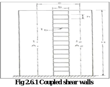
2.6.1 Coupled Shear Walls
Structural wall systems are like vertically-oriented wide beams, behaves as a slender cantilever beam under lateral loads.Coupling beams are expected to suffer large inelastic load reversals during strong earthquakes as they act as primary system for energy dissipation. Strength of coupling beams should not be so great that the wall system behaves as a single cantilever structural element. The design should be with the weak beam and strong wall concept. They should be designed to withstand large imposed deformations and with high energy dissipation capacity. The shear-span to effective-depth ratio is an important parameter affecting the behaviour of coupling beam.
C-shaped (50%), Lshaped (30%), planar (10%), and other (10%) wall components. In planar coupled shear wall analyses, the lateral loads
are applied in such a way that the deformation of the shear wall is confined within its own plane. A thorough shear wall analysis requires considering in-plane, out-of- plane and torsional deformations. In non-planar coupled shear walls, both the flexural and torsional behaviours under external loading have to be taken into account in the analysis.
Fig 2.6.1 Coupled shear walls 2.6.2 Rigid Frame Shear Walls
In multistory building with shear walls, the lateral loads due to wind or seismic action are resisted by a combination of shear walls and rigid frames. The rigid frames consist of all columns and the connecting beams and slabs. If a few simple assumptions are made with regard to the properties of the building, it is possible to express the angle deflection of the wall at all points with a second degree differential equation, taking Into account the effect of bending and shear. First, the assumption is made that the shear walls are fixed at their bases; but it is later shown how elastic sup- ports or hinged bases can be considered.
2.6.3Framed Walls With In Filled Frames
When the tall building has both shear wall and frame to resist lateral load and shear wall deflect in bending mode under horizontal load and frame under horizontal load deflect in shear mode. Due to the infinity rigidity of the floor diaphragm, the main function of this structure increases the rigidity for lateral load resistance. Shear wall and frames have the same deflection each floor level, modifies the final behavior of these element know as shear wall-frame interaction
2.6.4 Column Supported Shear Walls
2.6.5 Core Type Shear Walls
A shear wall is a structural panel that can resist lateral forces acting on it. Shear walls can be positioned at the
perimeter of buildings or they may form a shear core – a structure of shear walls in the centre of a building, typically
encasing a lift shaft or stairwell.
III. TERRIAN CATEGORY TERRIAN CATEGORY 1
IV. RESULTS AND ANALYSIS 5.1 STORY DRIFT IN X DIRECTION
0 50000 100000 150000 200000 250000 300000 350000 400000
BENDING MOMENT IN X DIRECTION
BENDING MOMENT IN X DIRECTION (MX) IN GENERAL BUILDING
V. CONCLUSIONS
From the present investigation and the results obtained it can be concluded as following:
1) In high rise buildings (ie greater than 10 storeys) provision of shear walls is found to be effective in enhancing the overall seismic capacity characteristics of the structure.
2) From the comparison of story drift values it can be observed that maximum reduction in drift values is obtained when shear walls are provided at both corners and lift of the building.
3) From the story shear results it was observed that the shear wall at corner and lift is provided is the best , comparison of the three model types
4) From the support reactions results it was observed that the shear wall at corner and lift is provided is the best, when compared to the other two type of model structure
5) the optimum placement of shear walls can be find by placing the shear walls at different places and founded that the shear wall at corner and lift is best suited for high rise structures.
VI. SCOPE FOR FUTURE RESEARCH
The volume of work undertaken in this study is limited to comparison of seismic response parameters in a building with different shear wall locations using non linear analyses .The study could be extended by including various other parameters such as torsional effects and soft storey effects in a building .linear dynamic analysis, push over analysis may be carried out for further study for better and realistic evaluation of structural response under seismic forces
REFERENCES
1. HimaleeRahangdale ,S.R.Satone, Design And Analysis Of Multi storied Building With Effect Of Shear Wall, Vol. 3, Issue 3, May-Jun 2013, pp.223- 232.
2. M.Y. Kaltakci, M.H. Arslan and G. Yavuz, Effect of Internal and External Shear Wall Location on Strengthening Weak RC Frames, Sharif University of Technology, August 2010,Vol. 17, No. 4, pp. 312- 323.
3. Shaik Kamal Mohammed Azam, VinodHosur, Seismic Performance Evaluation of Multistoried RC framed buildings with Shear wall, International Journal of Scientific & Engineering Research Volume 4, Issue 1, January-2013
4. P. B. Oni, Dr. S. B.Vanakudre, Performance Based Evaluation of Shear Walled RCC Building bynon linear dynamic Analysis, International Journal of Modern Engineering Research (IJMER) , Vol. 3, Issue. 4, Jul - Aug. 2013 pp-2522-2525.
5. D. B. Karwar, Dr. R. S. Londhe, Performance of RC framed structure usingnon linear dynamic analysis ,International Journal of Emerging Technology and Advanced Engineering, Volume 4, Issue 6, June 2014
0 100000 200000 300000 400000 ST O R Y 2 1 ST O R Y 1 9 ST O R Y 1 7 ST O R Y 1 5 ST O R Y 1 3 ST O R Y 1 1 ST O R Y 9 ST O R Y 7 ST O R Y 5 ST O R Y 3 ST O R Y 1
BENDING MOMENT IN Y
DIRECTION
BENDING MOMENT IN Y DIRECTION (MY) IN GENERAL BUILDING
6. Yousuf Dinar, Md. Imam Hossain, Rajib Kumar Biswas, Md. MasudRana, Descriptive study ofnon linear dynamic analysis in RC structures of Rigid joint, IOSR Journal of Mechanical and Civil Engineering (IOSR-JMCE), Volume 11, Issue 1 Ver. II (Jan. 2014), PP 60-68
7. ATC-40. “Seismic evaluation and retrofit of concrete buildings.”Volume 1 and 2.Applied Technology Council, California, 1996. [5] FEMA-273. “NEHRP guidelines for the seismic rehabilitation of buildings.”Federal Emergency Management Agency, Washington DC, 1997.
8. FEMA-356. “Prestandard and commentary for the seismic rehabilitation of buildings.”Federal Emergency Management Agency, Washington DC, 2000.
9. IS: 1893 (Part 1) 2002- Indian standard- “Criteria for earthquake resistant design of structures”, Bureau of Indian Standards, New Delhi. 10. U.H. Varnayi in his second edition of “Design of structures”
11.S.K. Duggal in his “ Earth quake resistant design of structures” Page no:301 ,8.12 about Shear walls.
12. S.K. Duggal in his “ Earth quake resistant design of structures “ pg.no:305 on flexural strength 8.14.1 case:1, case:2.
13.S.K. Duggal in his “ Earth quake resistant design of structures” 8.16 Design of Shear walls which is also given in Is code 13920:1993
14.Mr A.P. Jadhav Associate Professor Rajarambapu Institute of technology rajaramnagar, Islampur has given a detailed report on the form work used for the construction of shear walls.
15.A report on effects of openings in shear walls on seismic response of structure by sharminrizachowdhary, department of civil engineering dhake-1208, Bangladesh mostly focused on the design of shear walls with openings on seismic response using E- Tabs
16. I.S 456:2000 As per clause 32, design for wall describes, design of horizontal shear in clause 32.4 given details of how shear wall have to be constructed.
17. I.S:1893 Criteria of Earth Quake resistant Buildings Part (3) page 23, clause 4.2 gives the estimation of earth quake loads.