Volume 3, No. 1, Jan-Feb 2012
International Journal of Advanced Research in Computer Science
RESEARCH PAPER
Available Online at www.ijarcs.info
ISSN No. 0976-5697
Development of Automated Teller Machine System Using JAVA
Surajit Borah*
B. Tech-Computer Science and Engineering Department of Computer Science and Engineering
Shillong Engineering and Management College Meghalaya, India-793101
Shinjit Kamal Borah
B. Tech-Computer Science and Engineering Department of Computer Science and Engineering
Shillong Engineering and Management College Meghalaya, India-793101
Abstract: To deposit or withdrawal amount from the banks manually is a time consuming process. To make this manual process fast this proposed system Automated Teller Machine (ATM) System has been designed. This proposed system deals with all transactions of actual AT M centers like login to customer account according to his pin number given, checking balance amount of savings account as well as current account. Also the account holder can deposit or withdraw amount from his current account or savings account respectively from any location. There will be no need of any human power to maintain the accounts. Since the all mathematical operation are done using program so it is error free and fast. The source independent java programming language is used to develop the system. Microsoft Access is used for storing all data or recor ds. Induction method is used for system testing.
Keywords: ATM, Microsoft access, source independent JAVA, fast data processing, security.
I. INTRODUCTION
An Automated Teller Machine System is a safety-critical and real-time system that is highly complicated in design and implementation. It is a computerized telecommunications device that provides the clients of a financial institution with access to financial transactions in a public space without the need for a cashier, human clerk or bank teller. On most modern ATMs, the customer is identified by inserting a plastic ATM card with a magnetic stripe or a plastic smart card with a chip that contains a unique card number and some security information such as an expiration date or CVVC (CVV).
Authentication is provided by the customer entering a personal identification number (PIN). This project is designed in such a way that the user has to enter pin number. Once verified, he/she is provided a menu and he/she has to enter the option provided in the menu. For example, when the user wants to withdraw cash, he/she has to enter the option for withdraw and from which account he/she wants to withdraw. After the option is entered along with the respective argument, if the transaction is possible the amount will be deducted from account and a message will be displayed on the screen. If the transaction is not possible an error message will be displayed on the screen.
II. PROJECT MANAGEMENT
Our goal is to establish a pragmatic strategy for controlling, tracking, and monitoring a complex technical project.
In project management following things must be done. a. Project Planning and Scheduling
b. Risk Management c. Estimation
In Project planning and scheduling, Planning of the project is done. In scheduling different task are schedule according to the deadline of the project.
A. Project Planning and Scheduling:
Project planning must deals with the following things. a) Project Complexity: - Project complexity has a strong
effect but is heavily influenced by past practitioner experience.
b) Project Size: - As size increases the interdependency of elements also grow.
c) The Degree of Structural Uncertainty: - the degree to which requirements are solidified and the ease of functional decomposition. The purpose of project planning is to ensure that the end result is completed on time, within budget, and exhibits quality.
[image:1.612.324.583.443.653.2]B. Project Development Approach:
Figure 1: Spiral model of software development
incremental versions of the software. Using the spiral model, software is developed in series of incremental release.
A spiral model is divided into a number of framework activities, also called task regions. There are between three and six task regions. Figure depicts a spiral model that contains six task regions:
a) Customer communication – tasks required to establish
effective communication between developer and customer.
b) Planning – tasks required to define resources,
timelines, and other project related information. c) Risk analysis – tasks required to assess both technical
and management risks.
d) Engineering – tasks required to build one or more representations of the application.
e) Construction and release – tasks required to construct,
test, install, and provide user support.
f) Customer evolution – tasks required to obtain customer
feedback based on evolution of the software representations created during the engineering stage and implemented during the installation stage.
Each of the regions is populated by a set of work tasks, called a task set, that are adapted to the characteristics of the project to be undertaken. For small projects, the number of work tasks and their formality is low. For larger, more critical projects, each task region contains more work tasks that are defined to achieve a higher level of formality [1].
In our case, we have to provide medium level of formality for making a good project report. We will take decision about cost, schedule and number of iterations required to complete the software.
III. ADVANTAGES OF PROPOSED SYSTEM
a. Very fast and accurate.
b. No need of any extra manual effort. c. No fever of data loss.
d. Just need a little knowledge to operate the system.
IV. FEASIBILITY STUDY
Once the problem is clearly understood, the next step is to conduct feasibility study, which is high-level capsule version of the entered systems and design process [2]. The objective is to determine whether or not the proposed system is feasible. The tests of feasibility have been carried out.
a. Technical b. Feasibility
c. Economical Feasibility d. Operational Feasibility
A. Technical Feasibility:
In Technical Feasibility study, one has to test whether the proposed system can be developed using existing technology or not. It is planned to implement the proposed system using java technology. It is evident that the necessary hardware and software are available for development and implementation of the proposed system. Hence, the solution is technically feasible.
B. Economic Feasibility:
As part of this, the costs and benefits associated with the proposed system compared and the project is economically feasible only if tangible or intangible benefits outweigh costs. The system development costs will be significant. So the proposed system is economically feasible.
C. Operational Feasibility:
It is a standard that ensures interoperability without stifling competition and innovation among users, to the benefit of the public both in terms of cost and service quality [3]. The proposed system is acceptable to users. So the proposed system is operationally feasible.
V. DATA MODELING
A. Data Dictionary:
A special set of tables called the data dictionary or data directory. A data dictionary contains metadata—that is, data about data. The schema of a table is an example of metadata. A database system consults the data dictionary before reading or modifying actual data [3]. The data values stored in the database must satisfy certain consistency constraints.
B. Importance of Data Dictionary:
Analysis use data dictionary for five important reasons: a. To manage the detail in large system.
b. To communicate a common meaning for all system elements.
c. To Document the feature of the system.
d. To Facilitates analysis of the details in order to evaluate characteristics and determine where system changes should be made.
e. To locate error and omissions in the system.
VI. DATA FLOW DIAGRAM
Data Flow Diagrams are the central tool and the basis from which other components are developed. The transformation of data from input to output, processes, may be described logically and independently of the physical components associated with the system. The DFD is also known as a data flow graph or a bubble chart. A graphical tool used to describe and analyze the moment of data through a system manual or automated including the process, stores of data, and delays in the system. Data Flow Diagrams are the central tool and the basis from which other components are developed [4]. The transformation of data from input to output, through processes, may be described logically and independently of the physical components associated with the system. The DFD is also known as a data flow graph or a bubble chart.
A. Physical DFD:
Structured analysis states that the current system should be first understand correctly. The physical DFD is the model of the current system and is used to ensure that the current system has been clearly understood. Physical DFDs shows actual devices, departments, and people etc., involved in the current system.
B. Logical DFD:
Logical DFDs are the model of the proposed system. They clearly should show the requirements on which the new system should be built. Later during design activity this is taken as the basis for drawing the system’s structure charts.
C. Context Diagram (0 Level DFD):
[image:3.612.336.564.85.298.2]The top-level diagram is often called a ―context diagram”. It contains a single process, but it plays a very important role in studying the current system. The context diagram defines the system that will be studied in the sense that it determines the boundaries. Anything that is not inside the process identifies the context diagram will not be part of the system study.
Figure 2: 0 level DFD
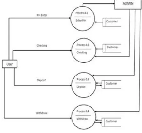
D. Data Flow Diagram (Level-1):
In Automated Teller System project, there are four processes like Pin enter, Checking, Deposit and Withdraw. Database of the project is customer. User enter the pin admin (Administrator) will verify the pin with the help of customer database. If pin is correct, admin allows the user to process the other processes like checking, deposit. Checking process reads
[image:3.612.328.572.450.636.2]the data from database, similarly deposit and withdraws reads as well as writes data in database.
Figure 3: Data flow diagram (Level 1)
VII. E-R DIAGRAM
An entity-relationship (ER) diagram is a specialized graphic that illustrates the relationships between entities in a database. ER diagrams often use symbols to represent three different types of information [6]. Boxes are commonly used to entities. Diamonds are normally used to represent relationships and ovals are used to represent attributes.
The E-R Diagram for the proposed system is as shown below:
Figure 4: ER diagram
[image:3.612.41.285.503.624.2]number, Account balances. Customer and Saving Account have two relations one to one withdraw and one to one deposit relation. Customer and Current Account also have two relations one to one withdraw and one to one deposit relation.
VIII. STATE FLOW DIAGRAM
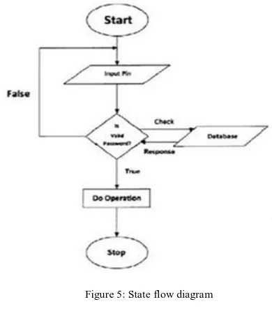
[image:4.612.327.575.201.275.2]State Flow Diagram shows how control follows in the software. In this project, after the application start user enters the pin and system verifies the PIN. If the process satisfies true condition (i.e. PIN match) user can go for further process and finally system stops after completing all required operations. Else system goes to initial state as shown below state flow diagram [7].
Figure 5: State flow diagram
IX. STRUCTURE DIAGRAM
[image:4.612.55.250.221.444.2]Structure diagrams emphasize the things that must be present in the system being modeled. Since structure diagrams represent the structure, they are used extensively in documenting the software architecture of software systems.
Figure 6: Structure diagram
X. DATABASE STRUCTURE (TABLES):
Table Name: Customer
Purpose: Store the details information of customer
Table Name: Current Account
Purpose: Store the details information of customer’s current account
Table Name: Savings Account
Purpose: Store the details information of customer’s savings account
XI. CODINGS
Automated Teller Machine System is developed using Java language. It is coded using jdk1.6.0_17. The Automated Teller Machine System uses four different Java packages [9]. The java.awt package contains all the classes for creating the user interface, using the event handling methods and implementing the layout managers. The syntax to include the awt package in the application is import java.awt.*;
The syntax to include the event sub package in the application is import java.awt. Event.*;
The swing package contains all the classes for creating the user interface that maintains consistency in the appearance of the interface on different platforms. The syntax to include the event sub package in the application is import javax. Swing*; JDBC is used for executing SQL statements. The syntax to include the event sub package in the application is import java.sql*;
XII. TESTING METHODS
Analyze and check system representation such as the requirement document, design diagrams and the program source code. They may be applied at all stages of the process.
A. Integration Testing:
After our individual’s modules were tested out we go the integrated to create a complete system. This integration process involves building the system and testing the resultant system for problems that arise from component interaction.
B. Performance Testing:
Performance testing is designed to test the runtime performance of the system within the context of the system. These tests were performed as module level as well as system level [8]. Individual modules were tested for required performance.
C. Condition Testing:
[image:4.612.40.287.522.718.2]D. Interface Testing:
Interface sting is integral part of integration. We examined the code to be tested and explicitly list each call to an external component. In the system standards tests for GUIs have been performed, which are as follows:
a. The position and related labels for all controls were checked.
b. Validations for all inputs were done.
c. Pull down controls was verified for proper functionality. d. Whether the non-editable text controls disabling and it
was also verified that it doesn’t exceed the maximum allowed length.
XIII. FUTURE ENHANCEMENT
a. We can implement ATM System as client/server system. So all the data will be stored in the single machine, and for any purpose all the data will be retrieved from this central database.
b. So there will be no human work require for the employee. There will be only one person required who will maintain this central database.
c. Pin change, cell phone recharge facilities will be added to the system.
XIV. CONCLUSION
Back in 1969, Chemical Bank announced that a new form of banking was being launched. With that, customers were provided with plastic cards designed with a magnetic strip that could be used with a machine built into a wall. Gone were the days of having to stand in line for a teller or not having money on hand after normal banking hours. Almost everyone has heard of and used an ATM system. Interestingly, some of people feel that ATM systems are the best thing to happen in the banking world while other people consider them a curse.
The main complaint heard about ATM systems is that
while they are convenient, they are expensive to use. However, if we look at it from a banking perspective, business is business. Regardless of what we think of ATM systems, there is no doubt that they have changed the world and the
way in which we do things. For example, think how many times we have been out somewhere only to discover we have no cash and we are out of checks, but in the corner, there is an ATM machine. In the blink of an eye, we swipe the card and now have cash on hand. In addition to pulling money out, the ATM machine also makes it convenient to deposit money, transfer money, and check balances. Best of all, to use an ATM machine, we do not have to go to the bank. We will find ATM machines at other banks, grocery stores, shopping malls, along the roadside, Buckingham Palace, airports, in casinos, and even on the South Rim of the Grand Canyon. For this reason, ATM machines are extremely helpful.
XV. REFERENCES
[1]. ATM Forum, Traffic Management Specification Version 4.0, ATM Forum specification, af–tm–0056-000, April 1996.
[2]. ATM Forum, ATM user-Network Interface Signalling Specification Version 4.0, ATM Forum specification, af–sig– 0061-000, July 1996.
[3]. N.C. Audsley, ―Optimal Priority Assignment and Feasibility of Static Priority Tasks with Arbitrary Start Times‖, Technical Report YCS-164, University of York, 1991.
[4]. U. Black, ATM: Foundations for Broadband Networks, Prentice Hall, 1995.
[5]. G. Blair, J.B. Stefani, Open Distributed Processing and Multimedia, Addison-Wesley, 1997.
[6]. A. Petit-Bianco, ―Java Garbage Collection for Real-Time Systems‖, Dr. Dobbs Journal, October 1998.
[7]. Chorus Systems, ―CHORUS/ClassiX r3 Technical Overview‖, Technical Report CS/TR-96-119.14, October 1997.
[8]. Chorus Systems, ―CHORUS/ClassiX Programmer’s Guide‖, Technical Report CS/TR-96-188.3, May 1997.
[9]. B. Dumant, F. Dang Tran, F. Horn, J.-B. Stefani, ―Jonathan: an Open Distributed Processing Environment in Java‖, IFIP International Conference on Distributed Systems Platforms and Open Distributed Processing, September1998.