513
Modeling and Simulation of Power Grid
Synchronization Failure on Sensing Bad Voltage
and or Frequency
Rajiv Kumar Bali1 ,Akanksha Bhagat2, Yawar Nissar Khan3, Manzoor Samad Khuroo4, Sharik Shafi Dar5 Owais Manzoor Malla6
Head Department of Electrical Engineering, Govt. College of Engineering & Technology ,Jammu1 Assistant Professor, Department of Electrical Engineering, Govt. College of Engineering & Technology,
Jammu2
Electrical Engineering Department,Govt. College of Engineering & Technology ,Jammu 3,4,5,6 Email: [email protected]1, [email protected]6
Abstract-This paper discusses power grid synchronization failure which may occur because of frequency or voltage variations. MATLAB SIMULINK tool is used for simulation of such problems. It also helps the fresh engineers to simulate the power system in normal and abnormal conditions. In this paper over and under frequency, over and under voltage schemes have been implemented by using programming in MATLAB/SIMULINK.
Keywords-Synchronization failure, programming logic for protection, modelling of frequency relay.
1.
INTRODUCTIONMATLAB/SIMULINK modelling software is the most preferable option to simulate the system and to simulate the system behaviors under abnormal conditions. MATLAB is also most commonly used software for learners and researchers. Digital over/under frequency relay model has also been designed using MATLAB or SIMULINK in this paper. Mechanical power is developed by turbine and given to the generator. Finally Generator transforms the mechanical power into the electrical power [1]. Frequency instability problem happened when there is a large mismatch between load and generation. The difference between the mechanical and electrical power, results the variation on the generators speed. Due to this reason the power system frequency varies in a wide range. There are 3 general types of frequency relays [3] used in the market are
1) Induction-Cylinder Relay
2) The Digital Relay
3) The Microprocessor Relay
In digital frequency relays zero crossing of voltage is measured and a counter starts and continues counting until the next voltage zero crossing occurs or in some cases the next positive going zero crossing. It will show the period of the waveform and the frequency can be calculated. Depending on the condition the frequency relay trips after a set time as per the relay characteristics. If the system attains normal frequency, the relay will set to initial value [6]. This paper explains about over and under frequency variations in the system and to protect the system against it with the use of breaker. First of all voltage from the
Potential transformer measured and obtain
frequency at given signal. Program
implemented for the over and under frequency limits, to check the result of frequency for the tripping. Case-1 for over frequency limits and case-2 for under frequency limit have been implemented. Due to some load variations we encounter different voltage variations problems which can be in the form of over voltage or under voltage. This problem can be overcome by using
1) Over Voltage Relay
2) Under Voltage Relay
2 FREQUENCY VARIATIONS
Normally, Generator is an energy conversion device, which converts mechanical energy into electrical energy and the mechanical energy is given by the steam turbine or diesel engine or gas turbine etc. here the input fuel may be changed but the mechanical energy is given to the alternator/generator by the manner of rotation (revolution). The revolution is directly
proportional to the frequency of the
alternator/generator. Under Normal condition the frequency is stable around 50Hz or 60Hz. The turbo-generator rotates at a rated speed under normal condition.
During abnormal condition, increasing the
speed in the turbine
514
material no longer contain the centrifugal forces imposed on them leading to serious damage to the turbine-generator set. . To prevent the power system against blackout during major variation in generation/load, frequency relay is used [9]. The condition of islanding takes place due to loss of supply in case of distributed generation. Power frequency should be maintained & should also be stable in any condition. The frequency delivered must not vary more than ±1% [4].
2.1
SimulationFor simulation a purpose, an interconnected system has been used which consists of two 3-phase sources feeding the load, a Frequency Relay Block [7] and a circuit breaker block. To simulate the frequency variations in the system we manually alter the frequency. This change in frequency
is sensed by the frequency relay block which operates only when the frequency is beyond the prescribed range of ±5% of rated frequency. When the frequency relay block senses the abnormality in frequency, the signal is sent to the circuit breaker which operates and cuts out the generator producing the abnormality [5].
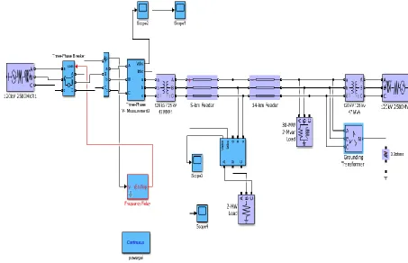
SCOPE 1: current waveform of 3-phase source SCOPE 2: voltage waveform of 3-phase source SCOPE 3: voltage waveform across load SCOPE 4: current waveform across load
Fig 1:Simulation of over/under frequency variations
During normal conditions i.e. when frequency of both 3- phase sources are within the specified range, the voltage and current waveform across load are normal. When the frequency of one of the sources is manually changed by below or above 5% range, oscillations are produced in the system which results in uneven operation of interconnected system. To prevent this uneven operation, the generator producing this abnormality is cut out using frequency relay
block. The current and voltage wave-forms across generator
producing abnormality during this abnormal operation are shown by scope 1 and 2 respectively.
[image:2.596.80.533.274.566.2]515
SCOPE 2:
SCOPE 3:
516
3 VOLTAGE VARIATIONS
The major causes of voltage variations are due to the load variations, faults and surges in a system .The voltage variations permitted in a system are ±6% whereas voltage regulation is permitted for voltage higher than 132kv is ±10% [4]. In a power system generation should be equal to summation of demand and loss to keep the system stable. The voltage can fluctuate above or below the given range hence can cause abnormality or faulty conditions. To overcome this problem, over voltage relay and under voltage relay are used.
3.1
Simulation
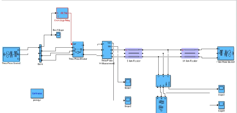
For simulation a purpose, an interconnected system has been used which consists of two
3-phase sources feeding the load, a
[image:4.596.62.553.272.507.2]OVER/UNDER VOLTAGE Relay Block [8] and a circuit breaker block. To simulate the voltage variations in the system we manually alter the voltage. This change in voltage is sensed by the under/over voltage relay block which operates only when the voltage is beyond the prescribed range of ±10% of rated voltage [10].
Fig 2: Simulation of over voltage variations
SCOPE 1: current waveform of
3-phase source SCOPE 2:
voltage waveform of 3-phase
source SCOPE 3: voltage
waveform across load
SCOPE 4: current waveform across load
517
4 Conclusion
The paper has presented the modelling of power grid SCOPE 1:
SCOPE 2:
SCOPE 3:
518
4 CONCLUSION
This paper has presented the modelling of power grid synchronization failure on sensing bad voltage or frequency. By using the programming logic, tripping of breaker at a given over and under frequency limit, over and under voltage limit has simulate in MATLAB/ SIMULINK. Due to tripping of breaker, system becomes isolated and hence protects the system against the variations.
REFERENCES
[1] B.Roberts, “Capturing grid power” IEEE power energy
Mag. Vol 7, no.4,pp 32-41, July Aug 2009
[2] IEEE Guide for Generator Protection, ANSI/IEEE
C37.101-2006.
[3] Protective Relaying for Power Generation Systems;
Donald Reimert, CRC Press 2006; ISBN #O-8247-0700-1.
[4] S.Butler “UK Electricity Networks the nature of UK electricity transmission and distribution networks in an intermittent renewable and embedded electricity generation failure.”2009.
[5] Power system Protection, 2001, Seventh International
Conference on (IEE), 2001, pp. 7073.
[6] Donald Reimert, Protective Relaying For Power
Generation System, Taylor & Francis Group, Boca
Raton,London New York,2006
[7] Rodney Tan, Modelling and Simulation of Frequency
Relay Block (ANSI/IEEE C37.2 device number 81) , 2017
[8] J.Svensson, “Synchronisation methods for Grid