1651
Productivity Optimization: a tailored Lean and Agile approach
for Automotive Propeller Shaft Assembly
Nilesh H. Khandare1, S. S. Deshmukh2
1
Research Student & Assistant Professor, Mechanical Engg. Dept, S.S.G.M.C.E Shegaon, M.S India
2
Professor & Head, Mechanical Engg. Dept, PRMIT Badnera, Amravati, M.S India 1
email- [email protected], [email protected]
Abstract: Considering present scenario of Industrialization; it has been observed that most of the Original Equipment Manufacturers belongs to MSME’s (micro, small and medium enterprise) are inadequate with state-of-art technology due to many more reasons; resulting in ceasing of technological growth, “Productivity” mainly focuses on total number of quantity produced, created, or completed. It is a count of productive competence of a machine, industry or an individual. In agile manufacturing [3],[4] requisites, productivity might not be excessively helpful as it makes a sense to measure the number of characteristics per individual or per team over the time. “Kaizen” is an approach; where workers work together to achieve regular, incremental improvements in the manufacturing process. It combines the collective ability of a organization to create an mechanism for repeatedly eliminating waste from manufacturing processes. With the implementation of the kaizen; one issue [1] on operation over machine tool was eliminated, one man two machine concepts achieved and Industrial organization achieved more than 12% increment in production.
Keywords: Productivity Optimization, Automotive Propeller Shaft, Kaizen
1. INTRODUCTION:
Automotive propeller drive shafts are the torque carriers; they are subject to torsion and shear stress which is equivalent to the difference between the input torque and the load. They must be strong enough to bear the stress, whilst avoiding too much additional weight as that would in turn increase their inertia. To allow for variations in the alignment and distance between the driver and driven components, drive shafts frequently incorporate one or more universal joints, shaft couplings and sometimes a splined joint or prismatic joint.
“Throughput” is comparative effectiveness of any manufacturing process or any operation. Throughput time is “the time between the release of a production order and the receipt of manufactured goods in inventory or the shipment of the goods to a consumer”. It can be stated as a calculation of items manufactured per unit span of the time.
By arranging the “Gemba” visits to know their production related barriers and to see how difficult the process of manufacturing is, it is observed that most of the automotive propeller shaft industries are facing lots of problems for the overall manufacturing of the propeller shafts. Most of the cars are front wheel drive, but some of the cars like Maruti Omni, Gypsy, Mahindra Bolero etc. and different SUV (Sports Utility Vehicles) are coming in the class of rear wheel drive, propeller shaft is a important component for the cars, buses, trucks because the hazard associated with is having too much importance in the field of the automobile. To know how it is most hazardous automobile component, we have to take the example of the one of the Olympic pole vaulting game of jumping a man with stick in his hand with a long run and suddenly stops
due to the long stick which he is having, all the momentum will effect to lift the sports man in the air due to sudden stoppage. The same case happening with the car or a bus, unfortunately if the propeller shaft of the vehicle breaks through the joint ends it will thrust in the surface of the road and it will tilt whole vehicle at a high speed, it may cause severe accident.
To restrict the mishap, manufacturer must pay full attention on the throughout manufacturing process of the propeller shaft, starting from the procurement of raw material by checking the quality of incoming material and monitoring the overall process by the implementation of the modern manufacturing techniques.
2. MOTIVATION
Automobile is a very vast field; technological changes are rapidly taking place in this field. Every day most of the original equipment manufacturers and multinational organizations are registering their patents in the automobile field by inventing state of art technology and equipments those will serve for society. Many accidents happened till the date due to failure of the propeller shaft and this failure is mostly due to overload of production, improper manufacturing methodology, lack of the technical awareness and non standardized workflow procedures.
3. PROPELLER SHAFT WITH REAR ENGINE AND
REAR WHEEL DRIVE
1652 send power from a central differential, transmission, or
transaxle to the wheels. This type of the system is employed in most of the three wheelers, and some of four wheelers.
4. PROPELLER SHAFT WITH FRONT ENGINE
AND REAR WHEEL DRIVE
In front engine rear wheel drive vehicles, a longer drive shaft is required to transmit the power to the wheels of the vehicle. The torque tube with a single universal joint and the more common are the Hotchkiss drives with two or more joints. Most of these vehicles have a clutch and gearbox (or transmission) mounted directly on the engine with a drive shaft leading to a final drive in the rear axle. When the vehicle is stationary, the drive shaft does not rotate, as a case of this most of the drivers prefers the gear engaged condition for parking of the vehicle so then the propeller shaft used there as for breaking means. A few mostly sport cars seeking improved weight balance between front and rear end and most commonly in the modern vehicles like Alfa Romeos etc, designers used a rear-mounted transaxle. This places the clutch and transmission at the rear of the car and the drive shaft between them and the engine. In this case the drive shaft rotates continuously as long as the engine does, even when the car is stationary and out of gear. In the Early age, automobiles often used chain drive or belt drive mechanisms rather than a drive shaft. Some used electrical generators and motors to transmit power to the wheels.
5. PROPELLER SHAFT WITH FRONT WHEEL
DRIVE SYSTEM
The "drive shaft" is restricted to a transverse shaft that transmits power to the driving wheels, especially for the front wheels. A drive shaft connecting the gearbox to a rear differential is called a “propeller shaft”. A propeller shaft assembly consists of a propeller shaft, sleeve yoke, flange yoke, stub yoke, slip stub shaft or a slip joints and one or more universal joints. The engine and axles are separated from each other, as on four-wheel drive and rear-wheel drive vehicles, it is the propeller shaft that serves to transmit the drive force generated by the engine to the axles.
6. TYPES OF AUTOMOBILE/AUTOMOTIVE
PROPELLER SHAFTS a) One Piece Propeller Shaft
One piece designs necessitate a lighter material, such as composite material, stainless steel, aluminium etc. which requires a larger diameter shaft to achieve the same strength as compare to the stock steel shafts. There are several points to remember with this approach:
A larger clearance is required to accommodate the shaft and its harmonics,
Due to angle and material, the shaft is more prone to damage,
This shaft is significantly cheaper to produce
The speed limit is low; most likely below what might seem reasonable for automotive market.
Manufacturing the same propeller shaft out of mild steel for a automotive application would be too heavy overall and would excessively put load on stress bearing, seals, etc.
b) Two Piece Propeller Shaft
A two piece shaft is used to prevent the shaft from bending at higher speeds; this is known as the “whipping effect”. As the shaft will not bend, therefore the transmission system or floor above the shaft can be lower allowing more space for the passengers or goods in case of the loading vehicle.
c) Three Piece Propeller Shaft
Three piece propeller shafts are generally employed where the distance between the automobiles transmission unit to the differential is large. For example the loading trucks and some passenger buses who is having longer chassis.
7. PROPELLER SHAFT MANUFACTURING
STAGES
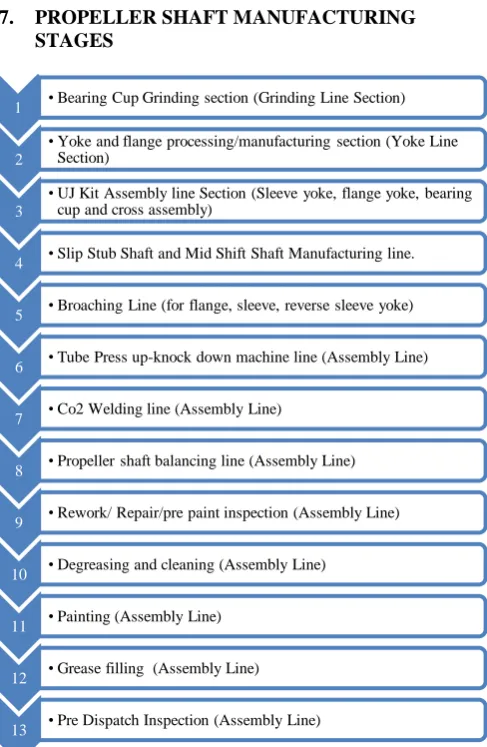
Fig. Propeller Shaft Manufacturing Stages
The propeller shaft is manufactured through the above mentioned stages. These are the most common steps mostly
1 • Bearing Cup Grinding section (Grinding Line Section)
2
• Yoke and flange processing/manufacturing section (Yoke Line Section)
3
• UJ Kit Assembly line Section (Sleeve yoke, flange yoke, bearing cup and cross assembly)
4 • Slip Stub Shaft and Mid Shift Shaft Manufacturing line.
5 • Broaching Line (for flange, sleeve, reverse sleeve yoke)
6 • Tube Press up-knock down machine line (Assembly Line)
7 • Co2 Welding line (Assembly Line)
8 • Propeller shaft balancing line (Assembly Line)
9 • Rework/ Repair/pre paint inspection (Assembly Line)
10 • Degreasing and cleaning (Assembly Line)
11 • Painting (Assembly Line)
12 • Grease filling (Assembly Line)
1653 being followed by most of the original equipment
manufacturers. There are separate manufacturing sections for each stage in propeller shaft manufacturing line;
Necessity of Lubricating The Propeller Shaft
For reducing friction between the reverse sleeve and the spline shaft, the lubricating media like grease must remains there for providing the lubricating film between the reverse sleeve and the spline shaft for reducing the friction and for this reason the stacking operation on the reverse Sleeve yoke must be carried out.
8. MATERIAL AND METHODS
As manufacturing organization finds ways to reduce waste and improve bottom line, we have considered lean and agile manufacturing [3], [4] as means for that. Manufacturing organizations could be taking a lean approach, agile approach or both the approaches. The comparison of the two, read on as Team Quality Services or sometimes even TQM [2] that is known as total quality management tool; which is nowadays very much common for most of the enterprises. Both agile and lean manufacturing are the methodological approaches generally used for lowering product costs, improving the customer service, and providing faster lead time. To enhance the production rate and morale of the associates; ergonomic developments [5] plays a vital role in overall production. For optimization of the productivity SMED [6] approach also taken into consideration.
9. EXPERIMENTAL DESIGN
A “problem” is a deviation between what should be happening and what actually is happening. That is important enough to make someone think how the deviation to be corrected. An unanticipated change produces this unwanted effect in place of the desired and expected effect. Before this unknown change occurred, things were going as expected; afterwards they are out of plan and out of control. It is strongly believed that modern competitiveness is largely based on the right management or decision and control of information. Indeed, the quality of decision-making on any problem an everyday basis and various levels of systems are indicative of the quality of information being constantly communicated. With this argument in mind, statistics are a means by which quality information can be obtained and communicated. They are a language, the means of creating and communicating quantitative concepts and ideas.
1. By providing a better understanding of process characteristics.
2. By measuring the reliability of observation made and data collected through pinpointing, what is the real problem and how one should go about solving it.
Statistics thereof do not only help control existing processes by ensuring their stability. They are the best means by which quality improvements can be achieved.
10. DATA ACQUISITION
For the identification of the major defects and problems; it is decided to accumulate the real time data from one of the leading propeller shaft manufacturing organization, the propeller shaft is manufactured with different series.
Graph –Propeller Shaft Defects and Problems Vs Occurrence Frequency
The data recorded for each batch and specific series which is mostly prone to the defects and problems.
Total number of propeller shafts taken for trial (including 1310 a1350 series) are 6783 Nos. Each and every lot for the propeller shaft is sorted according to the specific series number, the defect and the problem.
Graph –Pareto Analysis of PS assembly
1654 maintaining the quantity and quality of the propeller
shafts.
11. BEARING PRESS UP FITMENT ISSUE
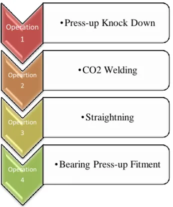
The bearing press up fitment operation was earlier carried out on dedicated conventional hydraulic press; Bearing needs to be pressed on the B.P.S. (Bearing Plug Spline) of front propeller shaft for Centre Bearing Kit Assembly. This operation will be carried out with the process flow, described in the below process flow diagram.
Fig. Bearing Press up Fitment Operation-Process Flow Chart.
12. EXPERIMENTAL CONSIDERATIONS FOR THE
TRIAL
Number of Propeller shafts considered for the trial -
1000 Nos.
Series of Propeller Shaft Considered for the Trial -
1310 and 1350
Graph: Number of P.S Vs attributes results against acceptance criteria.
13. DESIGN PHASES FOR MODIFICATION OF
BEARING PRESS UP OPERATION
Phase I- Why-Why Analysis
Why-why analysis carried out to find cause and effects relationship in the problem occurred in the propeller shaft assembly. The final solution got from the why-why analysis is to “modify the existing fixture” in the old setup of the machines. This was the crucial step towards achieving the goal.
Why to use this tool? For Process Improvement.
Why to do process improvement?
For Quality Concern.
Why quality concern? Because of Customer Complaint.
Why customer complaint Because of Bearing Press up Issues.
Why Bearing Press up issue arises?
Because of Improper fixture and Manning.
The design was initiated with noting the real time dimensions on the machine itself.
14. DESIGN PHASE II – TO PREPARE CAD MODEL
OF TRIAL FIXTURE
After design finalization the conceptual model will be formulated.
Fig. CAD 2D model of Trial Fixture
Operation 1
•Press-up Knock Down
Opeartion 2
•CO2 Welding
Opeartion 3
•Straightning
Operation 4
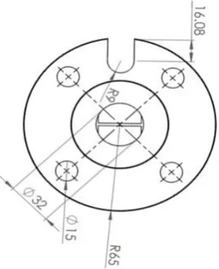
1655 Fig. CAD 2D model of Trial fixture with dimensions.
Fig. CAD 3D model of Trial fixture
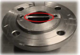
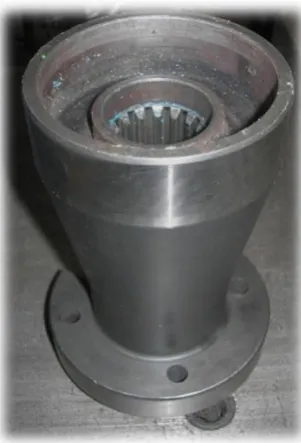
Fig. Experimental Fixture designed and manufactured.
After the implementation of trial fixture on the “Fouzak” machine; the trials were initiated by setting up the fixture with the help of the dial indicator arrangement.
The total run out checked; it is found within limit during the fastening of the fixture on the “Press up knock down” machine.
Shift Run out Value of the Trial
Fixture with machine
spindle reference (in µm)
Accepted Run
out Value (in
µm)
I 250 300
II 251 300
III 248 300
Table- Run out Value of the Run out Value of Trial Fixture
Trial Details:
Number of Propeller Shafts Considered for trial – 10/Per Shift* (*30 in total)
Series of the Propeller Shaft considered for trial – 1310 and 1350.
Graph: Propeller shaft testing results Vs No. of Propeller
Shaft for testing
1656
15. ISHIKAWA ANALYSIS FOR FIXING THE ISSUE
OF THE TRIAL FIXTURE
All the four major direct and indirect factors those are responsible for the actual method of production i.e. Man, Machine, Material, Method are taken into considerations for this Ishikawa analysis.
Fig. Ishikawa analysis- to fix Trial Fixture Issue
16. THE MODIFICATIONS TO BE CONSIDERED
FOR MODIFIED FIXTURE DESIGN-
The modified fixture must not contain any delicate position; alike it is used in earlier trial fixture.
Fixture must be compact in size and dimensions.
Design Phase –III
To prepare CAD Model with Analysis of Modified Design.
Fig. CAD 2D model of Modified Fixture
1657 Directional Deformation -ANSYS 16.0TM
By keeping one end fixed and load applied at the other end, results were encouraging in the way of manufacturing of the modified fixture.
17. DESIGN PHASE –IV
Manufacturing of Modified Fixture
Fig. Modified Fixture
This new modified designed fixture was installed on the “Press up knock down” machine. During the manufacturing of the new modified fixture; each and every loop hole what that was experienced during the manufacturing of the trial fixture; was rectified with providing the suitable fool proof solution.
Shift
Run out Value of the Modified Fixture with machine spindle reference
(in mm.)
Accepted Run out Value (in
mm.)
I 0.198 0.300
II 0.205 0.300
III 0.195 0.300
Table- Run out Value of the Modified Fixture
18. RESULTS AND DISCUSSION
New modified Fixture is fully functional and installed on press up knock down machine successfully. The trial is repeated for the validation purpose.
Trial Details
Number of Propeller Shafts Considered for trial – 1000 Nos.
Series of the Propeller Shaft considered for trial – 1310 and 1350
Shift Considered on Random Basis. Operator considered for the trial is variable. The bearing retainers considered for the trial are
100% inspected.
The graph is plotted by considering the random operator working in the random shift;
Graph: Trial on New modified fixture
Inferences from the Graph;
Out of 1000 job; only 1 Number of the propeller shaft needs rework due to the problem of the retainer damaged.
Success rate of the new modified fixture = 99.9 %. Ok Jobs- 999, Rework Jobs – 01 and Not Ok Jobs-00
End Results of Trial–
Productivity Optimization achieved is 12.2 %. Reduction in “Rework” jobs of the propeller shaft
1658 Reduction in “ Not Ok” jobs of the propeller shaft
is 6.4 %
19. CONCLUSIONS AND FUTURE SCOPE
As the propeller shaft is a critical automotive component; a proper care must be taken while manufacturing its each and every component starting for the bearing cup to tube. It is observed; if Lean and Agile approach is employed, productivity optimization with reduction in rework and rejection in process can be achieved. Even if the modern productivity optimization tools are used; there is still scope for improvements in salt spray and mud test of the propeller shaft testing.
REFERENCES
[1] David Sly et.al, (2017) “Improving the Efficiency of Large Manufacturing Assembly Plants” ELSEVIER Science direct, International Conference on Flexible Automation and Intelligent Manufacturing, Procedia Manufacturing pp 1818 – 1825.
[2] Rajesh Gautam, et.al(2012) “Kaizen implementation in an industry in India: A case study” International Journal of Research in Mechanical Engineering & Technology, ISSN: 2249-5770, Vol. 2, Issue 1.
[3] S. R. Devadasan, V. Mohan Sivakumar, R. Murugesh, P.R.Shalij, “Lean and Agile Manufacturing” PHI publications, New Delhi. ISBN-978-81-203-4611-6 [4] Hassan Soltan et.al, (2015) “Lean and agile performance
framework for manufacturing enterprises” ELSEVIER Science direct, International Materials, Industrial, and Manufacturing Engineering Conference, Procedia Manufacturing pp 476 – 484.
[5] Zelio Geraldo dos Santos et.al,(2015) “Lean Manufacturing and ergonomic working conditions in the automotive industry” ELSEVIER Science direct, International Conference on Applied Human Factors
and Ergonomics and the Affiliated Conferences, Procedia Manufacturing pp 5947 – 5954.