256
Image Inpainting Using Exemplar Based Method and
Multiscale Graph Cuts
Yogita More
1, Savita Tuplondhe
2, Dhanashree More
3, Ashwin Patil
4Department of Information Technology1, 2, 3, 4, NDMVP K.B.T.C.O.E. Nashik , Maharashtra, India1, 2, 3, 4 Email: [email protected]1
Abstract-We present a paper on exemplar – based image inpainting as a global energy minimization problem, which is written by using offset map term. Energy function includes data attachment which ensures continuity of reconstruction at the boundary of inpainting domain along with smoothness. This is adopted to obtain global minimum using graph cuts algorithm. To reduce computational complexity problem we use multiscale graph cuts algorithm . To minimize the loss of information at low resolution levels we use feature representation computed at original image resolution. This reduces ambiguity caused by comparing only color information while image is represented at low resolution levels. We show that our proposed algorithm performs better as compared with other recent algorithms.
Index Terms- Offset map; image inpainting; graph cuts.
1. INTRODUCTION
Natural images and photographs sometimes may contain stains or undesired object covering significant portions of the images. Region completion is a process in which we fill significant portions of the image by using information obtained from the remaining area of image. The filling in of missing information is very important in image processing, with applications including image restoration (e.g. scratch removal), image coding & wireless image transmission (e.g. recovering lost blocks). The object removal from images is nothing but an image manipulation technique. The purpose of region completion varies from remove-undesired object to improve the quality of image. The process of removing objects from images starts with mask out the undesired object, making the area where the object previously occupies the gap. Then the gap will be filled using graphical techniques. The graphical techniques which are used to fill the gap after object removal, in those techniques two most commonly used are: image inpainting and texture synthesis. The modification of images in a way that is nondeductible for an observer who does not know the original image. Medieval artwork stated to be restored as early as the renaissance, motives being often as much to bring medieval pictures up to date so as to fill in any of the gaps. This practice is called inpainting. The main goal of inpainting is to reconstitute the missing or damaged portions of the work, for making it more legible and also to restore its unity. Image inpainting refers to the process of changing an image so that the
change is not noticeable by an observer. Exemplar This algorithm effectively hallucinate new color values for the target region in a way that looks reasonable to the human eye.
2. LITERATURE SURVEY
In the market currently many image processing software like Adobe Photoshop, Nero Photoshop etc are available. But these software’s require knowledge of handling the software because these software’s are very complicated to use. Most of existing software’s require training for handling software. This training may be of 6 months, a year or 2 year.
Thus the users of these software’s are restricted to trained people. And there’s no facility for a common user with no programming knowledge to use image processing software to remove the object from image and video. Now a days inpainting methods are classified in two main parts:
(1) Geometry method (2) Exemplar -based method
257 geometry – oriented methods are local in sense that
they are based on PDEs. An implication of this is that, among all data available from image, they only use the information at the boundary of the inpainting domain. This frequently tends to introduce blurring artifacts in textured or large missing regions.
3. PROJECT STATEMENT
The need to develop such software can be best explained by citing the drawbacks of the presently available system or the present scenario in the market. These days lot of images and videos processing software available in the market but no image processing software has the facility to remove the object or unwanted part from image without disturbing the background of image or video. In present software’s if you remove any part from image then the background of the image cannot match and white background will remain on image after removing the object from the image. EIV is a software tool by which you can remove the object from your image and video without disturbing the background of an image or a video. It includes :
(1) Image editing – Edit the image in various way, such as by applying various effects on the image, use the paint tool operation on image such as by applying various effects on the image, use paint tool operation on image such as brush, erases, add text etc.
(2) Object removal from image – Remove the object from image without disturbing the background of image.
(3) Object removal from video-Remove the object from video without disturbing the background of the video.
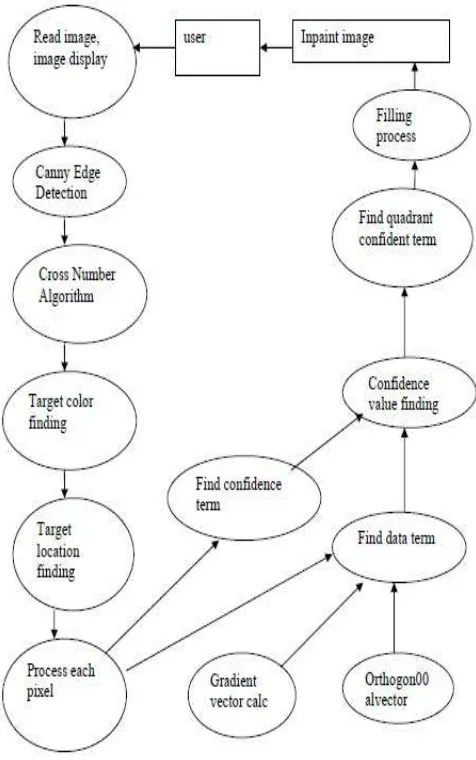
4. ARCHITECTURE
In this image to be filled is selected by the user. Here we first find the edge, then the target region to be filled. Process each pixel and find the patch that is to be filled by exemplar inpainting method. Find confidential term and data term. Data term is found by Gradient Vector and Orthogonal Vector. Find the quadrant coefficient term and fill the region by appropriate color. Overall architecture is as shown in Fig 1.
Fig. 1. Architectural Design
5. WORKING OF ALGORITHM
5.1 Criminisi’s algorithm
258 isophote into consideration, and gave higher priority
to those “interesting points” on the boundary of a gap. Those interesting points are parts of linear structures, and thus should be extended into the gap in order to obtain a naturally look. To identify those interesting points, Criminisi gives a priority value to all the pixels on the boundary of the gap. The “interesting points” will get higher priorities according to the algorithm, and thus the linear structures would be extended first. For each pixel on the boundary, a patch is constructed with that pixel at the center. The patch’s priority is the product of two elements: a confidence term C(p), and a data term D(p). C(p) describes how many pixels are there in the patch. It is obvious that with more pixels in the patch, we would have a better confidence that a success target patch would be selected. D(p) describes how strong the isophote is hitting the boundary. This term boosts the priority of a patch that an isophote “flows” into. D(p) is especially important, since it encourages linear structures to be synthesized first, and thus propagated securely into the target region.
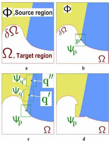
Fig. 2. Structure propagation by exemplar-based inpainting.
The user will be asked to select a target region, Ω, manually. (a)The contour of the target region is denoted as δΩ. (b)For every point p on the contour δΩ, a patch Ψp is constructed, with p in the center of the patch. a priority is calculated based on how much reliable information around the pixel, as well as the isophote at this point. (c)The patch with the highest priority, would be the target to fill. A global search is performed on the whole image to find a patch, Ψq that has most similarities with Ψp. (d) The last step would
be copy the pixels from Ψq to fill Ψp. With a new contour, the next round of finding the patch with the highest continues, until all the gaps are filled.
5.1.1 Implementation Details
The program will take in two input images: the original image and the mask image that would mask out the object. After read in the mask, we marked the target region that will be filled. Also, the contour (the boundary between the gap and the surrounding area) is defined as a collection of pixels that has a neighboring pixel in the target region. We maintain a list of contour points in the form of a vector. For each pixel in the contour, we built a patch with a given size. Then, we apply Criminisi’s algorithm to find out the target patch that has the highest priority. Then, we performed a search to find a patch in the source area that is the most similar to the target patch. In our implementation, we calculate the color distance between the non-empty patch pixels at the same position. Sum of Square Difference (SSD) is used to calculate each color channel’s difference, and then use SSD to sum up the overall color distance between the pixels. Once the best-fit patch has been found, we copy the color values from the source patch to the target patch. A target patch contains portion of source region and portion of target region. Only the pixels which are in the target region will be filled. After filling the patch, update the contour list. Those contour points that fall into the boundary of the target region will be removed from the list. At the same time, the pixels on the boundary of the target patch will be added to the contour list, if those pixels hadn’t been filled yet. This is illustrated by the Figure 2. (d). We keep select patches whose center point is on the contour to be filled. After the filling, we would update the contour list. Then, the whole target region will be entirely filled, and the contour list would be empty. At this point, we have my result picture.
259 Fig.. 4. Mask image
Fig. 5. Expected Output
Above figures shows the example of object removal from an image.
5.2. Flood fill algorithm
We use this algorithm in our paint tool box to select the object having same pixel value.
In this algorithm when we click on any point of the image then this point is passed as input to this algorithm as start point with color value of that pixel. INPUT: Start point = Click point
FILL COLOR = color value of point.
When we apply this algorithm by clicking on any point then algorithm start to fill the region in the group of surronding 8 pixel recursively.
6. RESULTS
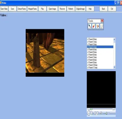
Fig. 6. Graphical user interface
260 Fig. 8. GUI of video removal
7. APPLICATIONS removing an object from video. E.g.
• You can remove the head of any person from the video and make that video very funny.
• Apply the various effects to your image and make it very beautiful. You can increase the brightness of your image, you can rotate it in any direction.
8. CONCLUSION
Thus we have used Exemplar-based algorithm for removing large objects from digital photographs and video. The result of object removal is an image in which the selected object has been replaced by a visually plausible background that mimics the appearance of the source region.
References
[1] C. Barnes, E. Shechtman, A. Finkelstein, and D. B. Goldman, “Patchmatch: A randomized correspondence algorithm for structural imageediting,” in Proc. SIGGRAPH, 2009, pp. 1– 11.
[2] D. Liu, X. Sun, F. Wu, S. Li, and Y.-Q. Zhang, “Image compression with edge-based inpainting,” IEEE Trans. Circuits Syst. Video Technol.,vol. 17, no. 10, pp. 1273–1287, Oct. 2007.
[3] F. Bornemann and T. Marz, “Fast image inpainting based on coherence transport,” J.
Math. Imag. Vis., vol. 28, no. 3, pp. 259–278,
[5] P. Arias, G. Facciolo, V. Caselles, and G. Sapiro, “A variational Fram ework for exemplar-based image inpainting,” Int. J. Comput. Vis., vol. 93, no. 3, pp. 319–347, 2011.
[6] P. Arias, V. Caselles, and G. Facciolo, “Analysis of a variational framework for exemplar-based image inpainting,” Multiscale Model. Simul., vol. 10, no. 2, pp. 473–514, 2012.
[7] S. Zinger, L. Do, and P. H. N. de With, “Free-viewpoint depth image based rendering,” J. Vis. Commun. Image Rep., vol. 21, nos. 5–6,pp. 533– 541, 2010.
[8] Y.-Q. Liu, J. Wang, and H.-H. Zhang, “Adaptive patch-based inpainting for image block recovery,” in Proc. Int. Conf. Comput. Vis. Theory Appl.,2010, pp. 52–59.
[9] Z. Tauber, Z.-N. Li, and M. Drew, “Review and preview: Disocclusion by inpainting for image-based rendering,” IEEE Trans. Syst., Man, Cybern.,C, Appl. Rev., vol. 37, no. 4, pp. 527– 540, Jul. 2007.
[10]Z.. Xiong, X. Sun, and F. Wu, “Block-based image compression with parameter-assistant inpainting,” IEEE Trans. Image Process., vol. 19, no. 6, pp. 1651–1657, Jun. 2010.
[11]Z. Xu and J. Sun, “Image inpainting by patch propagation using patch sparsity,” IEEE Trans.
Image Process., vol. 19, no. 5, pp. 1153–