Effect Of Back Pressure On Nozzle Flow
1
G.Gopi, 2Dr.B.Raghava Rao,
1
Assistant Professor, 2Professor, 1
Department of Mechanical Engineering, NNRG,Hyderabad 2
Department of Mechanical Engineering, V R Siddhartha Engineering College, VIjayawada
Abstract : Nozzle is a mechanical device used to increase the velocity by the use of pressure energy and enthalpy of the fluid. The nozzles are used in subsonic and supersonic velocity applications and it is important to know the behavior of the flow in nozzles for the effective design. Computational fluid dynamics software Fluent15.0 is used for determining the compressible flow features of a 2-D axisymmetric nozzle. Inviscid analysis is done with the variation of back pressure and the values obtained matches the theory with very low % of error. Simulation extended to know shocks and their behavior. It is observed that Shock strength increases and shock moves towards the exit of the nozzle with the increase of NPR.
NOMENCLATURE
At = Area at the throat T2 = Temperature after the shock
As = Shock location at the throat Te = Temperature at the exit M1 = Mach number before the shock ρ1 = Density before the shock M2 = Mach number after the shock ρ2 = Density after the shock Me = Mach number at the exit ρe = Density at the exit P1 = Pressure before the shock As = Area at the shock P2 = Pressure after the shock At = Area at the throat T1 = Temperature before the shock
1. INTRODUCTION
Nozzle is a mechanical device of varying cross sectional area and used to increase the velocity with the expense of pressure in incompressible fluids and by the use of pressure, enthalpy in compressible fluids.
1.1 Types of Nozzles
Nozzles can be divided into two types
1. Convergent nozzle
2. Convergent – Divergent nozzle Convergent Nozzle
In this type area of nozzle is continuously decreasing. Generally this type of nozzle used where subsonic speeds are required. Maximum Mach number obtained by the use of convergent nozzle is 1 at the throat.
Fig 1.1: Convergent nozzle Fig 1.2: Convergent –Divergent nozzle Convergent – Divergent Nozzle
This nozzle is extension of convergent nozzle. Divergent portion added after convergent to get the supersonic flows. In convergent part of the nozzle, fluid is compressed and reaches to sonic condition (Mach number is 1) at the end of the convergent portion. Area equation of nozzle as follows,
1
If the Mach number is less than one, decreasing of area causes increasing the velocity. If the Mach number is greater than one, increasing of area causes increasing the
velocity. If the sonic condition is not reached at throat, nozzle behaves as a venturi meter in which velocity is decreased at the divergent portion and getting subsonic flow at the exit of nozzle.
2. LITERATURE REVIEW
A. A. Khan et al [1] simulated the flow separation in a Convergent Divergent nozzle and observed that over expansion flow in the nozzle is quiet complex and one dimensional theory can not reveal all flow features. Using Fluent software they obtained the complex flow Features High pressure
and low velocity Inlet
Subsonic flow outlet
Subsonic Supersonic
Throat High pressure
and low velocity Inlet
like lambda shocks, Aftershocks accurately. Q. Xiao et al [2] analyzed the flow separation in a Convergent Divergent nozzle of area ratio 1.5 and conclude that flow separates symmetrically and asymmetrically for the range of 1.5 < NPR < 2.4 depending on the initial flow fields. Asymmetric flow separation captured by the computation is accurate. Static pressure is continuously expanded up to the shock and pressure increased after the shock. For the asymmetric case flow separation dominates the nozzle flow and more turbulence obtained compared to the symmetric separation. Madhu B.P et al [3] had done numerical simulation of supersonic flow in conical and contour nozzles and concluded that with the increasing of divergent angle shocks are eliminated in the diverging portion. Compared with conical nozzle, contour nozzle has more velocity at the exit of nozzle and higher flow separation. Poson Roy et al [4] analyzed Rocket engine nozzle with different convergent and concluded divergent angles and conclude that these angles and throat radius influence the static pressure in the nozzle and also concluded that with the increase of diverging angle Mach number is increased. Rabhan Haoui [5] analyzed the effect of mesh size on viscous flow in nozzle and concluded that mesh size is more important to get accurate values in the viscous flow analysis. Code is stable and gets the exact values when the grid size is very small. In viscous analysis mesh size also influence the wall stresses.
3. METHODOLOGY 3.1 Theoretical Analysis
If the properties are varied in only in one direction and the property changes in other directions neglected then the flow is consider as one dimensional flow. The flowing theoretical equations are used for solving the problems. Continuity Equation
Continuity equation based on the principle of conservation of mass.
m = ρAV = constant
Apply logarithm and differentiating above equation for steady, one dimensional flow the continuity equation is
dρ ρ
dV V
dA
A 0
Energy Equation
According to first law of thermodynamics energy equation for steady, one dimensional flow is
h 2000 ZV W h 2000 ZV Q
For nozzle work done by the nozzle is zero, no heat transfer across nozzle wall (adiabatic) and potential head at inlet and outlet of the same (Z1=Z2).
Then the energy equation is reduced to
h 2000 hV 2000 V
For a nozzle V1 <<<< V2
V 2000 h h
Mass Flow Rate
Mass flow rate along the nozzle is given by the following equation
ϒ ϒ!"
# ϒ "
Maximum mass flow rate is achieved when Mach number at the throat is 1 (sonic flow).
Properties Across Shock
Along the shock Mach number is decreased and pressure, temperature, density increases. If we consider M1 and M2 are Mach numbers before and after shocks then
M ϒ 1 M 2
2ϒM ϒ 1
Along the shock stagnation temperature is constant but stagnation pressure reduced due to irreversibility.
T T And P ' P
P1 and P2 are pressures before and after shock then
P
P 1 ϒM1 ϒM
T1 and T2 are temperatures before and after shock then
T T
( 1 ϒ) * M ( 1 ϒ) * M
As and At are the areas at the shock and throat then
A+
A,
1 M -.
2 ϒ 1/ .1
ϒ 1 2 M /0
ϒ!" # ϒ "
ρ1 and ρ2 are density before and after shock then
ρ ρ
ϒ 1 M
ϒ 1 M 2
The above equations only suitable for inviscid, one dimensional, steady flows. To get the results for viscous, unsteady and 3-D solutions we use governing equations of the flow.
4. MODELLNG
A two dimensional Convergent-Divergent nozzle by using area equation
1 2.23 3 1.5 for 0 ≤ X ≤ 1.5
1 0.223 3 1.5 for 1.5 ≤ X ≤ 3 --- Ref (6)
1.377
4.2.1 Effect of back pressure
4.1. Effect of back pressure
Variation of back pressure in C-D nozzle causes variation of flow from subsonic to supersonic flow. So it is important to maintain the back pressure properly for the efficient performance of the nozzle depending on the
application. In this analysis back pressures are varied from inlet pressure to design pressure to know the influence of back pressure on the performance of nozzle.
Parameters used for the analysis are,
Mesh size 640 x 15 Residue 1e-3
Pressure inlet 100 kPa, 300 K Pressure outlet 90 kPa to 10 kPa
Material Air (Ideal gas) Fluid Inviscid
4.2. Effect of Shock
Shock is the sudden increase in pressure. For some back pressures shocks are developed in the divergent potion of the nozzle. With variation of back pressure, the fluid properties across the shock vary considerably. So it is
important to know the variation of properties across shock at different back pressures. For this analysis selected NPR are 1.176, 1.25, 1.33, and 1.428.
Parameters used for the analysis are,
Mesh size 640 x 15 Residue 1e-3
Pressure inlet 100 kPa, 300 K
Pressure outlet 85 kPa, 80 kPa, 75 kPa, 70 kPa Material Air (Ideal gas)
5. RESULTS AND DISCUSSIONS 5.1 Results for back Pressure effect
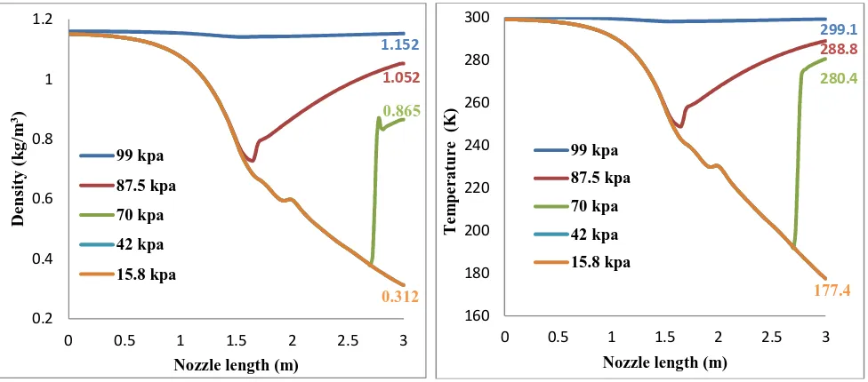
Figure 5.1(a) represents the Mach number variation through the nozzle. At the back pressure of 99 kPa, Mach number increases along the nozzle up to the throat and decreases in diverging section resulting subsonic flow. At the back pressure of 87.5 kPa, Mach number at the throat just reached to sonic condition and decreased in diverging section. For back pressures of 50 kPa shock observed in the diverging section due to sudden increase of pressure. Across
the shock Mach number is decreased. At the back pressure of 42 kPa design conditions are reached and Mach number is constant that means further decrease of back pressure will not affect the exit Mach number. Figures 5.1(b), 5.1(c) & 5.1(d) represent the corresponding pressure, density and temperature variations along the nozzle.
Fig 5.1(a) Fig 5.1(b)
1.857
0 0.4 0.8 1.2 1.6 2
0 0.5 1 1.5 2 2.5 3
M
ac
h
n
u
m
b
er
Nozzle length (m) 99 kpa
87.5 kpa
70 kpa
42 kpa
15.8 kpa
99
87.5 70
15.8
0 20 40 60 80 100
0 0.5 1 1.5 2 2.5 3
P
re
ss
u
re
(k
P
a
)
Nozzle length (m) 99 kpa
87.5 kpa
70 kpa
42 kpa
15.8 kpa 3.0
[image:3.612.66.541.469.681.2]61
Fig 5.1(c) Fig 5.1(d)
[image:4.612.63.551.90.305.2]Fig 5.1: Variation with back pressure (a) Mach number (b) Pressure (c) Density (d) Temperature Table 5.4: Comparison of theoretical and CFD values at design condition
Variable Theory CFD % Error
Mach number 1.86 1.857 0.161
Pressure (Pa) 15870 15887 0.107
Density (kg/m3) 0.307 0.312 1.628
Temperature (K) 177.33 177.48 0.084
5.2. Results For Shock Effect
Figure 5.2 shows the Mach number, Pressure, Density and temperature variation with NPR. Across the shock Mach number is decreased and becomes subsonic at the end of the shock. After the shock Mach number decreased continuously in diverging part of the nozzle. Pressure, Density and
temperature increases across the shock. The area at the shock and shock strength increases with NPR as shown in the figures 5.3 and 5.4. Figure 5.5 represents Mach number contours and from these contours clearly observes that shock moves towards exit of the nozzle with increase of NPR. 1.152
1.052
0.865
0.312 0.2
0.4 0.6 0.8 1 1.2
0 0.5 1 1.5 2 2.5 3
D
en
sit
y
(
k
g
/m
3)
Nozzle length (m) 99 kpa
87.5 kpa
70 kpa
42 kpa
15.8 kpa
299.1 288.8
280.4
177.4
160 180 200 220 240 260 280 300
0 0.5 1 1.5 2 2.5 3
T
em
p
er
a
tu
re
(K
)
Nozzle length (m) 99 kpa
87.5 kpa
70 kpa
42 kpa
[image:4.612.96.514.369.445.2]62
Fig: 5.2(a) Fig: 5.2(a)
Fig 5.2(c) Fig 5.2(d)
Fig 5.2: Variation with NPR (a) Mach number (b) Pressure (c) Density (d) Temperature
1.602
1.291 1.479
1.731
0 0.2 0.4 0.6 0.8 1 1.2 1.4 1.6 1.8
0 0.5 1 1.5 2 2.5 3
M
a
ch
n
u
m
b
er
Nozzle length (m) NPR 1.176
NPR 1.25 NPR 1.33 NPR 1.428
37.15
28.00 23.08
19.52
10 20 30 40 50 60 70 80 90 100
0 0.5 1 1.5 2 2.5 3
P
re
ss
u
re
(k
P
a
)
Nozzle length (m) NPR 1.176
NPR 1.25 NPR 1.33 NPR 1.428
0.571
0.467 0.407
0.361
0.2 0.3 0.4 0.5 0.6 0.7 0.8 0.9 1 1.1 1.2
0 0.5 1 1.5 2 2.5 3
D
en
si
ty
(k
g
/m
3)
Nozzle length (m) NPR
1.176 NPR 1.25 NPR 1.33
228.7
208.6 197.2
187.3 180
200 220 240 260 280 300
0 0.5 1 1.5 2 2.5 3
T
em
p
er
a
tu
re
(K
)
Nozzle length (m) NPR 1.176
[image:5.612.77.546.89.537.2]
Fig 5.3: Variation of Area at shock with NPR Fig 5.4: Variation of shock strength with NPR
Fig 5.5(a)
Fig 5.5 (b)
Fig 5.5(c)
Fig 5.5 (d)
Fig 5.5: Mach number variation contours with NPR (a) 1.176 (b) 1.25 (c) 1.33 (d) 1.429
6. CONCLUSIONS
1. The wide variation of velocity, pressure, temperature and density along the nozzle demands an effective design of nozzle in different applications.
2. The numerical method adopted (CFD) predicted the performance of subsonic nozzle exactly with theory (less than 1% error) and hence CFD tool can
be easily extended for any improvements or modifications in design.
3. A number of parameters influence the flow pattern in a Convergent-Divergent nozzle. The effect of these parameters can be studied using CFD technique before proceeding for the design. 1
1.05 1.1 1.15 1.2 1.25 1.3 1.35
1.1 1.2 1.3 1.4 1.5
A
s
/
A
t
NPR
0.5 1 1.5 2 2.5
1.1 1.2 1.3 1.4 1.5
S
h
o
ck
s
tr
e
n
g
th
64 4. In convergent nozzle only under expansion takes
place and that to be outside the nozzle, where as in Convergent-Divergent nozzle when the back pressure is above design value overexpansion takes place in diverging part of nozzle resulting in the form of shock waves.
5. The location and strength of a shock wave depends on back pressure and the presence of a shock is always a loss to the nozzle performance. As NPR increases the shock moves towards the exit of the nozzle.
6. The CFD methodology adopted for the prediction of shock closely matches with theoretical results with a deviation of less than 5 %.
REFERENCES
[1]
.A A Khan, T R Shembarkar. Viscous
Flow Analysis in Convergent-Divergent
Nozzle. Proceedings of international
conference on Aerospace Science and
Technology 26-28 June 2008, Bangalore,
India.
[2]
Q Xiao, H M Tsai, D. Papamoschou.
Numerical Investigation of Supersonic
Nozzle Flow Separation. AIAA journal
Vol. 45, No. 3, March 2007.
[3]
Madhu B P, Vijaya Raghu B. Numerical
Simulation of Supersonic Expansion in
Conical and Contour Nozzle. International
journal
of
engineering
research
&
Technology, ISSN-2238-0181, Vol. 3
Isssue 6, June – 2014.
[4]
Prosun Roy, A bhijit Mondal, Biswanath
Barai. CFD Analysis of Rocket engine
nozzle.
International
journal
of
Engineering Research and Sciences,
Vol-3, jan-2016, ISSN: 2349-649
[5]
Rabah Haoui. Effect of mesh size on the
Viscous
Flow
parameters
of
an
Axisymmetrc Nozzle. International
journal
of
Mechanical,
Aerospace,
Industrial,
Mechatronic
and
Manufacturing Engineering VOL: 5, No:
11, 2011.
[6]
John D Anderson, Jr. Computational Fluid
Dynamics. McGraw-Hill higher education,
ISBN 0-07-001685-2.
[7]
Cengel. Fluid Mechanics. McGraw hill
Higher Education ISBN -0-07-247236-7.