IJEDR1403011
International Journal of Engineering Development and Research (www.ijedr.org)2953
Implementation of the 5/3 Lifting 2D Discrete
Wavelet Transform
1
Jinal Patel,
2Ketki Pathak
1Post Graduate Student, 2Assistant Professor Electronics and Communication Engineering Department, Sarvajanik College of Engineering & Technology, Surat, Gujarat, India.________________________________________________________________________________________________________
Abstract - The Discrete Wavelet Transform (DWT) plays a major role in the field of signal analysis, computer vision,
object recognition, image compression and video compression standard. The advantage of DWT over other traditional transformations is that it performs multi resolution analysis of signals with localization both in time and frequency. A majority of today’s Internet bandwidth is estimated to be used for images and video. Recent multimedia applications for handheld and portable devices place a limit on the available wireless bandwidth. Wavelet based techniques such as JPEG2000 for image compression has a lot more to offer than conventional methods in terms of compression ratio. Storage of image requires higher bandwidth on the smaller devices; also image transmission requires higher bandwidth. The goal of this work is to implement the architecture of Discrete Wavelet Transform using lifting scheme for image compression applications in Xilinx and MATLAB software and then to compare the results.
________________________________________________________________________________________________________
I. INTRODUCTION
Discrete wavelet transforms (DWT) decomposes image into multiple sub bands of low and high frequency components. The two-dimensional Discrete Wavelet Transform (2D DWT) is nowadays established as a key operation in image processing. In the area of image compression, the 2D DWT has clearly prevailed against its predecessor, the 2D Discrete Cosine Transform. This is mainly because it achieves higher compression ratios, due to the subband decomposition it involves, while it eliminates the `blocking’ artifacts that deprive the reconstructed image of the desired smoothness and continuity. The high algorithmic performance of the 2D DWT in image compression justifies its use as the kernel of both the JPEG-2000 still image compression standard [1].
A 1D-DWT takes a 1-dimensional input vector and computes its wavelet transform. 2D DWT can be done easily by using 1-D DWT. To compute 2D-DWT for an image, we first apply a one-level, 1D-DWT along the rows of the image, and then apply a one-level, one-dimensional DWT along the columnof the transformed image from the first step. This divides the image into 4 parts LL, HL, LH, and HH. The LL part is a down sampled and low resolution version of the original image[4].
The paper is organized as follows: Section I the introduction of DWT and image compression is explained. Section II explains lifting scheme DWT. In Section III Lifting scheme for 5/3 wavelet filter is explained. Section IV explains Image compression parameters, Results and comparison of MATLAB and XILINX output for different images. Section V contains Conclusion. II. LIFTINGSCHEME
Lifting Scheme consists of three steps: Split, Predict and Update as shown in the fig. 1.
Split Predict Update Input
+
-Even Values
Odd Values
Low pass co-efficients
High pass co-efficients
Fig. 1 Lifting Scheme[2]
Split: In this step, the data is divided into odd and even elements.
Predict: The Predict step uses a function that approximates the data set. The differences between the approximation and the actual data, replace the odd elements of the data set. The even elements are left unchanged and become the input for the next step in the transform. The predict step, where the odd value is "predicted" from the even value is described by the equation.
IJEDR1403011
International Journal of Engineering Development and Research (www.ijedr.org)2954
difference between the odd element and its even "predictor". So in calculating an average the Update phase must operate on the differences that are stored in the odd elements.III. LIFTINGALGORITHMFORTHE5/3WAVELETFILTERS
The biorthogonal 5/3 wavelet transform is adopted in JPEG2000 standard for its simple coefficients to implement lossless compression of image, which can be factored into two stages of lifting[3].
For the conventional 5/3 filter-pair, the analysis lowpass filter h has 5 coefficients, while the analysis high-pass filter g has 3 coefficients. The filter coefficients are the following[1]:
Low-pass filter
1 2 6 2
1
:
, , , ,
8 8 8 8
8
h
High-pass filter
1
1
:
,1,
2
2
g
The 5/3 wavelet transform can be implemented by using mathematical notations as follows[3]:
( )
(2
1)
(2 )
(2
2)
H n
x n
x n
x n
( )
(2 )
( ( )
(
1))
L n
x n
H n
H n
where H(n) and L(n) represent the high and low frequency components of input signal, respectively.
From lifting scheme wavelet transform equations, it is noticed that hardware design requires only adders and shifters instead of multipliers. Figure 2 shows the lifting scheme 2-D DWT block diagram.
As shown in fig. 2, 2D lifting operation is divided into two 1D filtering operations. One for processing the data in row wise and other for processing the data in column wise. So applying lifting scheme algorithm on image, first image is divided into two parts L part and H part. Then again applying lifting scheme algorithm it is divided into four parts LL, LH, HL and HH. LL is the approximation of the image.
Split Predict Update
Split Predict Update
Split Predict Update
+
+
+
+
+
+
HH
HL
LL LH X[n]
X[2n] X[2n+1]
L H Row
Process
Column Process
Fig. 2 Lifting Scheme based 2D DWT[5] IV. SIMULATIONRESULT
There are mainly three parameters to be evaluated for Image compression. The parameters are as shown below. The main parameter is compression ratio which is the ratio of number of bits per pixel in original image to the number of bits per pixel in compressed image. The equations for compression ratio, mean square error and peak signal to noise ratio are as shown below.
IJEDR1403011
International Journal of Engineering Development and Research (www.ijedr.org)2955
1
2
Rn
C
n
2. Mean Square Error (MSE)
2
1
1
( ( )
( ))
n
c i
MSE
X i
X i
n
3. Peak Signal To Noise Ratio (PSNR)
2
(255)
10log
PSNR
MSE
Where
n= Number of image pixels
n1= Number of bits per pixel in original image n2= Number of bits per pixel in compressed image X=Original image pixel
Xc=Compressed image pixel
MATLAB OUTPUT
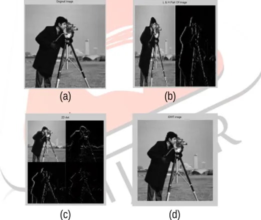
MATLAB simulation results for 1D DWT and 2D DWT are shown in fig. 3 for cameraman.tif image. Here image size is 128x128. We can see in fig. 3 that the retrieved image is same as original image.
(a)
(b)
(c)
(d)
Fig. 3 MATLAB Simulation (a) Original Image,(b) 1D DWT,(c) 2D DWT,(d) Retrieved Image
Xilinx Simulation Result
Fig. 4 Lifting split step Second Step: Predict
IJEDR1403011
International Journal of Engineering Development and Research (www.ijedr.org)2956
Fig. 5 Lifting Predict stepThird Step: Update
It updates the values which is predicted in previous step
Fig. 6 Lifting Update step
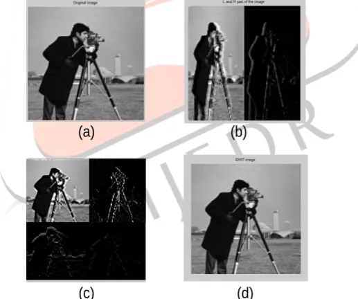
These L and H pixel values are written in file and this file can be open in MATALAB. VHDL simulation result for 1D DWT and 2D DWT are shown in fig. 7 for cameraman.tif image. Here image size is 128x128.
(a)
(b)
(c)
(d)
Fig. 7 VHDL Simulation (a) Original Image (b) 1D DWT image (c) 2D DWT image (d) Retrieved Image
So using lifting scheme algorithm, after compression perfect reconstruction of image is possible. Retrieved image is generated by applying inverse lifting scheme algorithm.
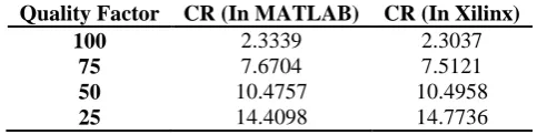
Compression ratio for different quality factor is as shown in table I. Comparison of CR(compression ratio) for 5/3 architecture in MATLAB and XILINX is shown in table I. In table I we can see that CR in both the software is almost same. In table II compression ratio for 2D Dwt is shown for different quality.
TABLE I Comparison of Compression Ratio for 5/3 Architecture(1D DWT)
Quality Factor CR (In MATLAB) CR (In Xilinx)
100 1.4195 1.3515
75 5.0771 4.9245
50 7.1111 6.9306
IJEDR1403011
International Journal of Engineering Development and Research (www.ijedr.org)2957
TABLE II Comparison of Compression Ratio for 5/3 Architecture (2D DWT)Quality Factor CR (In MATLAB) CR (In Xilinx)
100 2.3339 2.3037
75 7.6704 7.5121
50 10.4757 10.4958
25 14.4098 14.7736
V. CONCLUSION
The lifting based architecture is very simple and consists of row processor, two column processor, and memory module. The processors are very simple and consist of two adders and one multiplier. The lifting scheme DWT based 5/3 architecture for image compression is implemented in MATLAB and Xilinx. From the simulation result, as quality factor increases compression ratio decreases. For 2D DWT, compression ratio is better than 1D DWT. Using lifting scheme, perfect reconstruction of image is possible.
VI. ACKNOWLEDGMENT
I am really thankful to my guide without which the accomplishment of the task would have never been possible. I am also thankful to all other helpful people for providing me relevant information and necessary clarifications.
REFERENCES
[1] Maria E. Angelopoulou, Peter Y. K. Cheung “Implementation and Comparison of the 5/3 Lifting 2D Discrete Wavelet Transform Computation Schedules on FPGAs,” Journal of Signal Processing Systems, Springer Science,2008.
[2] K. Yamuna, C. Chandrasekhar“Design And Implementation Of Efficient Lifting Based Dwt Architecture Using Wallace Tree Multiplier For Compression,” International Journal of Engineering Research and Applications,Vol. 3, pp.1772-1777, Jul-Aug 2013.
[3] Chengyi Xiong; Jinwen Tian; Liu, Jian, "Efficient Architectures for Two-Dimensional Discrete Wavelet Transform Using Lifting Scheme," IEEE Transactions on Image Processing, vol.16, no.3, pp.607,614, March 2007.
[4] Jain, R.; Panda, P.R., "An Efficient Pipelined VLSI Architecture for Lifting-Based 2D-Discrete Wavelet Transform," IEEE International Symposium on Circuits and Systems, pp.1377-1380, May 2007.
![Fig. 1 Lifting SchemeOdd Values[2]](https://thumb-us.123doks.com/thumbv2/123dok_us/8605446.1395154/1.595.45.462.503.691/fig-lifting-schemeodd-values.webp)
![Fig. 2 Lifting Scheme based 2D DWT[5]](https://thumb-us.123doks.com/thumbv2/123dok_us/8605446.1395154/2.595.176.414.469.664/fig-lifting-scheme-based-d-dwt.webp)