Cross-Layer Design for Medium Access Control
in CDMA Ad Hoc Networks
Amit Butala
Qualcomm Inc., San Diego, CA 92121, USA Email:[email protected]
Lang Tong
School of Electrical and Computer Engineering, Cornell University, Ithaca, NY 14853, USA Email:[email protected]
Received 7 August 2003; Revised 3 May 2004
A medium access control (MAC) protocol for spread-spectrum ad hoc networks with dynamic channel allocation (DCA) is pre-sented. DCA can support large systems with a smaller number of channels by dynamically assigning channels only when a node has a packet to transmit. The protocol extends cross layer, with the scheduling at the MAC, and assignment of channels at the physical layer by means of a query. It is shown that DCA is collision free under ideal conditions. By assigning channels dynami-cally, DCA offers improved throughput normalized by available bandwidth. Analytical results are presented for the performance of the query detection and the throughput for a fully connected network.
Keywords and phrases:MAC, dynamic channel allocation, spread spectrum, query, hypothesis detection.
1. INTRODUCTION
There are several challenges in the design of medium cess control (MAC) protocol for code division multiple ac-cess (CDMA) ad hoc networks. While it is possible to ap-ply single-channel MAC protocols such as MACAW [1], DBTMA [2], and FAMA [3] to a multichannel CDMA net-work by treating channels independently, such approaches do not exploit the rich diversity of CDMA, nor do they offer an efficient utilization of available spectrum. Specifically, the classical problem of hidden/exposed nodes manifests itself differently in the presence of multiple access channels; mul-tiple data channels and a control channel can coexist using different spreading codes. If the spreading codes have good cross-correlation properties, contention on one channel does not cause interference on the other channels. The selection of a channel, from a set of channels, to transmit upon, however, is an issue that has not been well addressed in literature.
Spread-spectrum protocols were introduced by Sousa and Silvester [4]. Based on the preassignment of codes, these protocols are identified as common transmitter (CT), com-mon receiver (CR), and transmitter-receiver (TR). The CT protocol is the better suited protocol for ad hoc networks since it is less complex and requires a smaller set of spreading codes. In the CT protocol, a node may begin a transmission on the transmitters’s assigned code at any time. As there is
no feedback on the status of the node, transmissions may be scheduled to nodes unable to receive. Moreover, an a priori assignment of transmit codes is assumed for all nodes in the network. This requires that the number of spreading codes be equal to the number of nodes in the system and necessitates the use of larger than necessary spreading sequences.
MACA-CT [5] improves on the CT scheme of code al-location by the use of a control sequence over the com-mon channel. Medium access is time slotted. A node sends a request-to-send (RTS) at the beginning of a time slot and is scheduled to transmit dataonly ifthe intended receiver ac-knowledges the request with a corresponding clear-to-send (CTS). This prevents transmissions to busy nodes. Here too, an apriori assignment of transmit codes is assumed for all the nodes in the network.
relatively small neighborhoods. Longer data packets may in-crease the network throughput but require a larger spreading gain to generate the larger number of spreading codes in the channel-hopping sequence. The problem of bandwidth uti-lization remains overlooked.
A common drawback in each of the above protocols is the need for large spreading gains, which imposes a severe penalty on the bandwidth utilization.
1.1. Contributions
Detection of signals is an integral part of MAC. All control signalling-based schemes require the detection of RTS and CTS. Protocols such as DBTMA must detect the presence of busy tones. In the presence of multipath fading, such detec-tions cannot be assumed perfect; missed detecdetec-tions and false alarms may have an adverse effect on the protocol perfor-mance. Unfortunately, the problem of optimal detection for maximizing MAC throughput has not been considered.
In [7], we proposed a new MAC protocol to tackle the issue of efficient spectral utilization. Referred to as the dy-namic channel allocation (DCA), this protocol requires only a fixed number of codes irrespective of the size of the net-work. Codes are dynamically assigned using a receiver-based request detector.
In this paper, an optimal design of the request detector is presented. Assuming a Rayleigh-fading model, a Neyman-Pearson detector is used with the detection threshold opti-mized for throughput. In order to perform such an optimiza-tion, a Markov chain analysis is used to obtain the relation between the detector level and normalized throughput.
Such a cross-layer design enables us to eliminate the de-pendence of the spreading gain on the number of nodes in the network and assign channels dynamically.
1.2. Structure
The structure of the paper is as follows. In Section 2, we discuss the model assumed for ad hoc networks. Section 3
elaborates the design of the new protocol and the receiver for DCA using a binary hypothesis model for channel oc-cupancy and a busy tone backoffstrategy. InSection 4, we build a Markovian representation of a fully connected ad hoc network. Analytical bounds on the throughput of the net-work are computed and compared with our implementation of the protocol. The results of comparisons between existing multichannel protocols and DCA are presented inSection 5. Relevant conclusions and foresights into the modeling of ad hoc networks are summarized inSection 6.
2. NETWORK MODEL
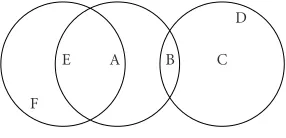
Consider a hypothetical multihop network as shown in
Figure 1. We use the protocol model definition for the neigh-borhood of a node. Thus, each node within a fixed radius (R) of the transmitter is assumed to be contained in its neighbor-hood and can listen to the transmitter. The relationship is dual; a node is not affected by any transmission that orig-inates outside its neighborhood. It is assumed that all the nodes transmit with a fixed transmit power.
F
E A B C
D
Figure1: An ad hoc network.
The network consists ofN nodes spatially distributed. Not all nodes are able to communicate with each other. The coverage areas for the nodes are represented by the circles centered at the respective nodes. Clearly, transmissions from A to B have to resolve potential contention with nodes C and E.
We assumeM+ 1 distinct spreading codes available for transmission whereMmay be less thanN. The codes are de-signed with good correlation properties [8] such that trans-missions using one code do not destroy reception on any of the other codes. As mentioned before, each code identifies a unique channel.
One of the channels is reserved for transmission of con-trol sequences while the otherM channels can support the data packets. Each node makes a choice of transmitting to a node in its neighborhood on any one of theMdata channels. Issues related to routing are not considered. It is assumed that either the nodes know the routing tables a priori or the range of communication involves only neighboring nodes.
Nodes are half duplex and can tune to only one channel at any given time. In addition, nodes also have a frequency gen-erator/receiver that may be used to transmit/receive a mono-tone on a preset frequency. This is used to specify a busy sig-nal during packet reception.
Transmission time is slotted and the transmissions are packet synchronized. The data is broken up into minipack-ets that are transmitted in succession, with each minipacket requiring one time slot. The RTS and the CTS packets are as-sumed to be less than one half minipacket in length such that an RTS-CTS packet exchange between any two nodes in the network may be completed in a single minislot.
2.1. Normalized throughput
Since the number of channels in the system that satisfy the constraints on multiaccess interference is proportional to the spreading gain, the absolute performance cannot be inferred simply by observing the raw network throughput. The net-work throughput is expected to increase with an increase in spreading gain, and hence we introduce the concept of normalized throughput for comparison of different proto-cols.
The network throughput (Γ) is defined as the average
number of packets successfully received in one time slot over the network when being in steady state. Thespreading gain
spreading gain:
η= Γ
G. (1)
Multiaccess interference can be largely eliminated if the codes are orthogonal to each other. In such codes, such as Walsh codes, the spreading gain is equal to the total number of channels available to the system. The normalized through-put would then be the ratio of the network throughthrough-put to the total number of channels. This metric is used in all subse-quent discussions to compare protocol efficiencies.
3. DYNAMIC CHANNEL ALLOCATION
Fixed channel allocation schemes discussed so far increase the number of channels required in accordance with either the size of the network or the length of the data packet. A demand-driven dynamic allocation of channels is pro-posed as one solution for overcoming this constraint. DCA relies on the assignment of one of the available data chan-nel to the nodes that get scheduled to transmit. Thus, the two basic requirements for packet exchange are scheduling of packets and allocation of channel.
Scheduling. For a successful transmission, there should be
only one transmitter attempting to transmit to a node, and any such transmission must be destined to an idle node.
This is effected by the transmission of the RTS-CTS on the control channel. Since the channel is a collision chan-nel and multiple transmissions on the same chanchan-nel result in packet collision, the RTS-CTS ensures proper scheduling of the transmissions.
Allocation. Given that two terminals are scheduled, there
must be a channel available for transmission that does not interfere with any ongoing transmission.
This is effected by a new procedure called querying of channels.
3.1. Querying of channels
The RTS-CTS control packet exchange establishes the sched-uling of packets over a particular channel, but it does not as-certain the availability of the channel. A channel is said to be available only if no node in the neighborhood of the intended receiver is transmitting on that channel, and no other node in the neighborhood of the intended transmitter is receiving on that channel. These are, respectively, the conventional ex-posed terminal and hidden terminal problems that need to be addressed in ad hoc networks. Thus, in our figure for a typical ad hoc network (Figure 1), node A may transmit to a node B on a specific channelLonly if node C (the hidden node) is not transmitting on channelLand node E (the ex-posed node) is not receiving on channelL.
Overcoming the exposed terminal problem necessitates a response from other nodes in the neighborhood (i.e., E) if it is receiving data on the same channel. The hidden terminal problem necessitates a response from B to contention due to transmission from any node in the neighborhood of B from which A might be hidden (i.e., C).
The solution is the transmission of a queryby the in-tended transmitter, A. The query is a known data packet and thus is a deterministic interference that may be estimated. Once a data transmission is scheduled using the RTS-CTS exchange, the transmitter sends out the query on the selected channel.
In response to contention, if any, caused by the query, the receiver transmits abusy tone. The busy tone is a sinusoid sent on an out-of-band frequency and intimates the trans-mitter that the channel is in use. A query is successful only if no busy tone is heard by the transmitter. This represents the case that no exposed terminal is receiving, and no hid-den terminal is transmitting, on the selected channel. A node may transmit only if its query is successful.
With the introduction of the query, in each time slot, all the nodes may be classified into the following four states.
(1) Idle(or backlogged) state: nodes that are not engaged in packet reception or transmission.
(2) Querystate: nodes that get scheduled and are
trans-mitting the query in the current time slot.
(3) Datastate: nodes involved in transmission or recep-tion of data packets. Only nodes in the data state suc-cessfully transmit data over the network.
(4) Lockedstate: an extra state that tracks nodes involved
in data packet collisions. This occurs due to a mis-detection of the query and will be discussed in more detail in the next section.
3.2. The protocol
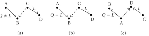
The DCA protocol is defined below and has been illustrated in Figures2,3, and4.
(1) Any idle node (e.g., A) that has a packet to transmit to any of its immediate neighbors (e.g., B) attempts to establish a communication by broadcasting an RTS on the common channel at the beginning of the minislot (Figures3and4).
(2) The RTS contains the following information: the des-tination node (B) identifier, the transmitting node (A) identifier, and the selected channel (Q) on which the data will follow. The channel Qis randomly chosen from the set of available channels.
(3) If the destination node B receives the RTS, it responds immediately, in the same time slot, with a CTS on the common channel (Figures3and4). B transitions from the idle state to the query state for the next time slot and tunes its receiver to the selected channelQ. (4) If A does not receive a CTS in the same time slot,
it times out and reverts back to the idle state. A re-transmission is attempted according to the backoff strategy. If A does receive the CTS, it moves from the idle state to the query state. This completes the scheduling.
A C
B Q=L
D L
(a)
A C
B Q=L
D L
(b)
B D
A Q=L
C L
(c)
Figure2: query for different network states: (a) success, (b) failure, and (c) failure.
A→B B→A RTS CTS
T1 T2 T3 T4 . . .
C→D channelL Busy tone Selected channelQ=L Common channel
Query Data1 Data2 . . .
. . . Data Data Data Data . . .
Figure3: Successful querying: case (a).
A→B B→A RTS CTS
T1 T2 T3 T4 . . .
C→D channelL Busy tone Selected channelQ=L Common channel
Query
RTS CTS A→B B→A
. . . Data Data Data Data . . .
Figure4: Failed querying: cases (b) and (c).
(6) The busy tone is generated in two possible cases: (i) by the intended receiver B if the queried channel
is already in use (Figure 2b);
(ii) by the contended receiver D if the selected chan-nel is already in use (Figure 2c).
(7) If A receives a busy tone on the busy-tone frequency (cases (b) or (c)), it aborts transmission on the chan-nel and reverts to the idle state (Figure 4). If A does not receive a busy tone on the busy-tone frequency, it moves to the data state and begins transmission of the data packet from the time slot that follows (Figure 3). (8) At the end of the data transmission interval, which is
an integral number of minislots, both A and B reset to the idle state.
Table 1summarizes the state transitions for the various nodes.
Lemma 1. Under the assumption of perfect detection of the query, there are no data-packet collisions.
Proof. If the detection of the query is perfect, a busy tone is
raised only if there is contention either at the query receiver or the data receiver. This is the case that the selected chan-nel is in use either for reception at an exposed node or for
Table1: DCA algorithm. Data state: transmitter
T1 Send an RTS at the beginning of the time slot. Wait for CTS.
If no CTS is received, time out and revert back to idle.
T2 If CTS is received, transmit a query on the selected channel in the next time slot.
A busy tone indicates a busy channel; abort transmission; revert to idle.
If no busy tone is heard, accept channel. T3 Transmit data packets on channel.
Idle nodes
T0 Idle nodes are tuned to common channel.
T1 If an RTS is received, decode the intended receiver. If the RTS is intended for the particular node, respond
with a CTS on the common channel. Tune to the transmitter specified channel. T2 Detect query.
If query fails, raise busy tone; revert to idle. If query succeeds, switch states to data.
T3 Receive data packets.
Data state: receiver
T0 Receivers are tuned to the transmitter’s specified channels.
T2 Raise busy tone if the presence of query is detected.
Tn Revert to idle when the transmission of the data packet completes.
transmission at a hidden node. In both cases, the intended transmitter should stop. This is the desired result of the busy tone.
In addition, the deterministic nature of the interference by the query permits data-packet decoding even in the pres-ence of the query. Thus, under perfect conditions, there is no loss of data packets due to collisions.
3.3. Detection of the query
Missed detection. In the case of a missed detection of the query, there will now be two (or more) nodes transmitting on the same channel within the vicinity of the receiver. This re-sults in a packet collision at the receiver and it is unable to de-tect either packet. The receiver and the corresponding trans-mitters are assumed to be in thelockedstate. The throughput of node pairs in the locked state is zero.
Transition of node pairs out of the locked state would depend on the coding scheme used and the higher-layer scheduling. Without imposing any additional constraints, we assume that the pair remains in the locked state till the end of the current data-packet transmission, after which they reset to the idle state.
False alarm. The false alarm induces less damage, since it
merely results in the node (i.e., A) aborting the transmission of the data packet and reverting back to the idle state. A re-transmission is attempted in accordance with the protocol. This too would lead to a decrease in the throughput of the network.
The two parameters are related, thus the optimization of the throughput requires an analysis of the receiver operating characteristics (ROC). Two types of nodes need to process a query:
(1) data state: nodes currently in reception;
(2) query state: nodes attempting to tune to the transmit-ter.
3.3.1. Detection of the query during the data state
We make the following assumptions.
(1) Each minipacket has a fixed packet size ofKbits. (2) A header ofpilot trainingbits (κK) is embedded in
each data packet to aid channel estimation and timing synchronization.
(3) The total number of data channels isM.
(4) The channel undergoes slow Rayleigh fading. The am-plitude of the fade (A) can be assumed complex, cir-cularly Gaussian, and constant over one time slot:A∼ N(0,φ2).
Then, for any particular receiver in the data state, the received signal can be written as [9]
y(t)=
M
m=1 K−1
k=0
Ambm[k]smt−kT−τm+η(t), (2)
where Am denotes the signal power on the mth channel,
bm[k] denotes thekth bit on themth channel,sm(·) is the sig-nature waveform of themth channel,τmis the timing offset of themth channel, andη(t) is the additive white Gaussian noise (AWGN) at timet.
Let the receiver be tuned into some channelL. Transmis-sions on all other channels is a secondary interference and under the interference model assumed is treated as AWGN. Transmissions on the same channel, however, cannot be ig-nored.
By the definition of the protocol, no other data transmis-sion can be on the same channel as long as the receiver is in the data state. Thus, the primary interference, if it exists, is due to the transmission of a query. Let the query be trans-mitted on channelQwhich may or may not be the same as
L. We useδQ,Lto denote the interference of the query at the
receiver. Thus,
δQ,L=
1 if query is present in the current slot and transmitted on channelL, 0 otherwise.
(3)
Then, the received signal at the output of a matched filter that is synchronized to channelLcan be represented as
y[k]=ALbL[k] +AQbQ[k]ρL,Q(τ) +bQ[k+ 1]ρQ,L(τ)δQ,L
+n[k] ∀k=1,. . .,K,
(4)
where ρL,Q and ρQ,L are the cross-correlation between the
channelsLandQon the interval over which the bitsbQ[k] andbQ[k+ 1], respectively, overlap bitbL(k), andn[k] is the filtered output of the secondary interference and the noise in thekth bit.
Detection of the query is a binary hypothesis testing problem, hence for simplicity of the receiver, we set all the bits in the query to 1, that is,bQ[k]=1. Also, assuming good correlation properties on the channels, the output signal at any receiver in the data state is
y[k]=ALbL[k] +AQδQ,L+n[k]. (5)
Thus, two hypotheses can be formulated as below.
(i) The null hypothesis (H0): the query is not on the same
channel (δQ,L=0):
H0:y[k]=ALbL[k] +n[k] ∀k=1,. . .,κ. (6)
(ii) The alternative hypothesis (H1): the query is sent on
the same channel as the data packet (δQ,L=1):
H1:y[k]=ALbL[k] +AQ+n[k] ∀k=1,. . .,κ. (7)
We assume that in the presence of a slow block fading channel, a node in the data state has already estimated the channel fade on the data link (AL). The fading on the query (AQ) is also a constant but cannot be assumed to be known by the receiver. Then, for the duration of the pilot training symbols in each packet, we can define a metric ˜y as given below:
˜
y=
κ
k=0
This simplifies our hypotheses (6) and (7) as given:
This is a standard energy detector problem. For anα-level receiver (i.e., probability of false alarmPα =α), hypothesis
H1is selected by the Neyman-Pearson detector if
|y˜|2
If the signal-to-noise ratio (SNR) is known, the power of the detector is given by
PD=2Q
3.3.2. Detection of the query during the query state
For a receiver in the query state, the queried channel is re-jected if any of the neighboring nodes transmit on the same channel synchronized with it. Analogous to (5), the model of the received signal at the receiver in the query state is
y[k]=AQ+ALbL[k]δQ,L+n[k] ∀k=1,. . .,K. (12)
Over the interval of the query, the channelAQ is a con-stant and known at the receiver. Thus, the signal error over the interval of the pilot training bits is
˜y=y−ALbL. (13)
The binary hypothesis thus simplifies as
H0: ˜y=n∼N
which again is differentiable only in one of the singular-value components. This yields exactly the same detector from the previous part.
3.4. Selection of the threshold for the detector
For the Neyman-Pearson detector, the threshold of the de-tector affects the probability of missed detection. We assume that all the nodes use the same detector operating at a thresh-old of detection. Thus, the probability of false alarm and missed detection are constant over the network and known a priori.
The throughput is a function of both the parameters, hence the optimal value of the threshold is the one that max-imizes this throughput over the ROC of the detector.
0 0.1 0.2 0.3 0.4 0.5 0.6 0.7 0.8 0.9 1
Figure5: Throughput of DCA for a fully connected network with 20 nodes, 5 data channels, and a mean data-packet length of 10 minipackets for different values of the threshold at 2 dB.
The computation of the throughput of DCA will be ad-dressed in the next section, but as an illustration, shown above inFigure 5is the throughput detector plot for a 20-node network, with 5 data channels and a mean data-packet length of 10 minipackets. The edge of the plane represents the performance of a network when the SNR is 2 dB. The op-timal point is the point on the corresponding ROC curve at which the maximum value of throughput is reached, and as can be seen, is at approximatelyPα=0.06.
4. ANALYSIS OF DCA
The analysis of a multihop network is difficult. Factors such as routing and location paging are dependent on the topol-ogy and hard to model. However, significant insight can be obtained into the performance of an ad hoc network by es-timating its performance over a fully connected network. In the next section, we simulate a few representative networks to validate our results.
The throughput of a fully connected single-hop network is analysed under the following assumption. Idle nodes have a packet to transmit with a probability p. Backlogged nodes attempt a retransmission with the same probabilityp.
The message length of the data packets is assumed to be geometrically distributed. This allows a reduction in the state space by making the model Markovian. If we takeqto be the parameter of the geometric distribution, thenP[D = d]= (1−q)qd−1, and the average packet length is given byD =
1/(1−q).
The system can now be modeled as a discrete-time Markov chain, described completely by the number of nodes in each of the four states (namely, idle, query, data, locked).
Let,
l,x=number of node pairs in the query state (in the current/previous slot);
m,y=number of node pairs in the data state;
n,z=number of node pairs in the locked state.
Also, ifNis the total number of nodes in the system, and
M is the total number of channels available, then the total number of idle nodes (N) during the given time slot is given byN=N−2l−2m−2n.
Since the system is affected by the detection probability of the query, we model the performance based on the ROC of the query detector, namely, the probability of false alarm (Pα) and the probability of missed detection (Pβ).
4.1. The state transition probabilities
The Markov chain is completely described by the number of nodes in each state. Given that the total number of nodes in the network isN, we describe each state by the three identi-fiers described above, namely,l,m,n. Consider the transition from statelmnto statexyz:
Plmn,xyz=P(x,y,z|l,m,n)
=P(x|l,m,n,y,z)P(y,z|l,m,n) =P(x|l,m,n)P(y,z|l,m,n),
(15)
where step three follows from the knowledge that the number of nodes in the query state is determined only by the state of the network in the preceding slot, or more precisely, only on the number of idle nodes in the previous slot.
4.1.1. Computation ofP(x|l,m,n)
A node pair reaches the query state if the RTS/CTS commu-nication is successful. In a fully connected network, since a maximum of one RTS can be successful in a time slot, the CTS can be granted to be always successful. An RTS is as-sumed successful if it is transmitted to an idle node. Let this event be denoted byI. Under this assumption, we compute
P(x|l,m,n), which represents the probability of an RTS/CTS exchange succeeding in the current time slot. A successful RTS/CTS exchange implies a query is attempted in the next time slot, that is,x=1:
bution of selection ofkfrom a set ofnwhen each individual probability of selection isp.
The probability of no success, that is,x=0, is
P(x=0|l,m,n)=1−P(x=1|l,m,n). (17)
4.1.2. Computation ofP(y,z|l,m,n)
Each time slot can be classified on the basis of the occurrence of four events.
(1) Query (Q): this corresponds to the event that a node transmits a query packet over one of the data channels. (2) Interference (I): this corresponds to the event that the query transmitted is on the same channel as that of one of the data transmissions.
(3) Missed detection (M): this is the event that the inter-ference of the query on the data transmission is missed by the receiving node.
(4) False alarm (F): this is the event that any one of the receivers in the data state raises the busy tone even though the query is not transmitted on the channel it is tuned to.
We compute the transitions conditioned on the presence of the query.
Ifl=0, no query was sent in the previous time slot, and no new node pair starts transmitting. Assumeinode pairs in thedatastate and j node pairs in the locked state complete the transmission, and thus revert back toidle.
P(y,z|l=0,m,n)
jlocked pairs
become idle
Ifl=1, a query was sent in the previous slot. There are four outcomes for the query: success, interference detection, false alarm, or missed detection. The probability of success-fully establishing a data channel depends on the number of available channels. Let ψD node pairs be added to thedata
state andψLnode pairs end up in the locked state in the given time slot:
jlocked pairs
Q I
M
F
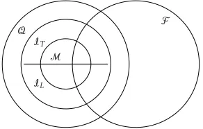
Figure6: The event space for DCA with perfect feedback of missed detections.
In the case of a missed detection, there are two nodes transmitting on the same channel within the vicinity of the receiver. This results in a packet collision at the receiver and it is unable to detect either packet. The receiver and the cor-responding transmitted are assumed to be in the locked state for the duration of the transmission.
Since our model of the state space does not carry the in-formation about the channel that gets assigned to the trans-mitter, this case needs to be tackled independently of the knowledge of the number of node pairs involved in the packet collision.
4.1.3. The upper bound
Since the nodes are half duplex, there can be no feedback from the receiver to the transmitter. An upper bound can be constructed under the assumption that a “Genie” informs the transmitter involved in a missed detection, in which case they immediately stop transmitting. In other words, a missed de-tection causes nodes to move to the idle state instead of the locked state. Hence,z=n=0 always.
Only one pair of nodes can be in the query state in any time slot. On the basis of the occurrence of the above four events, it is clear that M ⊂ I ⊂ Q. Also, since the network is fully connected, false alarms that are on an-other channel would also cause the query to fail. Thus, F andQcan be considered as independently occurring events (Figure 6).
(i) A query corresponds to the combination of events
Q∩Fc∩Ic=⇒ψD=1,ψL=0. (20)
(ii) False alarm and interference detection both result in the generation of a busy tone and the query fails. This is the combination of events
Q∩Fc∩I∩Mc∪(Q∩F)=⇒ψD=0, ψL=0. (21)
(iii) Missed detection is the event set
Q∩Fc∩I∩M=⇒ψD= −1, ψL=0. (22)
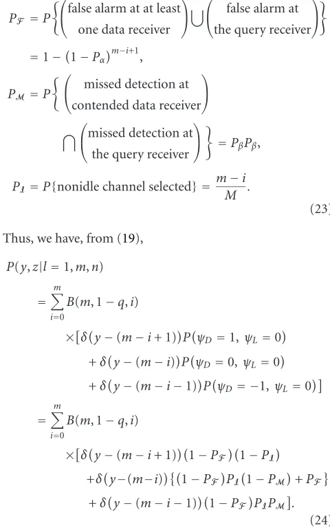
Conditioned on the arrival of the query, the probabilities for false alarm, missed detection, and interference are
PF =P
false alarm at at least
one data receiver
false alarm at
the query receiver
=1−1−Pαm−i+1,
PM=P
missed detection at
contended data receiver
missed detection at
the query receiver
=PβPβ,
PI=P{nonidle channel selected} = mM−i.
(23)
Thus, we have, from (19),
P(y,z|l=1,m,n)
=
m
i=0
B(m, 1−q,i)
×δy−(m−i+ 1)PψD=1, ψL=0
+δy−(m−i)PψD=0,ψL=0 +δy−(m−i−1)PψD= −1, ψL=0
=
m
i=0
B(m, 1−q,i)
×δy−(m−i+ 1)1−PF1−PI
+δy−(m−i)1−PFPI1−PM+PF +δy−(m−i−1)1−PFPIPM .
(24)
4.1.4. The lower bound
In the absence of feedback from the “Genie,” when a collision occurs, the transmitter does not stop transmitting. The node-pair transitions to the locked state are unavailable until the transmitter has completed its transmission.
In addition, since the state space does not carry the infor-mation of which channel the locked transmitter is transmit-ting upon, we assume that every locked node pair occupies a different channel. Clearly, this is a very conversative esti-mate and provides us with a lower bound for the system in the presence of missed detection.
Q IT
M
F
IL
Figure7: The event space for DCA with no feedback.
Thus, depending on whether the missed detection was with a node pair in the data state or already in the locked state, (ψD,ψL)=(−1, 2) or (0, 1). UsingIT to indicate that
the interference was with a channel assigned to a data node pair andILto indicate interference with a locked node pair,
we have the following (Figure 7).
(i) A query success corresponds to the events
Q∩Fc∩Ic T∩ILc
=⇒ψD=1, ψL=0. (25)
(ii) False alarm and interference detection both result in the generation of a busy tone and the query fails. This is the combination of events
Q∩F∩IT∩Mc
∪(Q∩F)=⇒ψD=0,ψL=0. (26)
(iii) A missed detection involving a channel assigned to a node pair in the transmit state is the event
Q∩Fc∩I T∩M
=⇒ψD= −1,ψL=2. (27)
(iv) A missed detection when the channel chosen is in the locked state is the event
Q∩Fc∩Ic L} =⇒
ψD=0, ψL=1. (28)
Using the above, (19) simplifies as follows:
Py,z|l=1,m,n
=
m
i=0 n
j=0
B(m, 1−q,i)B(n, 1−q,j)
×δy−(m−i+ 1)δz−(n−j) ×1−PF1−PIT∪L
+δy−(m−i)δz−(n−j) ×1−PFPIT
1−PM+PF +δy−(m−i−1)δz−(n−j+ 2) ×1−PFPITPM
+δy−(m−i)δz−(n−j+ 1) ×1−PFPIL .
(29)
4.2. Throughput
Clearly, the Markov chain is ergodic and thus a steady-state distribution exists. Let the probability of being in any state
lmn be denoted bySlmn; then the average throughputΓis equal to the number of node pairs in the transmit state weighted by the probability of being in that state:
Γ=
m
mSlmn. (30)
5. RESULTS AND SIMULATIONS
The maximum throughput of DCA is prone to the operating characteristics of the detector for the query. Peak through-put depends on both the probability of false alarm as well as missed detection. Each receiver may pick up its operat-ing point based on it is individual requirements. For simplic-ity, however, we assume that all receivers operate at the same point on the ROC. The throughput then relates to the ROC as shown earlier in Figure 5. Once the system SNR is com-puted at the receiver, the threshold of the detector is set at the point on the ROC curve that maximizes the throughput. A comparison of the three schemes discussed earlier; MACA-CT, CHMA, and DCA, is made inFigure 8for a fully connected 20-node network carrying data packets geomet-rically distributed in length and with a mean length of 10 minipackets. The number of data channels depends on the protocol. For DCA, we randomly choose 5 data channels. MACA-CT has 20 channels, determined by the size of the network. For CHMA, this number would have to be greater than the largest data packet in the network, which is infinity. We compare against the normalized throughput of modified CT, which illustrates the best case performance of CHMA for a channel-hopping sequence that is twice as long as the length of the average data-packet length (see Appendices B and C).
The normalized throughput of the 3 protocols are plotted below. The query detector for DCA is assumed to be operat-ing at 2 dB SNR.
Figure 9shows the maximum normalized throughput of DCA, at various SNR levels, compared with that of MACA-CT and CHMA. Significant performance gains are observed for the parameters indicated. Clearly, the scheme performs uniformly better for any probability of transmission and channel interference over the given bandwidth expansion available.
5.1. Parameter selection
0
Probability (p) of transimission in a slot
No
Figure 8: Normalized throughput for different schemes (Max throughput at SINR=2dB).
0.1
Figure9: Maximum throughput of DCA as a function of the SNR (L=10 andM=5).
5.1.1. Performance as a function of the number of data channels
FromFigure 10, the normalized throughput appears to be al-most monotonically decreasing beyond the addition of the first few channels. The best case performance is for systems with 2 to 4 data channels. The results are not totally
surpris-0
Figure 10: Throughput as a function of the number of chan-nels for a 20-node network with average data-packet lengthL = (a) 5 and (b) 10.
0 0.05 0.1 0.15 0.2 0.25 0.3 0.35 0.4 0.45 0.5
5 10 15 20 25 30
MACA-CT CHMA
DCA (3 channels) DCA (5 channels) DCA (6 channels) DCA (15 channels)
Mean lenght of the data packet
No
rm
al
iz
ed
th
ro
u
gh
p
u
t
Figure11: Throughput as a function of packet length for a 20-node network (at 2 dB).
of DCA is superior till the number of channels equals 8. Fixed channel allocation schemes would yield better throughput than DCA if more channels might be made available.
5.1.2. Performance as a function of the length of the data packet
As seen fromFigure 11, the throughput increases with an in-crease in the length of the data packet and then drops off. Again, this is not unexpected since longer data streams are more likely to be involved in missed detections of the query and result in locked states.
This seems to suggest that the average data packet should be kept approximately at 15 slots. Networks with differing traffic requirements might be able to achieve better perfor-mance by assigning some channels for longer data pack-ets and maintaining a nonuniform probability for selection of channels. This would entitle successful transmission of longer data streams without increasing the latency on the shorter transmissions.
Thus, the gains by DCA are more significant for networks with short data packets and fewer channels.
5.2. Transmission delay
The system delay depends, along with other factors, on the performance of the query detection and retransmission. We can however estimate the minimum delay in packet recep-tion by assuming perfect detecrecep-tion of the query. The retrans-mission policy is defined with a buffer of one packet at each node. The packet arrivals are Bernoulli with a probability p
for every idle node.
0 10 20 30 40 50 60 70 80 90 100
0 0.1 0.2 0.3 0.4 0.5 0.6
MACA-CT (12 nodes) CHMA (12 nodes) DCA (12 nodes) MACA-CT (20 nodes) CHMA (20 nodes) DCA (20 nodes )
Probability of transmission
Pa
ck
et
d
el
ay
Figure 12: Mean packet delay for DCA, MACA-CT, and CHMA with an average data-packet length of 10 minipackets (packet delay at the point of maximum throughput is denoted by “∗”).
Similar to the argument given in [6], we use Little’s theo-rem to calculate the average delay. The average delayDis the time taken for a new arriving packet to be transmitted and successfully received by the intended receiver. For a stabilized system, the arrival rate is equal to the throughput of the sys-tem (Γ). The total number of nodes (B) in the system are the nodes that are either receiving, transmitting, or having a packet to transmit:
B=
l,m,n
(N−2m−2l)p+m+l Slmn. (31)
Thus the average delay per minipacket is ¯D=B/Γ. Since
the average packet length isL=1/(1−q), the average system delay is
D=D¯L= D¯
(1−q). (32)
For light loads (p < 0.1), the protocols appear to have bounded delays. Delay for DCA is increased due to the addi-tional overhead required for the resolution of the query. The best-case performance of DCA would in fact be the curve for MACA-CT and would occur in the event that every query was successful.
0 1 2
3 4
5 6
7 8 9
10 11
12 13
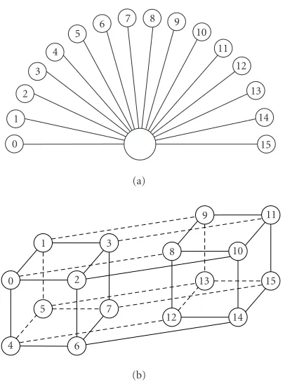
14 15 (a)
4 5
0 2
1
6 7 3
11 8
9 10
15 13
12 14
(b)
Figure13: 16-node ad hoc networks.
5.3. Multihop networks
All the above analysis is for a fully connected single-hop sce-nario. Modeling of a multihop network is difficult. However, a few reference cases were simulated to postulate the applica-bility of DCA to multihop networks and to exhibit its perfor-mance gain over existing protocols.
Figure 13ashows a fully connected network in which all the traffic is directed to the base station.Figure 13bis a multi-hop network of 16 nodes with each node having 4 neighbors [10]. The lines between the nodes show the connectivity be-tween the nodes. The throughputs using DCA and MAC-CT are shown inFigure 14.
It is interesting to note the structural dependence on the requirement of the number of spreading codes for the other protocols. In case (b), MACA-CT can be designed using a minimal of 11 data channels by taking advantage of spatial separation. For either situation, CHMA would still require as many channels as the maximal data-packet length. Both problems can be avoided by a dynamic allocation of chan-nels.
The parameters used in the simulations are identical to those used previously. We consider 5 data channels with one common control channel. Mean data-packet length is 10 slots with a geometric distribution. Nodes have a single packet buffer. The network throughput is recorded with a constant probability of packet arrival (p).
As can be seen for case (b), since the contention neigh-borhood is much smaller, the throughput of DCA is signifi-cantly greater than that for a fully connected network of the same size. Also the gains of DCA over MACA-CT are clearly visible.
0 0.1 0.2 0.3 0.4 0.5 0.6 0.7
0 0.1 0.2 0.3 0.4 0.5 0.6 0.7 0.8 0.9 1
MACA-CT (case (a)) DCA (case (a)) MACA-CT (case (b)) DCA (case (b))
Probability of transmission
No
rm
al
iz
ed
th
ro
u
gh
p
u
t
Figure14: Throughput comparisons for different scenarios.
Thus, in the context specified, DCA is superior to the other protocols and offers significant advantage. The penalty is the increased complexity of the receiver and the need for proper parameter selection. These could either be set a priori or kept variant, depending on the network load.
6. CONCLUSIONS
Medium access control is a critical issue in ad hoc net-works. One of the biggest stumbling blocks that remains is the proper scheduling and reception of data packets in the absence of a central controller. Contention of data packets occurs at the receivers, and hence proper scheduling of data packets requires the propagation of the contention informa-tion from the receivers to the transmitters. This is particu-larly interesting for multichannel ad hoc networks since the contention information can also be used in channel alloca-tion.
In multichannel ad hoc networks, the channel assign-ment has conventionally been regarded as a separate issue and isolated from the MAC. The spreading gain and conse-quent loss in the data rate are mostly overlooked.
Our objective here has been to propose a MAC protocol for multichannel ad hoc networks based on the feedback of channel contention at the receiver. A channel is selected for transmission only if it does not cause any contention at any of the receivers in the neighborhood. The protocol is proposed inSection 3.
We propose a novel method for the dynamic allocation of channels to nodes by means of querying the channel. Query-ing is a binary hypothesis detection and it is shown that the detection of the query can be modeled in terms of a Neyman-Pearson detector. The success of the hypothesis is quantized in terms of two quantities based on the signal-to-noise ra-tio at the receiver, the probability of false alarm, and missed detection of the query.
The throughput of the protocol is analysed for a fully-connected network in Section 4. Our analysis and simula-tions reveal that the network throughput is a convex function of the spreading codes, data-packet length, and the probabil-ity of transmission. The operating threshold of the query de-tection also has significant impact on the network through-put. Proper selection of network parameters is crucial in or-der to maximize the throughput.
Performance of the system for different parameters is analysed inSection 5. It is seen that for low noise conditions, DCA is superior to other protocols. DCA also manages to reduce the dependence of the protocol on the network topol-ogy thus being more versatile.
Before we conclude, it is perhaps important to note that most of the losses in DCA are the result of improper query-ing. We believe that the efficiency of the protocol can be fur-ther improved with the use of a “smart,” nonrandom channel selection policy as well as by optimizing the data state de-tectors and the query state detector to independent thresh-olds.
APPENDICES
A. MODIFICATIONS TO MACA-CT
The improvement in throughput in CHMA is due to the re-location of the CTS from the common channel to the trans-mitter’s assigned channel. Unfortunately, due to the relation between the maximum data-packet length and the hopping sequence length, it is not easy to calculate the normalized throughput of CHMA. The same technique can however be implemented without channel hopping. This may be con-sidered as an extension of MACA-CT. We call this proto-col modified CT (to acknowledge it as an extension of the CT protocols) and is introduced primarily to obtain an es-timate on the maximum normalized throughput achievable by CHMA.
B. MODIFIED CT: THE PROTOCOL
Consider a time slotted system withNnodes. Each node has a preassigned channel on which it transmits all the data pack-ets. Thus, there areNfixed data channels. In addition, there is a common control channel. Any node that has a packet to transmit sends an RTS on the control channel. The RTS specifies the transmitter, the receiver, and the transmitter’s assigned channel. This part of the protocol is exactly identi-cal to MACA-CT.
Since all the idle nodes are tuned to the common channel, if the RTS is received successfully by the intended receiver,
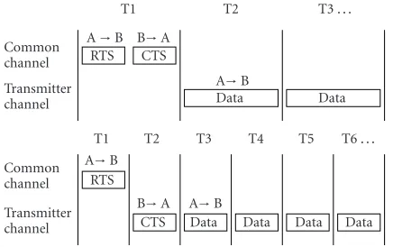
A→B B→A RTS CTS
T1 T2 T3 . . .
Transmitter channel Common channel
A→B
Data Data
A→B B→A RTS
CTS
T1 T2 T3 T4 T5 T6 . . .
Transmitter channel Common channel
A→B
Data Data Data Data
Figure15: Packet scheduling in (a) MACA-CT and (b) modified CT.
it sends a CTS to the source node over the transmitter’s as-signed channel. This is the basic difference between MACA-CT and modified MACA-CT (Figure 15). At that time, the two given nodes will proceed to exchange data over the transmitter’s assigned channel. When the transmission of the data is com-pleted, the sender and the receiver reset and tune back to the common channel.
If either multiple RTSs are sent or the destination does not receive the RTS, no CTS is sent, and consequently the source node reverts back to idle. In the absence of detection errors, the CTS always succeeds. Since the channel chosen for transmission of the data packet depends upon the transmit-ter and is not dependent on the slot number, the normalized throughput can be calculated for this case and is simply the network throughput divided by the total number of channels (N+ 1).
C. ANALYSIS OF THROUGHPUT FOR MODIFIED CT
The modified CT protocol is analysed for a single-hop fully connected network under the same assumptions made in CHMA.
For any time slot, the network can be described by (1) k: the number of nodes transmitting an RTS in the
cur-rent minislot;
(2) l: the number of nodes that sent an RTS in the previous time slot but failed the contention;
(3) m: the number of node pairs communicating on the transmitter’s assigned channel. As seen fromFigure 15, the packet will be either CTS or data.
Given a network withNnodes, any combination of these pa-rameters (k,l,m) completely describes the currentstateof the network. Also, let (w,x,y) represent identical parameters for the previous time slot.
We assume that the length of the data packet has a geo-metric distribution with a probabilityqof the data transmis-sion continuing to the next time slot. Thus, the length (D) of the packet isP(D = d)= q(d−1)(1−q). Then, the state in
Let T represent the event that the transition from (k,l,m) to (w,x,y) occurs,Ithe event that exactly one RTS is sent (i.e.,k=1) and it is sent to an idle node, andB the event that exactly one RTS is sent (i.e.,k=1) but it is sent to a busy node. The transition probabilities for the state in the Markov chain can be computed as
Pklm,wxy sents the probability that i out of them data streams ter-minate, N = N−2(m−i)−k is the number of nodes that are not transmitting or receiving at the end of the slot,
N =N−2m−l−kis the number of idle nodes for the duration of the slot, andm=y−(m−i) is the number of new node pairs that start transmitting.
The chain is aperiodic and irreducible, thus a steady-state distribution (Sklm) exists. Since the CTS is also transmitted on the data channel, it needs to be subtracted from our com-putation of the average number of packets carried per slot. The network throughput is given by
Γ=
where the first term on the right-hand side is the average number of packets carried over the data channels, and the second term represents the average number of RTS successful in one time slot. Since for every successful RTS, the CTS is al-ways successful, the difference denotes the raw data through-put. Also important to note is that the slot length for modi-fied CT is one half that of MACA-CT.
Numerical values for the throughput of modified CT are compared against that of MACA-CT and CHMA for fully connected networks of different sizes and with a mean data-packet length that is 20 times the length of the RTS (Table 2). It is seen that the network throughput of CHMA and mod-ified CT is the same. This substantiates our claim that the normalized throughput of modified CT represents a limit on the performance achievable by CHMA.
Table2: Throughput of MACA-CT, CHMA, and modified CT for networks of different sizes.
8 12 16 20
MACA-CT 1.7669 2.1521 2.4131 2.5981 CHMA 2.4148 3.2190 3.7832 4.3363 Modified CT 2.4148 3.2190 3.7832 4.3363
ACKNOWLEDGMENTS
The authors would like to acknowledge the suggestions of Gokhan Mergen, Atul Maharshi, and Mamata Desai for their constructive feedback in the development of this pa-per. This work was supported in part by the Multidisci-plinary University Research Initiative (MURI) under the Of-fice of Naval Research Contract N00014-00-1-0564 and by the Army Research Office under Grant ARO-DAAB19-00-1-0507.
REFERENCES
[1] V. Bharghavan, A. Demers, S. Shenker, and L. Zhang, “MACAW: a media access protocol for wireless LAN’s,” in Proc. Conference on Communications Architectures, Protocols and Applications (ACM SIGCOMM ’94), pp. 212–225, Lon-don, UK, August–September 1994.
[2] Z. J. Haas, J. Deng, and S. Tabrizi, “Collision-free medium access control scheme for ad-hoc networks,” inProc. IEEE Military Communications Conference (MILCOM ’99), vol. 1, pp. 276–280, Atlantic City, NJ, USA, 1999.
[3] C. L. Fullmer and J. J. Garcia-Luna-Aceves, “Floor acquisi-tion multiple access (FAMA) for packet-radio networks,” in Proc. Conference on Communications Architectures, Protocols and Applications (ACM SIGCOMM ’95), pp. 262–273, Cam-bridge, Mass, USA, August–September 1995.
[4] E. S. Sousa and J. A. Silvester, “Spreading code protocols for distributed spread-spectrum packet radio networks,” IEEE Trans. Communications, vol. 36, no. 3, pp. 272–281, 1988. [5] M. Joa-Ng and I-T. Lu, “Spread spectrum medium access
pro-tocol with collision avoidance in mobile ad-hoc wireless net-work,” inProc. Conference on Computer Communications (IN-FOCOM ’99), vol. 2, pp. 776–783, New York, NY, USA, March 1999.
[6] A. Tzamaloukas and J. J. Garcia-Luna-Aceves, “Channel-hopping multiple access,” inProc. IEEE International Confer-ence on Communications (ICC ’00), vol. 1, pp. 415–419, New Orleans, La, USA, June 2000.
[7] A. Butala and L. Tong, “Dynamic channel allocation and op-timal detection for MAC in CDMA ad hoc networks,” inProc. 36th Asilomar Conference on Signals, Systems and Computers, Pacific Grove, Calif, USA, November 2002.
[8] E. S. Sousa, “Interference modeling in a direct-sequence spread-spectrum packet radio network,” IEEE Trans. Com-munications, vol. 38, no. 9, pp. 1475–1482, 1990.
[9] V. Sergio, Multiuser Detection, Cambridge University Press, New York, NY, USA, 1998.
Amit Butalareceived the B.S. degree from the Indian Institute of Technology, Mum-bai, India, in 1999, and the M.S. degree in electrical engineering in 2001 from Cor-nell University, Ithaca, New York. His areas of interest include ad hoc communications, coding theory, and spread-spectrum com-munications. He is currently with Qual-comm Inc., Campbell, California.
Lang Tongis a Professor in the School of Electrical and Computer Engineering, Cor-nell University, Ithaca, New York. He re-ceived the B.E. degree from Tsinghua Uni-versity, Beijing, China, in 1985, and the M.S. and Ph.D. degrees in electrical engineering in 1987 and 1990, respectively, from the University of Notre Dame, Notre Dame, In-diana. He was a Postdoctoral Research Affi l-iate at the Information Systems Laboratory,