R E S E A R C H
Open Access
An optimization routing protocol for
FANETs
Hua Yang
*and Zhiyong Liu
Abstract
With the wide-ranging application of mobile ad hoc networks, flying ad hoc networks (FANETs) have received more and more attention from the industry. Routing technology is a key technology of ad hoc networks. The high-speed mobility of nodes poses a greater challenge to FANET routing technology. Based on the Dynamic Source Routing (DSR) protocol, the continuous Hopfield neural network is used to optimize the route to be adapted to the high-speed movement of the FANET node. In a simulation using NS3, the result shows that the optimized DSR protocol has greatly improved key indicators such as end-to-end average delay, throughput, and packet delivery ratio.
Keywords:FANET, MANET, Routing protocol, Neural networks
1 Introduction
In the past, mobile ad hoc networks (MANETs) had been applied more and more, and have expanded into the air to form flying ad hoc networks (FANETs) [1]. As an improved mobile ad hoc network, FANETs use the aircraft as a node for transmitting, receiving, or forward-ing over the air wireless communication. It can set up a network at any time and any place without any fixed fa-cilities and realize a multi-aircraft system. The network layer is effective communication. The FANETs have the commonality of traditional MANETs, such as no center, multi-hop, self-organization, and self-healing, but are also given their specific design goals and network char-acteristics. The characteristics of the aircraft nodes are fast, maneuverable, and complex in the flight environ-ment and the high degree of confrontation. It will lead to restricted bandwidth of the communication transmis-sion link, frequent switching changes, and high error rate. The network topology has dedicated time-varying and significant dynamic, so FANET routing design is also more difficult and at the same time very challenging.
Routing protocols [1–6] have always been the core
technology in various types of wired networks and wire-less networks, and are also research hotspots. For the highly dynamic FANETs, the strong mobility of a node
may easily lead to route breaks, which will trigger rout-ing updates frequently, generate a large amount of con-trol overhead in the network, cause route convergence difficulties, increase data forwarding delay, and increase packet loss rate, and even the routing protocol is invalid. In order to realize reliable and effective networking of high dynamic nodes, routing protocols are one of the key issues that need to be solved in FANETs. The same as the MANET routing, the FANET routing protocol should also have the ability to self-organize and self-heal. At the same time, the FANET routing protocol also needs to adapt to frequent changes in the network topology brought by the high-speed movement of nodes. Compared with MANETs, nodes in FANETs have higher moving speed, and their routing is the most likely to break in the communication process. Although the
trad-itional meaning of MANETs’ routing also considers the
moving speed of nodes, it cannot be directly trans-planted to FANETs with high moving speed. In the meantime, it is necessary to ensure the corresponding improvements or redesigns in conjunction with the ac-tual situation of FANETs.
2 Related work
2.1 Overview of FANET routing protocol
At present, the industry does not have a proprietary routing protocol for FANET, and its main routing proto-col still uses the routing protoproto-col of MANETs. MANET routing protocols [7–10] can be divided into different
© The Author(s). 2019Open AccessThis article is distributed under the terms of the Creative Commons Attribution 4.0 International License (http://creativecommons.org/licenses/by/4.0/), which permits unrestricted use, distribution, and reproduction in any medium, provided you give appropriate credit to the original author(s) and the source, provide a link to the Creative Commons license, and indicate if changes were made.
* Correspondence:[email protected]
types according to different classification criteria. Ac-cording to the route discovery strategy, it is divided into reactive routing, proactive routing, and hybrid routing.
2.1.1 Reactive routing
This type of routing protocol creates a route only when the source node needs to communicate, and does not need to maintain the routing information of all nodes in real time like a table-driven routing protocol. Therefore, such routes are known as on-demand routing protocols. This type of routing protocol has poor stability in highly dynamic networks and is also less secure, for example,
Dynamic Source Routing (DSR) [11–13] and ad hoc
on-demand distance vector (AODV) [11,14,15].
2.1.2 Proactive routing
According to the characteristics of MANET, based on the wired network routing protocol, all nodes maintain a rout-ing table that contains routrout-ing information from this node to other nodes. When the network topology changes, the node maintains the routing table updated by exchanging routing information, so the routing table can accurately re-flect the network topology information. Because of FANETs, high-speed movement of nodes causes network topology to change very frequently, such routes are not suitable for use in FANETs, for example, Optimized Link State Routing Protocol (OLSR) [11, 16, 17] and Destination-Sequenced Distance Vector (DSDV) [11,18].
2.1.3 Hybrid routing
This type of routing algorithm uses both active routing and on-demand routing. It divides the network into do-mains and uses active routing and reactive routing pol-icies within and between domains, for example, Zone Routing Protocol (ZRP) [11,19].
In the above main routing protocols, the DSR has low overhead and rapid response to network topology changes and can provide fast response services to ensure that data packets can successfully reach the destination node. Therefore, it is more suitable for FANETs with fast node movement and strong topological changes. Based on the DSR, it is optimized based on CHNN, and the ex-pected route is more suitable for FANETs, thereby im-proving the performance of FANETs.
2.2 DSR protocol
DSR [12] is a topology-based reactive routing protocol that uses active caching strategies and extracts topology information from source routes. The node can obtain the route to all the downstream nodes from the data-gram header and can also derive more topology informa-tion by combining multiple pieces of informainforma-tion. In addition, in the network interface mode of the setup node, by listening to the route used by the neighbor
node, it is possible to obtain more topology information, and more and more network topology information is stored in the cache to improve the cache hit rate of the route lookup. So, it can reduce the frequency of routing discovery process and save network bandwidth. DSR mainly includes route discovery and route maintenance.
2.2.1 Route discovery
When the communication node needs to transmit packet data, the route discovery process checks whether the node itself contains the destination and routing in-formation for the initialization data. If it has, the route is initiated to establish a connection. Else, the route is initi-ated to establish a flood routing the request to deter-mine whether the destination node exists. If it exists, the routing response is sent. The source node receives the response to establish a connection. If there is no destin-ation node, it determines whether the routing informa-tion to the destinainforma-tion node is cached. If sure, routing response is sent, and the source node receives the re-sponse to establish a connection. Else, it determines whether the maximum hop count reached restrict, and then return to search again. If the limit reached, the route fails to establish a connection. When the routing connection is interrupted, the node will send an error packet to the source and the notice in reverse. At this point, the route discovery process is completed.
2.2.2 Route maintenance
After the route is established using the route discovery, a routing table will exist in the source node, and the data transmission will be performed according to the routing table. During the process of transmitting the data, the established route has to be maintained to be continu-ously available. By maintaining the routing table, the source node can monitor the network topology and dis-cover changes in the network topology in time to deter-mine whether the route to the destination node is continuously available. When a node in the network detects a route break, the node will send a route error packet, and the node who receives the error packet then caches it and deletes the route information. If the source node in a com-munication receives a route error packet, it deletes the route and the route discovery process is started.
2.3 Hopfield neural networks
network (CHNN) and discrete Hopfield neural network (DHNN).
CHNN mainly solves the combinatorial optimization problem; Hopfield and Tank realize that with this basic neural network organization form, by selecting the weights and external inputs that can properly represent the function to be minimized and the desired state, it is possible to calculate the specific solution and the method of optimizing the problem. Updating neurons based on differential equations ensures that energy func-tions and optimization problems can be minimized at the same time. The analog nature of the neurons and the hardware implementation of the update process can be combined to create a fast and powerful solution. The key to solving various combinatorial optimization prob-lems with neural networks is to map the problem into a neural network dynamic system and to write the corre-sponding energy function expressions and dynamic equations. They should satisfy the constraints of the problem. Finally, the neural network is studied. The dy-namic process ensures that the steady-state output of the network corresponds to the minimum value of the energy function and the solution to the combinatorial optimization problem.
The features of the Hopfield neural network are as follows:
(1) All neurons are both an input and an output, forming a single-layer fully connected recursive network.
(2) The synaptic weight of the network is different from other neural networks obtained through supervised or unsupervised iterative learning, but is calculated according to certain rules when building the network, and the weight of the network is
iterated throughout the network. No longer changing in the process.
(3) The state of the network changes with time, and the output state of each neuron at timetis related to its ownt-1 time.
(4) Introduce the concept of energy function to judge the stability of network iteration, that is, the convergence of the network, that is, the energy function reaches a minimum value.
(5) The solution of the network, that is, the state set of each neuron when the network runs to stability.
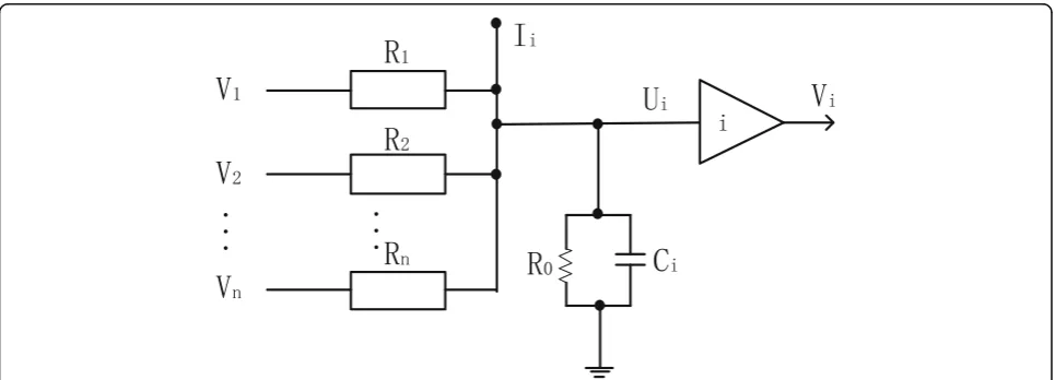
The circuit topology structure of CHNN is shown in Fig.1, whereUirepresents the input voltage of the
elec-tronic amplifying component,Vi represents the output
voltage, and operational amplifier i represents the ith
neuron.
Its state equation is
Ci
dui
dt ¼
Xn
j¼1
Tijvj−
Xn
j¼1
Tijuj−Ti0uiþIi ð1Þ
Ci
dui
dt ¼
Xn
j¼1
Tijvj−
Xn
j¼1
Tijuj−Ti0uiþIi ð2Þ
where the input voltagevisatisfies the nonlinear
map-ping rulef:
vi¼ fið Þui ð3Þ
CHNN uses the energy function to measure the stabil-ity of the network, which is defined as:
E¼1
Routing performance directly determines the perform-ance of FANETs, and routing metrics directly determine the performance of the route. In ad hoc networks, due to frequent changes in the topology, the routing protocol usually considers that there are routes for communica-tion, and does not consider the quality of the route. Therefore, the minimum hop becomes the main route metric. However, the hop count does not directly reflect the quality of the route. The result is that the hop count is the smallest, but the performance of the route is the worst.
In order to make the design of routing metric reflect the quality of routing, in the design of routing metric, we cannot rely solely on hop, link capacity, link stability, node energy, node performance, interference, node power, and other link and node factors; all need to be in-cluded. If the communication route only contains the hop count and does not consider other factors such as link stability, it is easy to cause the route to be broken due to frequent changes in the topology, causing the network to generate a high retransmission rate and caus-ing high delay of the network, resultcaus-ing in some nodes. The energy is consumed unnecessarily, which in turn af-fects the performance and longevity of the network. A reliable route is often determined by the stability of the link in ad hoc networks, so the design of the routing metric need to fully consider the stability of the link.
3.2 Definition of link stability
Let i and j be any two adjacent nodes in the network,
and Dis its communication distance. Assuming that the
nodes are of the same type, the transmit power is the same, which also determines the effective communica-tion range (set to D0). Let the stability of the link be-tween nodes be represented by Sij, which is related to
the effective range of communication and the distance between nodes, as defined below.
Sij¼ not communicate directly, andSijis 0. Conversely, nodes
can communicate directly, withSijbetween 0 and 1. Link
stability prediction is based on the wireless propagation
model. The wireless propagation model reveals the rela-tionship between radio wave transmit power, received power, and propagation distance. When the two wireless nodes are in a very close position, the Friis model is closer to the actual situation. The two-ray model is more applicable when the two wireless nodes are farther away. In general, the nodes of wireless communication are far apart, so the two-ray model is used.
Pr¼
PiGiGrðhihrÞ2
D4 ð6Þ
In the formula, Pi represents the transmission power,
Pr represents the received power, Gi represents the
transmit antenna gain,Grrepresents the receive antenna
gain, hi represents the transmit antenna height, and hr
represents the receive antenna height. It has been set thatPiis a constant, and assuming that the node uses a
directional antenna,GiG(rhih)2is a constant expressed in
k1. Thus, D can be obtained by the transformation of
Eq. (6):
Let the lowest received power of the node be P1, and
the corresponding distance is the node effective commu-nication range D0, then k1Pi = P1D04 can be obtained
from Eq. 3, and the calculated distance D can be
ob-tained by substituting into Eq. (7):
D¼4 culated link stabilitySij.
Sij¼
Whether in MANETs or FANETs, routing finds an opti-mized source-to-destination communication path in a set of wireless nodes {N1,N2,...Nn}. In order to map
network. So the key to solving the problem is to con-struct a suitable neural network energy function.
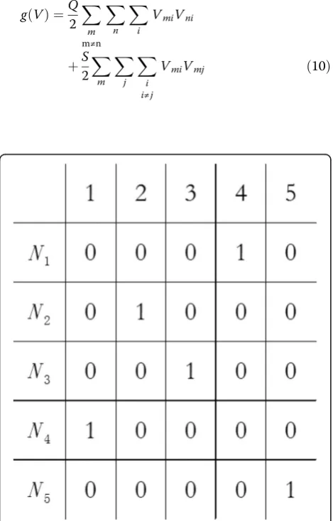
In order to optimize the CHNN routing of the FANET, the appropriate expression of the route must be found first. A route is an ordered arrangement, which has a source node, some of the intermediate nodes, and the des-tination node; the intermediate nodes can be represented
in the form of n-dimensional vectors. In FANET, there
have n intermediate nodes, and the required vector
di-mension isn−2, such as there is a matrix representation of 5 intermediate nodes (Fig.2). In Fig.2, the only route is shown:Source - > N4- > N2- > N3- > N1- > N5- >
Destin-ation. For every possible route, every intermediate node can only reach once, so each row and column in this square can only have one element with 1 and the remaining elements with 0. This is the constraint of the routing problem. Every route with the above constraints can be represented by a transposition matrix. So, the first two terms of the energy function are set to
g Vð Þ ¼Q
UsingRSDto represent the integrated distance from the
nodeSto nodeD, the Fig.2total length of the route is
RSD ¼RS4þR42þR23þR31þR15þR5D ð11Þ For FANETs, routing cannot pass through each inter-mediate node. The size of the matrix must be set to an upper limit. When there are too many intermediate nodes, it is considered unreachable. Referring to the RIP routing protocol in the wired network, set ton= 16, the energy is the third function of the function is described as:
h Vð Þ ¼T
In order to contain the effective solution route length information, the fourth term of the energy function is
f Vð Þ ¼P
Therefore the total energy function can be expressed using the following equation:
E¼f Vð Þ þh Vð Þ þg Vð Þ ð14Þ
The parameters Q, S, T, and P are called the weight, the first three items are the constraints that satisfy the route replacement matrix, and the last one contains the optimization objective function item.
In order to simplify the calculation, there is a need to ignore the integral subitem of the energy function, and then the neural network connection weight can be expressed as:
Calculate the increment of the input state using the CHNN dynamic equation:
Update the output state of the neural network at the next moment by the sigmoid function:
Fig. 2Use matrix to represent five nodes FANET routing. Use matrix to represent five nodes FANET routing; the only route is shown:
Vmi¼ f Uð miÞ ¼
1 2 1þth
Umi
U0
ð17Þ
Penalty parameters S, Q, T, and P need to be fixed
values. Hopfield [20] uses the set of parameters S = Q = P = 500,U0= 0.02to balance these terms.
4 Simulation results and discussion
4.1 Simulation platform
In order to verify the effectiveness of CHNN-optimized routing, we simulated the FANET scenario to simulate the DSR and CHNN-DSR. We mainly analyze and com-pare the following parameters that determine routing performance [25,26]:
(1)Average end-to-end delay:Defined as the average of the packet delays for all successful delivery of the entire network. Its calculation formula is
Delay¼1 n
Xn−1
i¼0
piðTreceiveÞ−piðTsendÞ
ð Þ ð18Þ
where pi represents the ith packet and n indicates the
total number of successfully delivered packets.
(2)Packet delivery ratio:Defined as the number of packets accepted by the destination node and the number of packets transmitted by the constant bit rate (CBR) source. Its calculation formula is
Delivery Ratio¼
P
DeliveryData
P
TransmiteData ð
19Þ
(3)Throughput:Defined as the average of the amount of data (kb/s) successfully delivered by each pair of communicating parties in the network per unit time.
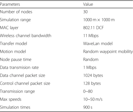
4.2 Parameter settings
The simulation software uses the NS3 simulation system (https://www.nsnam.org/) [27]. The CHNN code is de-veloped in C++ and can be directly applied to the NS3 system. When 30 nodes in the network start to simulate, they are evenly distributed in the area of 1000 m × 1000 m. The internode communication uses a CBR stream, and the data packet length is 1024 bytes. The MAC layer protocol uses IEEE 802.11 DCF. The transfer model uses
Lucent’s WaveLan. The motion model adopts a random
waypoint mobility model. The simulation runs for 900 s. See Table1for detailed settings.
4.3 Results and discussion
In order to make the results more realistic, the simula-tion is performed multiple times and then the method of
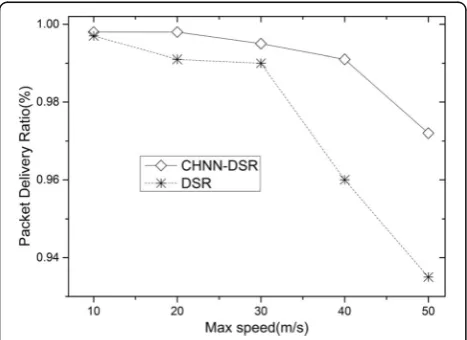
averaging is performed. Figures 3, 4, and 5 show the
comparison of the average end-to-end delay, packet de-livery ratio, and throughput of CHNN-DSR and DSR when the speed of the node movement increased. The results show that node mobility has a great impact on the routing in FANETs. In the case of high-speed mobil-ity, the route interruption may occur very frequently. Therefore, the use of optimized routing in the route dis-covery process will effectively improve the stability of the network.
From Fig.3, we can see that as the node moves faster, the average end-to-end delay increases. DSR uses source routing and storage routing, but the topology changes drastically cause source routing breaks and storage routes to failure. The risk is also increased, and CHNN-DSR uses optimized source routing, which has higher stability itself, so the probability of re-initiating route lookup is lower, and the communication quality is more secure.
From Fig.4, we can see that as the node moves faster, the packet delivery ratio also decreases. The reason is that the route through CHNN-DSR is optimized and its stability is strong, so the packet delivery ratio can always be maintained at a higher ratio. It is worth noting that although the speed increases and packet delivery ratio decreases, the route delivery ratio of both routes is above 90%, indicating that DSR is still a better choice for FANETs.
Table 1Network parameter setting
Parameters Value
Number of nodes 30
Simulation range 1000 m × 1000 m
MAC layer 802.11 DCF
Wireless channel bandwidth 11 Mbps
Transfer model WaveLan model
Motion model Random waypoint mobility
Node pause time Random
Data transmision rate 1 Mbps
Data channel packet size 1024 bytes
Control channel packet size 128 bytes
Transmission range 0~80
Max speeds 10~50 m/s
From Fig.5, we can see that as the node moves faster and the throughput performance is getting worse and worse. The optimized CHNN-DSR performance is obvi-ously better than the DSR. This is because the DSR does not remove any mechanism of outdated invalid routing, and it is not determined. The freshness of each route is used to select the correct routing mechanism after the communication route fails, and the CHNN-DSR has a lower probability of routing failure than the DSR be-cause of its strong stability.
5 Conclusions
It is feasible to apply artificial intelligence algorithms such as neural network algorithms to FANET routing optimization. In highly dynamic FANETs, the stability of
the route determines the stability of the network. Based on CHNN, the DSR is optimized and named as CHNN-DSR, which obtains a more stable and stable route, which improves the stability of FANET and the communication efficiency of the network. The simula-tion results show that in the FANETs using CHNN-DSR, the key indicators such as packet delivery ratio, end-to-end average delay, and throughput are better than those directly using DSR. In the subsequent re-search, the application of artificial intelligence algo-rithms such as neural network algoalgo-rithms to the design of FANET routing will be worthy of further research.
Abbreviations
AODV:Ad hoc on-demand distance vector; CBR: Constant bit rate; CHNN: Continuous Hopfield neural network; DHNN: Discrete Hopfield neural network; DSDV: Destination-Sequenced Distance Vector; DSR: Dynamic Source Routing; FANET: Flying ad hoc network; MANET: Mobile ad hoc network; OLSR: Optimized Link State Routing; ZRP: Zone Routing Protocol
Acknowledgements
This work is supported by Guangxi Colleges and Universities Key Laboratory of Robot & Welding.
Funding
The Science and Technology Research Project of Department of Education of Guangxi (Grant:2019KY0815)
Availability of data and materials Not applicable.
Authors’contributions
This manuscript is mainly completed by YH and LZY. YH designed an improved algorithm and simulated it. YH and LZY analyzed the simulation results. YH wrote this manuscript, LZY checked and reviewed the manuscript. Both authors read and approved the final manuscript.
Competing interests
The authors declare that they have no competing interests.
Fig. 3Average end-to-end delay simulation results for DSR and CHNN-DSR. The simulation results of the average end-to-end delay for CHNN-DSR and DSR under the change of node
movement speed
Fig. 4Packet delivery ratio simulation results for DSR and DSR. The simulation results of the packet delivery ratio for CHNN-DSR and CHNN-DSR under the change of node movement speed
Publisher’s Note
Springer Nature remains neutral with regard to jurisdictional claims in published maps and institutional affiliations.
Received: 13 February 2019 Accepted: 18 April 2019
References
1. I. Bekmezci, O.K. Sahingoz,Ş. Temel, Flying ad-hoc networks (FANETs): a survey. Ad Hoc Netw..11(3), 1254–1270 (2013)
2. V. Sharma, R. Kumar, G-FANET: an ambient network formation between ground and flying ad hoc networks. Telecommun. Syst.65(1), 31–54 (2017) 3. A.V. Leonov, Application of bee colony algorithm for FANET routing. In:
2016 17th International Conference of Young Specialists on Micro/ Nanotechnologies and Electron Devices (EDM), Erlagol, Russia, pp. 124–132 (2016).https://doi.org/10.1109/edm.2016.7538709.
4. M. A. Khan, A. Safi, I. M. Qureshi, I. U. Khan, 2017. Flying ad-hoc networks (FANETs): A review of communication architectures, and routing protocols. In 2017 First International Conference on Latest trends in Electrical Engineering and Computing Technologies (INTELLECT). 1-9.https://doi.org/ 10.1109/INTELLECT.2017.8277614.
5. W. Zafar, B.M. Khan, A reliable, delay bounded and less complex communication protocol for multicluster FANETs. Digit Commun Netw3(1), 30–38 (2017) 6. A. Bujari, C.E. Palazzi, D. Ronzani, in Proceedings of the 3rd Workshop on
Micro Aerial Vehicle Networks, Systems, and Applications. FANET application scenarios and mobility models (ACM, 2017), pp. 43–46.https://doi.org/10. 1145/3086439.3086440.
7. J. Macker,Mobile Ad Hoc Networking (MANET): Routing Protocol Performance Issues and Evaluation Considerations(1999)
8. F. Bai, N. Sadagopan, A. Helmy, Important: a Framework to Systematically Analyze the Impact of Mobility on Performance of Routing Protocols for Adhoc Networks. In: Proceedings of INFOCOM 2003, San Francisco, CA (2003)
9. M. Abolhasan, T. Wysocki, E. Dutkiewicz, A review of routing protocols for mobile ad hoc networks. Ad Hoc Netw.2(1), 1–22 (2004)
10. F. Bai, N. Sadagopan, A. Helmy, The IMPORTANT framework for analyzing the Impact of Mobility on Performance Of RouTing protocols for Adhoc NeTworks. Ad Hoc Netw.1(4), 383–403 (2003)
11. A. Singh, G. Singh, M. Singh, inIntelligent Communication, Control and Devices. Comparative study of OLSR, DSDV, AODV, DSR and ZRP routing protocols under blackhole attack in mobile ad hoc network (Springer, Singapore, 2018), pp. 443–453
12. D.B. Johnson, D.A. Maltz, inMobile computing. Dynamic source routing in ad hoc wireless networks (Springer, Boston, 1996), pp. 153–181
13. H. Yang, Z. Li, Z. Liu(2019). A method of routing optimization using CHNN in MANET. Journal of Ambient Intelligence and Humanized
Computing, 10(5), 1759-1768.
14. C. Perkins, E. Royer, Ad hoc on-demand distance vector routing, in: IEEE WMCSA'99(1999).
15. H. Yang, Z. Li, Z. Liu, Neural networks for MANET AODV: an optimization approach. Clust. Comput.20(4), 3369–3377 (2017)
16. T. Clausen, P. Jacquet,Optimized link state routing protocol (OLSR) (No. RFC 3626)(2003)
17. Y. Wu, L. Xu, X. Lin, J. Fang, inInternational Conference on Internet of Vehicles. A new routing protocol based on OLSR designed for UANET maritime search and rescue (Springer, Cham, 2017), pp. 79–91
18. C. Perkins, P. Bhagwat, Highly dynamic destination-sequenced distance-vector routing (DSDV) for mobile computers, in: ACM SIG-COMM Symposium on Communication, Architectures and Applications (1994). 19. Z.J. Haas, M.R. Pearlman, P. Samar,The Zone Routing Protocol (ZRP) for Ad
Hoc Networks(2002)
20. J.J. Hopfield, Neural networks and physical systems with emergent collective computational abilities. Proc. Natl. Acad. Sci.79(8), 2554–2558 (1982) 21. J. Zhang, X. Jin, Global stability analysis in delayed Hopfield neural network
models. Neural Netw.13(7), 745–753 (2000)
22. G. Rajchakit, R. Saravanakumar, C.K. Ahn, H.R. Karimi, Improved exponential convergence result for generalized neural networks including interval time-varying delayed signals. Neural Netw.86, 10–17 (2017)
23. C. Zhong, C. Luo, Z. Chu, W. Gan, (2017) A continuous hopfield neural network based on dynamic step for the traveling salesman problem. Neural Networks (IJCNN), 2017 International Joint Conference (pp 3318–3323). IEEE
24. S. Zhang, Y. Yu, Q. Wang, Stability analysis of fractional-order Hopfield neural networks with discontinuous activation functions. Neurocomputing 171, 1075–1084 (2016)
25. S. J. Lee, W. Su, M. Gerla, (2002). On-demand multicast routing protocol in multihop wireless mobile networks. Mobile networks and applications, 7(6), 441-453.
26. G. Singal, V. Laxmi, M.S. Gaur, V. Rao, Moralism: mobility prediction with link stability based multicast routing protocol in MANETs. Wirel. Netw23(3), 663–679 (2017)