Real Time DC Motor Speed Control using PID
Controller in LabVIEW
Pratap Vikhe1, Neelam Punjabi1, Chandrakant Kadu2
Assistant Professor, Department of Instrumentation Engineering, Pravara Rural College of Engineering, Ahmednagar,
India 1
Lecturer, Department of Biomedical Engineering, Vidyalankar Institute of Technology, Mumbai, India 1
Assistant Professor, Department of Instrumentation Engineering, Pravara Rural College of Engineering, Ahmednagar,
India 2
ABSTRACT: The proportional integral derivative (PID) controller is the most common form of feedback used in the control systems. It can be used for various Industrial applications. One of the applications used here is to control the speed of the DC motor. Controlling the speed of a DC motors is very important as any small change can lead to instability of the closed loop system. The aim of this paper is to show how DC motor can be controlled by using a PID controller in LabVIEW. DC Motor will be interfaced with LabVIEW using an Arduino Uno board. Arduino Uno board plays the role of low cost data acquisition board. The speed of the DC motor will be set by creating a Graphic User Interface (GUI) for PID Controller in LabVIEW. LabVIEW will in turn pass this speed to the DC motor using a PWM pins on the Arduino Uno board. DC motor will move with the speed set by the user in LabVIEW. The speed of the dc motor will be sensed by using the tachometer. Tachometer is a sensor which measures the revolutions. From tachometer, the output is sent back to the PID Controller in LabVIEW via Arduino board. PID Controller compares the actual speed of the DC motor with the set speed. If its speed is not same, PID Controller will try to minimize the error and bring the motor to the set point value.
KEYWORDS: Arduino Uno, DC Motor, LabVIEW, PID Controller, PWM Pulses, LIFA
I.INTRODUCTION
DC Motor plays a crucial role in research, industry and laboratory experiments because of their simplicity and low cost. The speed of the motor can be controlled by three methods namely terminal voltage control, armature rheostat control method and flux control method. Here in this paper terminal voltage control method is employed. A control system is an interconnection of components forming a system configuration that will provide a desired system response. A controlled DC-motor is developed allowing Arduino hardware which acts as the interface between the computer (LabVIEW) and the outside world. It primarily functions as a device that digitizes incoming analog signals so that the LabVIEW can interpret them. The user interface was developed in an Arduino environment. The aim is to control the speed of the dc motor using the Low Cost data acquisition board i.e. the Arduino board interfaced with PID Controller in LabVIEW.
In this paper, Section I includes the introduction to control system, dc motor and different controlling techniques of motor. Section II gives the basics of proportional integral and derivative controller. Section III gives the overview of an Arduino Uno Board, PWM on Arduino Uno and how to interface LabVIEW with Arduino (LIFA). Section IV is Open-loop and Closed-Open-loop Control System. Section V is Conclusion showing the results obtained.
II.PID CONTROLLER
controller attempts to minimize the error by adjusting the process control inputs [4]. A PID controller consists of a Proportional element, an Integral element and a Derivative element, all three connected in parallel. All of them take the error as input. Kp, Ki, Kd are the gains of P, I and D elements respectively. In Figure 1 a schematic of a system with a PID controller is shown. The PID controller compares the measured process value with a reference setpoint value. The difference or error, e, is then processed to calculate a new process input. This input will try to adjust the measured process value back to the desired setpoint. The alternative to a closed loop control scheme such as the PID controller is an open loop controller. Open loop control (no feedback) is in many cases not satisfactory, and is often impossible due to the system properties. By adding feedback from the system output, performance can be improved [6].
Figure 1: Closed Loop System with PID controller
Unlike a simple proportional control algorithm, the PID controller is capable of manipulating the process inputs based on the history and rate of change of the signal. This gives a more accurate and stable control method [5]. The basic idea is that the controller reads the system state by a sensor. Then it subtracts the measurement from a desired reference to generate the error value. The error will be managed in three ways, to:
1. Handle the present, through the proportional term, 2. Recover from the past, using the integral term, 3. Anticipate the future, through the derivative term.
In this paper we will use a basic open loop system and a closed loop system with PID system to control the DC motor.
III.ARDUINO UNO BOARD
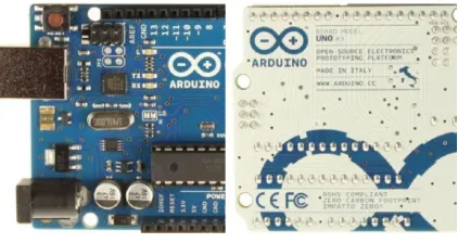
The Arduino Uno is a microcontroller board based on the ATmega328. It has 14 digital input/output pins (of which 6 can be used as PWM outputs), 6 analog inputs, a 16 MHz ceramic resonator, a USB connection, a power jack, an ICSP header, and a reset button. It contains everything needed to support the microcontroller; simply connect it to a computer with a USB cable or power it with an AC-to-DC adapter or battery to get started.
Figure 2: Arduino Uno Front and Back
The Uno differs from all preceding boards in that it does not use the FTDI USB-to-serial driver chip. Instead, it features the Atmega16U2 (Atmega8U2 up to version R2) programmed as a USB-to-serial converter.
The specifications of Arduino Uno are as follows:
Microcontroller ATmega328
Input Voltage (recommended) 7-12V
Input Voltage (limits) 6-20V
Digital I/O Pins 14 (of which 6 provide PWM output)
Analog Input Pins 6
DC Current per I/O Pin 40 mA
DC Current for 3.3V Pin 50 mA
Flash Memory 32 KB (ATmega328) of which 0.5 KB used by bootloader
SRAM 2 KB (ATmega328)
EEPROM 1 KB (ATmega328)
Clock Speed 16 MHz
A. Using PWM on an Arduino
Pulse Width Modulation or PWM is a technique for supplying electrical power to a load that has a relatively slow response. The supply signal consists of a train of voltages pulses such that the width of individual pulses controls the effective voltage level to the load. Both AC and DC signals can be simulated with PWM. The PWM pulse train acts like a DC signal when devices that receive the signal have an electromechanical response time that is slower than the frequency of the pulses. For a DC motor, the energy storage in the motor windings effectively smooth’s out the energy bursts delivered by the input pulses so that the motor experiences a lesser or greater electrical power input depending on the widths of the pulses. The formula below shows the voltage signal comprised of pulses of duration
0 that repeatevery
c units of time. The output of a PWM channel is either Vs volt during the pulse or zero volts otherwise. If thissignal is supplied as input to a device that has a response time much larger than
c, the device will experience the signal as an approximately DC input with an effective voltage ofc s
V
V
0eff
(1)The ratio
0 =
c is called the duty cycle of the square wave pulses. The effective DC voltage supplied to the load is controlled by adjusting the duty cycle. An Arduino Uno has 14 digital input/output (I/O) pins. Conventional, i.e., not PWM, operation of the digital I/O pins is controlled with the pinMode, digitalRead and digitalWrite functions. The pinMode function is used to configure a pin as an input or output. When a digital I/O pin is configured as an input, digitalRead reads the state of the pin, which will be either HIGH or LOW. In an Arduino sketch, HIGH is a predefined constant that is evaluated as “true" in a conditional expression, and is equivalent to a numerical value of 1. Electrically, a value of HIGH means the pin voltage is close to 5 V. Similarly, the constant LOW is interpreted as “false" in conditional expressions, it is numerically equivalent to 0, and electrically the pin voltage is 0. When a digital I/O pin is configured for output, digitalWrite is used to set the pin voltage to HIGH or LOW. On an Arduino Uno, PWM output is possible on digital I/O pins 3, 5, 6, 9, 10 and 11. On these pins the analogWrite function is used to set the duty cycle of a PWM pulse train that operates at approximately 500 Hz2. Thus, with a frequency fc = 500 Hz, the period is
c = 1/fc~2ms. As with conventional digital I/O, the pinMode function must be called first to configure the digital pin for output. The digital output voltage of an Arduino Uno is either 0 V or 5 V. Thus, in Equation (1), Vs = 5 V. The PWM
...
τo
τc
Vs
Figure 3: Variable width pulse train Equation (2) depicts the relationships between the PWM output parameters. Thus,
c
level
out
PWM
0255
_
_
(2)Therefore,
s eff
V
V
level
out
PWM
_
_
255
(3)Since Vs = 5V always, for routine calculations, we can use the simple formula
5
255
_
_
out
level
V
effPWM
B. LabVIEW Interface for Arduino (LIFA)
A sketch for the Arduino microcontroller acts as an I/O engine that interfaces with the LabVIEW Vis through a serial connection. This helps to move information from Arduino to LabVIEW without adjusting the communication, synchronization or even a single line of code. Using the Open, Read/Write, Close convention in LabVIEW we can access the digital, analog and pulse width modulated signals of the Arduino microcontroller. The Arduino microcontroller must be connected to the computer with the LabVIEW through a USB, Serial, or Bluetooth.
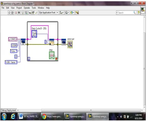
IV.RESULTS AND DISCUSSION A. Open-Loop System:
The Block Diagram of the Open-Loop System:
Figure 4: Block diagram of Open-Loop System
Front Panel of Open-Loop System:
Figure 5: Front Panel of the Open-Loop System
DC motor control using Pulse Width Modulation (PWM) signifies the controllability of the Arduino hardware and LabVIEW software. Graphical User Interface created by the LabVIEW is extremely pleasing and user friendly. Various controls like PID controllers, Analog and digital Filters etc can be incorporated in the advance versions in the closed loop system (PID block is available in LabVIEW control system palette) [2].
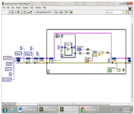
B. Closed-Loop System
The Block diagram of the Closed-Loop System is as shown below:
Figure 6: Block diagram of Closed-Loop System
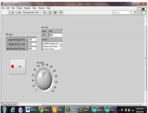
Front Panel of the Closed-Loop System:
Figure 7: Front Panel of Closed-Loop System
Duty cycle can be varied from 0-100% by varying the user controlled interactive graphical dial on the front panel. The response of the system can be changed by varying the gains of PID controller. These VI’s will be burnt in the Arduino microcontroller using LIFA_Base and interfaced with the dc motor. Setpoint, set by the user will be fed into the pid controller and passed on to the Arduino PWM pins. Arduino will pass those PWM pulses to the motor along with supply voltage that moves the motor. Shaft of the DC motor will move and number of times it moves will give us the speed at which the motor is moving. Tachometer is the sensor which measures the rotation will be used. Tachometer will be given external power supply voltage of 5V.
V. CONCLUSIONS
The method adopted in this paper is low cost technique of controlling the speed of the DC motor. Arduino Uno board plays the role of Data Acquisition System. DC motor is interfaced with PID Controller in LabVIEW via Arduino Uno board. Speed of the motor is sensed by the tachometer which is sent back to PID Controller as feedback for calculating and compensating the error produced if any. The method implemented can be used for various industrial applications. This technique helps in maintaining the stability of the system.
REFERENCES
1. M. Saranya, D. Pamela, “A Real Time IMC Tuned PID Controller for DC Motor", IJRTE ISSN: 2277-3878, Volume 1, Issue-1, April 2012 2. Naveen Kumar and Dr. Prasad Krishna, "Low cost data acquition and control using Arduino Prototyping platform and LabVIEW"
,IJSR,Volume 2, Issue-2, February 2013
3. Purna Chandra Rao et. al., “Robust Internal Model Control Strategy based PID Controller for BLDCM” ,International Journal of Engineering Science and Technology, Volume 2(11), 2010, 6801-6811.
4. Detchrat, et. al. , "IMC-Based PID Controllers Design for Two-Mass System", IMECS 2012 Volume - II, Hong Kong. 5. Ibrahim kaya, “IMC based automatic tuning method for PID controllers in a smith predictor configuration" , Sciencedirect, 2004
6. Farouk Zouari, et.al., “Ädaptive Internal Model Control of a DC Motor Drive System Using Dynamic Neural Network" Journal of Software Engineering and Applications, Scientific Research, 2012, 5, 168-189.