Intersection Cross Traffic Warning System for
Vehicle Collision Avoidance
Mohammed Ismail B. 1, Mohd.Abdul Muqeet 2, Mohammed Fawad Malik 3, Abdul Karim Khan 3
Senior Assistant Professor, Dept.of Electrical Engineering, Mufakham Jah College of Engineering &Technology,
Hyderabad, India 1
Associate Professor, Dept.of Electrical Engineering, MJCET, Hyderabad, India 2
B.E. Final Yr Student (E.I.E.), Dept.of Electrical Engineering, MJCET, Hyderabad, India 3
ABSTRACT: This paper facilitates the development and the implementation of an “Intersection Cross Traffic Warning System” (ICTWS) model for avoiding vehicle collision and prevents accidents at blind traffic intersection points. The developed system here uses a wireless communication system to warn collisions and alert the user of their respective vehicle while taking turns. The system uses Ultrasonic range finder sensors which detects the distance of the vehicles from the turning point and if the vehicle moves beyond the predefined limit then the system alerts it through indicator lights on the other side.
KEYWORDS: Intersection, Ultrasonic sensor, Tarang module, Inter-vehicle communication, Time of Flight
I. INTRODUCTION
Traffic Safety Systems are highway features designed primarily to reduce the severity of run-off-road collisions, prevent errant vehicles from crossing the median or decelerate errant vehicles. But these features are not limited to guardrail, crash cushions, median barrier, and end treatment, breakaway supports for signs and light standards, and truck escape ramps. According to a survey data source: “NMVCCS-2011-2013”, 36 % of all accidents occurs at intersection [5]. The main objective of this work is to design an effective Traffic Safety System at road intersections or street corners which is also economically viable & feasible for developing countries which have simple cost effective vehicles.
The project here is designed for advancing vehicle safety with the development of new crash avoidance systems that use wireless communications or an automatic signalling to detect and respond to imminent collisions. Recognizing the need of security of the human beings and vehicles, we have developed a system which can alert the user of the vehicle while taking turns. The system uses Ultrasonic range finder sensors which detects the distance of the vehicles from the turning point and when the vehicle moves beyond the predefined limit then the system alerts the it through indicator lights.
II. LITERATURE REIVEW
2. Wireless LAN Adapted Vehicles: These types of vehicles have various wireless technologies for communication such as using Ad Hoc Networking (VANET) over multiple wireless hops. These systems potentially develop a continuous network over the road lane through access points. Here, connected vehicles create a fundamental building block of “Intelligent Transport Systems” (ITS) and provides numerous application services to improve safety and comfort of driving [2] while also involving GSM & GPS Technologies. For vehicle-to-infrastructure communications, the system architecture assumes the access points with IEEE 802.11p network interfaces to be set up at least in dedicated locations (such as road intersections) [2]. But again this system is suited for a high infrastructure model and subsequently regular maintenance is required which is may not be possible for developing countries.
There are many other different systems designed for improving safety for commuters but unfortunately most of them are not really designed for busy roads, creating even worse traffic jams. This in turn results in neglecting the streets or highways with less density and dangerous intersections where commuters usually travel with high speeds un-cautioned.
Some automobile companies such as Audi have tried to develop inbuilt safety systems with sensor technologies that prevent car accidents but with the a very high price tag and moreover this system cannot be installed in already existing cars. The other systems for traffic safety include the GPS and GSM technologies but these have a major drawback of network coverage.
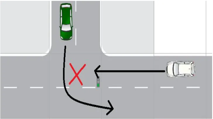
3. Proposed Inter Cross Section System: In this system, a simple cost effective Ultrasonic range finder sensor is used as a transmitter and receiver. Installing range detecting sensors at appropriate location & interfacing with a microcontroller can alert the vehicles on each side of intersection. The entire system is placed at the pole of the corner of any turning or intersection with two ultrasonic range finder sensors to their respective turning located phases. Compare to the above mentioned systems, the proposed warning system is cost-effective, suitable to all types of intersections & involves less infrastructure. Figure 1 shows an intersection where in the proposed ICWTS can be very helpful.
Figure 1: T-Intersection Where Chances Of Collision Are Very High
III. HARDWARE MODEL DESCRIPTION
The main aim of this work is to design traffic safety system in order to avoid the accidents at street corners. The major hardware components used in model are PIC 16F73 Microcontroller, Ultrasonic range finder SR-04, Tarang F4 Module (transmitter & receiver), Indicator LED’s, 230/12 Volt step down Transformer, 5 Volt RPS and 16x2 LCD unit.
device to another. This technique allows the short range of an individual node to be expanded and multiplied, covering a much larger area. PIC 16F73 Microcontroller is used as a controlling device programmed for time duration & vehicle detection interfaced with sensors & indicators. Whenever a person or vehicle appears at the one end of the street, the ultrasonic sensor detects the object and feeds that information to the microcontroller of same which will be transmitted to the another end microcontroller through Tarang modules displayed through their respective LEDs. LCD is used for maintenance & trouble shooting
.
IV. WORKING MODEL DESCRIPTION
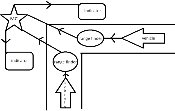
The Microcontroller will generate a 40 KHz transmission signal. The receiver module will receive this signal which is reflected from the surface of the object or any vehicle. The return signal is amplified & given to the microcontroller. The microcontroller is then used to calculate the time of flight (TOF) for the sound wave that is bounced off from distant objects or vehicles. Using this principle, a measure of distance is made and communicated to the other side indicator. The microcontroller here acts as a Central Controlling Unit communicating with the input and the output modules. Figure 2 shows the operational & installation diagram for a traffic cross section.
Figure 2: Operational diagrams of ICTWS for a traffic cross section
The entire system is placed at the pole of the corner of any turning with two ultrasonic range finder sensors to their respective turning located phases. Whenever the vehicle enters a turning location, the Ultrasonic sensor at the turning lane side of the pole gives the distance range of the vehicle presence and alerts if the vehicle crosses the set point threshold limit (1 to 4 meters can be extended). The system alerts the other side lane users through Red light indication to either reduce the speed or stop the second vehicle to avoid collisions. When there is no presence of the vehicle it indicates a green light for turning safely.
V. DESIGN DETAILS
Figure 3 Transmitter Circuit Figure 4 Receiver Circuit
After installing the sensors in appropriate location, range detection signal from each sensor is communicated through Tarang Module alerting the vehicles on each side of intersection using a microcontroller.
VI. EXPERIMENTAL SETUP
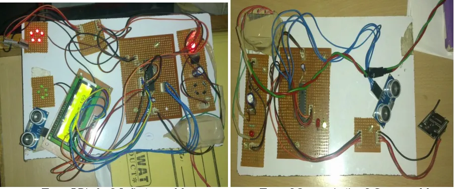
Figure 5 & 6 shows the hardware circuit with components which can be installed at the traffic cross section locations as shown in figure 2.
Figure 5 Display& Indicator module Figure 6 Communication & Sensor module
The project modules are shown in the pictures above. Figure 5 shows the display & indicator module whereas Figure 6 shows the communication & sensor module.
VII. RESULTS & DISCUSSIONS
Sl.No Distance (m) Time (s) Response (S)
1 1 3 20
2 1.5 4 18
3 2 5 16
4 2.5 6 14
5 3 7 12
6 4 8 10
Table 1: Readings of results
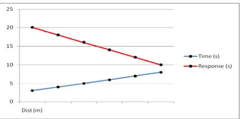
Figure 7: Graph indicating Response of Indicator
Table 1 indicates the results where Distance (m) is the distance of the vehicle from the sensor by which we can understand in which lane the vehicle is going. Time(s) is the time taken by the vehicle to cross the sensor by which we can calculate the speed of the vehicle. Response(S) is the time for which the RED indicator on the other side will be ON. The graph Figure 7 is plotted on the basis of readings taken at a T-intersection in a narrow lane of 20 feet. The results obtained have the following conditions:
1. If there is a vehicle only on one side of the intersection, then it does not have to stop or even slow down. 2. If there are vehicles on both the sides then depending upon their distances and speeds, the response time shall
be different & is indicated to the opposite side through LEDs on first come basis.
From the results we can see that , if the distance of the vehicle is more from the sensor it takes lesser time to cross the sensor (i.e. it is moving fast) , the response time (RED on other side) is less and vice versa .
VIII. CONCLUSION & FUTURE SCOPE
The developed ICTW system is installed & tested successfully for a “T Intersection”. Satisfactory results were obtained for a narrow lane of 20 feet. This system can also be installed for other types of intersections such as L & X-intersections. It can be very helpful in preventing traffic jams at narrow lanes connecting two streets or major roads and highways. This developed warning system can also avoid major accidents at dangerous intersections or blind curves. This system is cost effective, real time applicable for various environmental conditions & requires comparatively less maintenance.
Further this system can be improved with a message broadcast through GSM or GPS to their phone contacts that transiently communicate to emergency Services during an unlikely event of collisions.
ACKNOWLEDGEMENT
With a deep sense of gratitude, we thank Dr. M.P.Soni, Head of Electrical Engineering Department for permitting us to use Department Labs of Microprocessor & Microcontroller and Integrated Circuits which aided in the successful completion of this work. We would also like to convey our regards and thanks to Dr. Basheer Ahmed , Director-cum-Advisor, Dr. Ashfaque Jafari Dean (Academics) Muffakham Jah College of Engineering & Technology, Hyderabad for their constant encouragement & support. We are also grateful to all Teaching & non-teaching Faculty of EED for their cooperation and sagacious guidance at every stage of this work and contributing for its success.
REFERENCES
[1] Tarik Taleb, Abderrahim Benslimane and Khaled Ben Letaief, Toward Effective Risk-Conscious and Collaborative Vehicular Collision Avoidance System IEEE TRANSACTIONS ON VEHICULAR TECHNOLOGY, VOL. 59, NO. 3, pp 1474-1485 MARCH 2010 [2] Andreas Festag, Alban Hessler, Roberto Baldessari “vehicle-to-vehicle and road-side sensor communication for enhanced road safety” January
2009.
pp. 2212–2217 Mar. 2008
[4] Gildas Lefaix, Eric Merchand, Patrick Bouthemy Motion-based Obstacle Detection and Tracking for Car Driving Assistance IAPR International Conference on Pattern Detection, Canada 2010 January.