Design and Implementation of an 11-Level
Inverter with FACTS capability for Energy
Distributed Systems
K.Vijaya Bhaskar1, Lekkala Balaji2
Assistant Professor, Dept. of EEE, SVPCET, Puttur, Andhra Pradesh, India1
PG Student [EPS], Dept. of EEE, SVPCET, Puttur, Andhra Pradesh, India2
ABSTRACT: In this paper, a new single-phase wind energy inverter (WEI) with flexible AC transmission system (FACTS) capability is presented. The proposed inverter is placed between the wind turbine and the grid, same as a regular WEI, and is able to regulate active and reactive power transferred to the grid. This inverter is equipped with distribution static synchronous compensators option in order to control the power factor (PF) of the local feeder lines. Using the proposed inverter for small-to-medium-size wind applications will eliminate the use of capacitor banks as well as FACTS devices to control the PF of the distribution lines. The goal of this paper is to introduce new ways to increase the penetration of renewable energy systems into the distribution systems. This will encourage the utilities and customers to act not only as a consumer, but also as a supplier of energy. Moreover, using the new types of converters with FACTS capabilities will significantly reduce the total cost of the renewable energy application. In this paper, modular multilevel converter is used as the desired topology to meet all the requirements of a single-phase system such as compatibility with IEEE standards, total harmonic distortion (THD), efficiency, and total cost of the system. The proposed control strategy regulates the active and reactive power using power angle and modulation index, respectively. The function of the proposed inverter is to transfer active power to the grid as well as keeping the PF of the local power lines constant at a target PF regardless of the incoming active power from the wind turbine. The simulations for an 11-level inverter have been done in MATLAB/Simulink. To validate the simulation results, a scaled prototype model of the proposed inverter has been built and tested
KEYWORDS: Modular multilevel converter (MMC),multilevel inverter (MLI), wind energy inverter (WEI).
I.INTRODUCTION
The Roleof power electronics in distribution systems has greatly increased recently. The power electronic devices are usually used to convert the nonconventional forms of energy to the suitable energy for power grids, in terms of voltage and frequency. In permanent magnet (PM) wind applications, a back-to-back converter is normally utilized to connect the generator to the grid. A rectifier equipped with a maximum power point tracker (MPPT), converts the output power of the wind turbine to a dc power. The dc power is then converted to the desired recent developments in wind energy, utilizing smarter wind energy inverters (WEIs) has become an important issue. There are a lot of single-phase lines in the United States, which power small farms or remote houses [1], [2]. Such customers have the potential to produce their required energy using a small-to-medium-size wind turbine. Increasing the number of small-to-medium wind turbines will make several troubles for local utilities such as harmonics or power factor (PF) issues.
generation systems as well as the power systems to operate as a source or sink of reactive power to increase the power quality issues of the power lines. Using regular STATCOMs for small-to-medium-size single-phase wind applications does not make economic sense and increase the cost of the system significantly. This is where the idea of using smarter WEIs with FACTS capabilities shows itself as a new idea to meet the targets of being cost-effective as well as compatible with IEEE standards. The proposed inverter in this paper is equipped with a D-STATCOM option to regulate the reactive power of the local distribution lines and can be placed between the wind turbine and the grid, same as a regular WEI without any additional cost. The function of the proposed inverter is not only to convert dc power coming from dc link to a suitable ac power for the main grid, but also to fix the PF of the local grid at a target PF by injecting enough reactive power to the grid. In the proposed control strategy, the concepts of the inverter and the D-STATCOM have been combined to make a new inverter, which possesses FACTS capability with no additional cost. The proposed control strategy allows the inverter to act as an inverter with D-STATCOM option when there is enough wind to produce active power, and to act as a D-STATCOM when there is no wind. The active power is controlled by adjusting
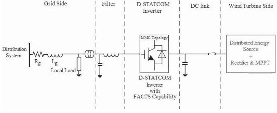
Fig. 1. Complete configuration of the proposed inverter with FACTS capability.
the power angle δ, which is the angle between the voltages of the inverter and the grid, and reactive power is regulated by the modulation index m.There are a large number of publications on integration of renewable energy systems into power systems. A list of com-plete publications on FACTS applications for grid integration of wind and solar energy was presented in [3]. In [4], new commercial wind energy converters with FACTS capabilities are introduced without any detailed information regarding the efficiency or the topology used for the converters. In [5], a complete list of the most important multilevel inverters was reviewed. Also, different modulation methods such as sinusoidal pulsewidth modulation (PWM), selective harmonic elimination, optimized harmonic stepped waveform tech-nique, and space vector modulation were discussed and com-pared. Among all multilevel topologies [6]–[9], the cascaded H-bridge multilevel converter is very well known for STATCOM applications for several reasons [10]–[12].
current-source inverter, which controls reactive power and regulates voltage at the point of common coupling (PCC). Varma et al. [19], [20] propose an application of photovoltaic (PV) solar inverter as STATCOM in order to regulate voltage on three-phase power systems, for improving transient stability and power transfer limit in transmission systems. The authors called their proposed system PV-STATCOM. Similar to wind farms (when there is no wind), solar farms are idle during nights. We proposed a control strategy that makes the solar farms to act as STATCOMs during night when they are not able to produce active power. The main purpose of the PV-STATCOM system is to improve the voltage control and the PF correction on three-phase transmission systems.
In this paper, the proposed WEI utilizes MMC topology, which has been introduced recently for HVDC applications. Replacing conventional inverters with this inverter will elimi-nate the need to use a separate capacitor bank or a STATCOM device to fix the PF of the local distribution grids. Obviously, depending on the size of the power system, multiple inverters might be used in order to reach the desired PF. The unique work in this paper is the use of MMC topology for a single-phase voltage-source inverter, which meets the IEEE standard 519 requirements, and is able to control the PF of the grid regardless of the wind speed Fig. 1 shows the complete grid-connected mode configuration of the proposed inverter. The dc link of the inverter is connected to the wind turbine through a rectifier using MPPT and its output terminal is connected to the utility grid through a series-connected second-order filter and a distribution transformer.
II.MODULAR MULTILEVEL CONVERTER
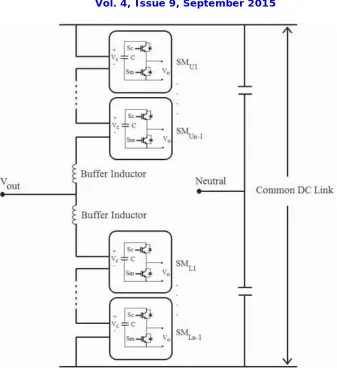
MMC has gained increasing attention recently. A number of papers were published on the structure, control, and applica-tion of this topology [21], [22], but none has suggested the use of that for inverter + D-STATCOM application. This topology consists of several half-bridge (HB) submodules (SMs) per each phase, which are connected in series. An n-level single-phase MMC consists of a series connection of 2(n− 1) basic SMs and two buffer inductors. Each SM possesses two semiconductor switches, which operate in complementary mode, and one capacitor. The exclusive structure of MMC becomes it an ideal candidate for medium-to-high-voltage applications such as wind energy applications. Moreover, this topology needs only one dc source, which is a key point for wind applications. MMC requires large capacitors which may increase the cost of the systems; however, this problem is offset by the lack of need for any snubber circuit.
The main benefits of the MMC topology are: modular design based on identical converter cells, simple voltage scaling by a series connection of cells, simple realization of redundancy, and possibility of a common dc bus. Fig. 2 shows the circuit configuration of a single-phase MMC and the structure of its SMs consisting of two power switches and a floating capacitor.
The output voltage of each SM (vo) is either equal to its capacitor voltage (vc) or zero, depending on the switching states. The buffer inductors must provide current control in each phase arm and limit the fault currents. To describe the operation of MMC, each SM can be considered as a two-pole switch. If Sui, which is defined as the status of the i th submodule in the upper arm, is equal to unity, then theoutput of the ith SM is equal to the corresponding capacitor voltage; otherwise it is zero. Likewise, if Sli which is defined as the status of the i th submodule in the lower arm, is equal to unity, then the output of the i th lower SM is equal to the corresponding capacitor voltage; otherwise it is zero. Generally, when Sui or Sli is equal to unity, the i th upper or lower SM is ON; otherwise it is OFF. Therefore, the upper and
lower arm voltages of the MMC are as follows:
v
upperArm =
n−1
(Suivci) +v11(1)
i =1
v
lowerArm =
n−1
Fig. 2. Structure of a single-phase MMC inverter structure.
where v11 and v12 are the voltages of the upper and lower buffer inductors, n is the number of voltage levels, and vci is the voltage of the i th SMs capacitor in upper arm or lower arm. A single-phase 11-level MMC inverter consists of 20 SMs which translates to 40 power switches, 20 capacitors, and 2 buffer inductors. The dc and ac voltages of the 11-level MMC are described by
v
DC =
v
upperArm +v
lowerArm= 10
(Suivci) +
10
i =1
(Suivci) + (v11+v12) (3)
i =1
v
out = vDC−
v
upperArm = − vDC+
v
lowerArm. (4)
III. PROPOSED CONTROL STRATEGY
distributive control of volt-ampere reactive(VAR) compensation and PF correction of feeder lines.The application of the proposed inverter requires active and reactive power to be controlled fully independent,so that if wind is blowing,the device should be working as a normal inverter plus being able to fix the PF of the grid at a target PF- (D-STATCOM option),and if thre is no wind ,the device should be only operating as a D-STATCOM(or capacitor- bank) to regulate PF of the local grid. This translates to two modes of operation.when wind blowing and active power is coming from wind turbine:the inverter plus D-STATCOM mode. In this mode,the device is working as a regular inverter to transfer active power from the renewable energy source to the grid as well as working as a normal D-STATCOM to regulate the reactive power of the grid in order to control the PF of the grid and 2) when wind speed is zero or too low generate active power : the D-STATCOM mode . In this case,the inverter is acting only as a source of reactive power to control the PF of the grid,as a D-STATCOM. This option eliminates the use of additional capacitor banks or external STATCOMs to regulate the PF of the distribution feeder lines. Obviously, the device is capable of outputting up to to its rated maximum real power and/or reactive power ,and will always output all real power generated by the wind turbine to the grid . The amount of reactive power ,up to the design maximum,is dependent only on what the utility asks the device to produce
Fig. 3. Schematic of the proposed controller system.
Generally ,(5) and (6) dictate the power flow between a – STATCOM device and power lines
E S E L
PS= − X sin δ
E S E L cosδ− E L2
Q S= − X
Where x is the inducatance between the STATCOM (here as inverter) and the grid which is normally considered as output filter inductance . The root mean square (RMS) voltage of the STATCOM is given as Es and is considered to be out of phase by an angle of RMS line voltage E1. In the proposed control strategy ,active and reactive power transferred between the inverter and the distribution grid is controlled by selecting both the voltage level of the inverter and grid, respectively. The amplitude of the inverter voltage is regulated by changing the modulation index m and the angle by adding a delay to the firing signals which includes
PS= −
m E S E L sin δ X 2 Q
S= −
m E S E Lcosδ− E L
X
Using (9) and (10), the target reactive power for the grid is determined and is compared with the actual value of the reac-tive power of the grid. Using a PI compensator will determine the desired value for the modulation index. The power angle is also determined by comparing the actual dc voltage of the inverter with a reference value.
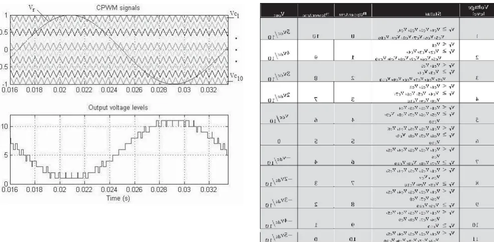
A PI compensator determines the desired value for the power angle.The second function of the controller systems is to keep the capacitors’ voltages balanced. In order to do this, a carrier-based pulsewidth modulation (CPWM) method [25], [26] is used. The top graph in Fig. 4 shows the reference signal and the carrier waveforms for an 11-level MMC inverter using CPWM technique. The bottom graph of Fig. 4 shows the output voltage levels generated based on Table I.
In an 11-level CPWM technique, ten carrier signals are compared with a reference sinusoidal signal. In Fig 4, based on the phase of the reference signal (vr), there are 11 operating regions where each region defines a voltage level in the
output
n
upperArm + nlowerArm = 10 (11)
where nupperArm and nlowerArm are the numbers of SMs which are ON (Sc is ON and Sm is OFF in Fig. 1) in the upper arm
or lower arm, respectively.
In an 11-level MMC inverter, there are ten upper and ten lower SMs where each SM has a capacitor. For instance, in voltage level 1 of Table I, all the upper SMs should be OFF and all the lower SMs should be ON, which translates to the fact. In an 11-level MMC inverter, there are ten upper and ten lower SMs where each SM has a capacitor. For instance, in voltage level 1 of Table I, all the upper SMs should be OFF and all the lower SMs should be ON, which translates to the fact that the main switches Sm of all upper SMs and the auxiliary switches (Sc) of all lower SMs have
to be ON and all the other switches have to be OFF. In this case, the input dc voltage is applied only to the ten lower capacitors, so that the output voltage is vDC/2. Fig. 5 illustrates the selection of capacitors for different voltage levels shown in Table I.
lowest voltages are selected, respectively. As a result, ten capacitors with lowest voltages are chosen to be charged.
Likewise, if the current flowing through the switches is negative, so that capacitors are being discharged, nupperArm and
nupperArm of the SMs in upper arm and lower arm with highest voltages are selected, respectively. As a result, ten capacitors with highest voltages are chosen to be dis-charged. Consequently, the voltages of the SMs’ capaci-tors are balanced. Considering Table I and based on the direction of the current flowing through the switches, the proper algorithm will be selected to maintain capacitor balance.
The third function of the controller system is the PWM generation block. In this block, based on the desired modulation index, power angle, voltages of the capacitors, direction of the current flowing through the switches and using Table I, the controller generates the PWM signals in order to meet all the system requirements.
IV. SIMULATION AND PRACTICAL RESULTS
The design of an 11-level MMC inverter was carried out in MATLAB/Simulink. The simulation is 20 s long and contains severe ramping and de-ramping of the wind turbine. The goal is to assess the behavior of the control system in the worst conditions. Table II shows the values of the parameters used for the simulation.
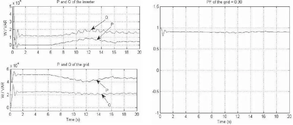
Before t = 6 s, there is no wind to power the wind turbine; therefore, the dc link is open-circuited. At t = 6 s, the input power of the inverter is ramped up to 12 kW in 5 s, and then ramped down to 3.5 kW 4 s later. Fig. 6 shows the output active power from the wind turbine. In the simulation, the local load makes the PF 0.82. When the simulation starts, the inverter provides enough compensation to reach the target PF 0.90. Fig. 7 shows the output active and reactive power from the wind turbine and the grid. After t = 6 s, the output power of the wind turbine is increased, and as a result the level of active power provided by the feeder line is decreased by the same amount.
The simulated output voltage of the inverter before the filter is shown in Fig. 8. Fig. 9 shows the PF of the grid. The PF of the grid is constant at 0.90 regardless of the active power from the wind turbine, showing that the main goal of the inverter is achieved. The set-point for dc link voltage of the inverter is 2000 V and the RMS value of the output ac voltage is 600 V.
The delta and modulation index graphs are shown in Fig. 10. As soon as the active power comes from the wind turbine, the controller system increases the value of the power angle in order to output more active power to the grid.
Therefore, the active power provided from the feeder lines to the load is decreased, and as a result the reactive power from the feeder lines is decreased. Consequently, the modulation index is increased by the controller system to inject more reactive power needed by the load.
.
To validate the simulation results, a scaled version of the proposed inverter has been built and tested. The power rating of the scaled prototype model is 250 W and/or VAR, which is limited by the rating of the semiconductor devices. The experimental results serve only as a proof-of-concept. In order to implement the control strategy and to handle the feedback signals, two CLP 1104 dSPACE systems have been synchro-nized. A three-phase PM generator driven by a variable speed dc motor is used to emulate the wind speed change. Fig. 11 shows the test bench setup and the 11-level prototype inverter.
Fig. 12 shows the output voltage of the inverter where the switching frequency and the values of the LC filter is 2 kHz, 5 mH, and 10 μF, respectively. The efficiency of the inverter is close to 0.95. The experimental output voltage THD and current TDD is 2.7 and 2.12%, respectively.
In grid-connected mode, the inverter is connected to the grid through a transformer with the ratio 120:24. The load PF is set to 0.65 and the target PF is 0.90. In this case, the job of the inverter is to fix the PF at the target PF regardless of the input active power from the wind emulator.
In order to show the performance of the system conveniently, an AEMC 8230 power meter is used and the practical results are captured and shown using and the ControlDesk, which is a helpful tool associated with the dSPACE 1104 package. Fig. 13 shows the system parameters before compensation in which the inverter is disconnected from the grid. In this case the inverter is open-circuited and there is no active or reactive power transfer between the inverter and the wind emulator.
Fig. 7. Simulated active and reactive power of the inverter (top
graph), active Fig. 8. Simulated PF of the
V. RESULT AND DISCUSSION
Fig.9.Simulated output voltage of an 11-Level Inverter Fig.10.Simulated and delta and modulation index of the
11-level inverter
VI.CONCLUSION
In this paper, the concept of a new multilevel inverter with FACTS capability for small-to-mid-size wind installations is presented. The proposed system demonstrates the application of a new inverter with FACTS capability in a single unit without any additional cost. Replacing the traditional renew-able energy inverters with the proposed inverter will eliminate the need of any external STATCOM devices to regulate the PF of the grid. Clearly, depending on the size of the compensation, multiple inverters may be needed to reach the desired PF.
This shows a new way in which distributed renewable sources can be used to provide control and support in distribution systems. The proposed controller system adjusts the active power by changing the power angle (delta) and the reactive power is controllable by the modulation index m. The simulation results for an 11-level inverter are presented in MATLAB/Simulink. To validate the simulation results, a scaled prototype of the proposed 11-level inverter with D-STATCOM capability is built and tested. Practical results show good performance of the proposed control strategy even in severe conditions.
REFERENCES
1. U.S. Solar Market Insight, 2010 Year End Review Executive Summary,SEIA, Washington, DC, USA, 2011. 2. AWEA U.S. Wind Industry Annual Market Report Year Ending 2010,AWEA, Washington, DC, USA, 2011.
3. S. A. Rahman, R. K. Varma, and W. H. Litzenberger, “Bibliography of FACTS applications for grid integration of wind and PV solar power systems: 1995–2010 IEEE working group report,” in Proc. IEEE PowerEnergy Soc. General Meeting, Jul. 2011, pp. 1–17.
A. Beekmann, J. Marques, E. Quitmann, and S. Wachtel, “Wind energy converters with FACTS capabilities for optimized integration of wind power into transmission and distribution systems,” in Proc. CIGRE/IEEE PES Joint Symp. Integr. Wide, Scale Renew. Resour. Power Del. Syst.,Jul. 2009, pp. 1–9.
4. J. Rodriguez, J. S. Lai, and F. Z. Peng, “Multilevel inverters: Survey of topologies, controls, and applications,” IEEE Trans. Ind. Appl., vol. 49, no. 4, pp. 724–738, Aug. 2002.
5. F. Z. Peng, J. S. Lai, J. W. McKeever, and J. VanCoevering, “A mul-tilevel voltage-source inverter with separate DC sources for static VAr generation,” IEEE Trans. Ind. Appl., vol. 32, no. 5, pp. 1130–1138, Oct. 1996.
6. L. M. Tolbert and F. Z. Peng, “Multilevel converters as a utility interface for renewable energy systems,” in Proc. IEEE Power Eng. Soc. SummerMeeting, vol. 2. Jul. 2000, pp. 1271–1274.
8. [9] C. Tareila, P. Sotoodeh, and R. D. Miller, “Design and control of a single-phase D-STATCOM inverter for wind application,” in Proc. PEMWA, Jul. 2012, pp. 1–5.
9. B. Gultekin and M. Ermis, “Cascaded multilevel converter-based trans-mission STATCOM: System design methodology and development of a 12 kV ±12 MVAr power stage,” IEEE Trans. Power Electron., vol. 28, no. 11, pp. 4930–4950, Nov. 2013.
10. K. Sano and M. Takasaki, “A transformerless D-STATCOM based on a multivoltage cascade converter requiring no DC sources,”
11. IEEE Trans. Power Electron., vol. 27, no. 6, pp. 2783–2795, Jun. 2012.
12. X. Liang, Y. Xu, X. Chen, and C. Guo, “The simulation research of STATCOM based on cascaded multi-level converter,” in Proc. 4th Int. Conf. Electr. Util. DRPT, Jul. 2011, pp. 494–498.
13. M. Davies, M. Dommaschk, J. Dorn, J. Lang, D. Retzmann, and D. Soerangr, HVDC PLUS Basic and Principle of Operation. Erlandgen, Germany: Siemens AG Energy Sector, 2009.
14. B. Gemmell, J. Dorn, D. Retzmann, and D. Soerangr, “Prospects of multilevel VSC technologies for power transmission,” in Proc. IEEE Transmiss. Distrib. Conf. Exposit., Apr. 2008, pp. 1–16.