Wireless Controlling of Electrical Lighting
Systems through Digital Signal to Reduce the
Complexity in the Electrical Network
MT Thahir1, Mahesh Edirisinghe2, YHN Dilhani3PG Student, Faculty of Science, University of Colombo, Colombo 03, Sri Lanka1
Senior Lecturer, Faculty of Science, University of Colombo, Colombo 03, Sri Lanka2
UG Student, Faculty of Science, University of Colombo, Colombo 03, Sri Lanka3
ABSTRACT: The innovative approach of wireless controlling in electrical lighting systems through electrical digital
signal is presented in this study, which can be used to replace the wired wall switches in order to reduce the complexity in the electrical network while enhancing the operational safety. Importantly, the system would facilitate to communicate very effectively without any interference between devices, when more wireless control devices used in large electrical systems in industries and it introduces two way communication for status indication. The developed system consist of a PIC18F452 Microcontroller Unit, a RF Module, a Switch Unit, a Relay Unit, an AC Current Sensing Circuit, a Voltage Regulator and a Power Supply Unit. The central process of constructing the system was designing and implementing the Switch Unit and the Relay Unit to control the electrical load connected to the Relay Unit. The developed system operates on XBee networking protocol IEEE 802.15.4 and functions within the ISM 2.4 GHz frequency band and are pin-for-pin compatible with each other whereas the effective outdoor distance range is radially outward of 70 m. Moreover, specific advantages and conveniency of using the developed system over conventional wired network is also been discussed.
KEYWORDS: Wireless electrical network, Wiring complexity, RF network, ISM band network.
I.INTRODUCTION
Nowadays most of technological and industrial sectors are focused on introducing low cost, minimal power consuming and long lasting data communication systems to deploy in modern industries and often endeavour to find solutions for difficulties and failures which may arouse in traditional wire connecting systems and perhaps even with existing large scale wireless systems [1]. Gradually, wireless technology has been risen swiftly for monitoring and controlling of various processes in industrial and other applications with vast potential of advance in technology. Therefore, currently, this technology governs a wide role with the intention of diminishing the drawbacks of existing complicated wired systems which has been used for monitoring and controlling of processes over decades.
As a common fact, in industrial and commercial lighting systems have very complicated cable laying and the wire connections throughout the premises cost huge amount of money, time and effort. In contrasting that, using the RF wireless modules to communicate between devices in premises, no complex wire connections are required.So far, many researches have been conducted and some novel researches are undergoing in order to improve and enhance the feasibility of wireless systems in numerous areas [2]. Typically, it has been investigated to be used in industrial environment to automate and to diminish the man power while making the process more rapid and more productive [2-4]. Nevertheless as mentioned and discussed in [5], there is a consequence that the wireless systems are operated by storage batteries which require longer lifetimes and the consequences of expanding this technology on various industries are investigating on many research areas.
other side and it could be crucial when remote controlling. Moreover, in most of wireless controlling, they seems only being focused on one way communication which is similar situation as reported in [6] and henceforth there are only limited number of researches have been conducted up to now. As an elucidation, one of the main objective of this study is to introduce two way communication system to operate distant circuit while avoiding existing drawbacks and presenting innovative model to enhance the effectiveness.
Moreover, using radio frequency (RF), it enables to control distance objects using a variety of radio signals transmitted by a corresponding remote control device. Furthermore, using RF control system, it can control a variety of mechanical or electronic devices to complete various switching operations. As a complementary method to IR remote control type, the RF remote control is widely used in operative functions at home garages, electric gates, automatic barriers, industrial applications, wireless burglar alarm systems and etc.
Typically, electrical lighting systems in industrial, residential, commercial places and street lamps are monitored and controlled by conventional wired system, which may not efficient in terms of cost and maintenance. In contrasting, in wireless technology introduces a more sophisticated, economical and reliable wireless switching systems with risk preventive actions for the benefits of consumers. The proposed Wireless Controlling of Electrical Lighting System through digital signal (WiCELS) would adopt to overcome this issues. Even though wireless technology has many advantages over conventional systems, WiCELS is not widely available for controlling electrical industrial and commercial lighting systems in Sri Lankan context at the present.
In this study it was expected to improve currently existing wireless control system to indicate the status on the receiving end, enabling for more precise and fault free functioning. Moreover, it is expected to introduce two way communication system using RF controlling to designate the status of the receiving end while diminishing the malfunctions which may occur due to less awareness of the condition at the other end, which may lead to monitor and control the processes more accurately and precisely without any interference between devices. The WiCELS module introduced in this study, is expected to introduce an unique feature to indicate the real status of the RX via LED indicator in the TX unit to display whether the lamp is really lit up or not for visually make sure even from some distance. With the purpose of that, an innovative prototype model has been designed and its importance has been discussed in this paper by illustrating the above mentioned process. While improving unique advantages of existing devices, some further drawbacks from other related products have been eliminated through WiCELS technology. Moreover, this module also would facilitate to communicate very effectively without any interference between devices when more wireless control devices used in a large electrical system in industries.
A single lamp Relay Unit and its corresponding Switch Unit is illustrated in Fig 1 which provides an overview of the proposed WiCELS module. As can be seen there, a four byte length code is used as a device identification with one byte length code for Relay Unit identification which will make secure controlling and prevent interference whereas status display LEDs indicate the lamp status whether it is really in operation or not.
Fig. 1: Overview of the proposed WiCELS module for single lamp control.
II.DESIGN METHODOLOGY
In order to contrast the main objective of the research, it was determined to design a prototype model which is operating by means of wireless control technology. The WiCELS module utilized in this prototype model is consisting of a PIC18F452 Microcontroller Unit, RF Module, an Switch Unit, a Relay Unit, an AC Current Sensing Circuit, a
With the intention of communicating between the Switch Unit and the Relay Unit, XBee protocol has been equipped. It is essential to interact between these two units by means of RF Module as an essential requirement of the proposed system. As stated in [7], the XBee RF Module was engineered to meet IEEE 802.15.4 standards and support the unique needs of low-cost, low-power wireless sensor networks and provide reliable delivery of data between devices. The modules operate within the ISM 2.4 GHz frequency band and are pin-for-pin compatible with each other.
Despite the fact that in a single XBee unit, there could be implemented up to 8 switches and 8 LEDs in order to indicate the prominence of the bulbs, only 4 switches and 4 LEDs are comprised in the prototype by the means of convenience, though it could be extend to any extent as required when it comes to the real world application. The Switch Unit
comprises of PIC18F452 CMOS FLASH based 8-bit microcontroller, six operating switches, four LEDs, and a RF Module transceiver whereas the Relay Unitalso contains a PIC18F452, four lamps as the load and a RF Module Transceiver. All connections of the wireless control of lighting systems have been made according to the functional block diagram as shown in Fig 2 whereas Fig 2(a) and Fig 2(b) show the Switch Unitand Relay Unit respectively.
Fig. 2: Functional block diagram of the WiCELS Module (a) Switch Unit; (b) Relay Unit.
It is important to have an overlook of the operation procedure of the WiCELS which has been used in this study. For the purpose of controlling the lamps, in the Switch Unit there has been used four switches to ON/OFF individually and additional two switches to ON/OFF all lamps at the same time as indicated in Fig 2(a). The schematic diagram of the
Switch Unit is shown in Fig 3. If one of the six switches is pressed, the particular pin which is connected to the switch of the PIC microcontroller gets logic 1, then it loads corresponding four byte Device ID and one byte Relay ID serially and send it as an encoded signal from TX pin of microcontroller to the RF Module in the Switch Unit.
As soon as a push button (SW1-SW6) in the Switch Unit is pressed, the PIC will send a unique encoded code according to its input (as per the relevant switch pressed) to the receiver of the Relay Unitthrough the transmitter of the Switch Unit. The signal from the Switch Unit will be transmitted in the form of RF to the Relay Unit. The receiver of the Relay Unitwill accept the signal and match the signal with the DeviceID, it is ok then match the Lamp ID and send it to the corresponding transistor and to the relevant LED which would indicate that which relay is in operate. When the Relay Unit receives the signal, it will be processed at the PIC microcontroller. The Relay Unit will be received the voltage signal corresponding to the signal which is being processed by the microcontroller and transmitted from the Switch Unit via RF Module. The schematic diagram of the Relay Unitis shown in Fig 4. At the processing, initially corresponding four byte Device ID signal will be compared with its programmed Device ID serially and if it is acceptable then the received one byte Relay ID signal will be compared. Thus the particular Relay Switch will be energized according to the signal processed. The AC Current Sensing Circuit indicated in Fig 5 which is coupled to the
Relay Unit detects the current through the particular lamp. As shown in Fig 5, there is an AC Current Sensing Unit for each lamp in order to identify the particular lamp to be lit ON or OFF when current is flowing through it by using optocouplers.
Fig. 4: Schematic diagram of the Relay Unit.
Once the feedback to the microcontroller and the signal of the detection will be transmitted to the Switch Unit, it enables to energize the particular LED as a status display of the lamp hence, status of the lamps can be identified. The microcontroller in WiCELS is PIC18F452 which is programmed by using C language with MikroC PRO 2010 compiler and the software development process for the Switch Unit and the Relay Unit can be summarized using a flow chart as shown in Fig 6.
Fig. 6: Flow chart of the software development (a) Switch Unit; (b) Relay Unit.
III. IMPLEMENTATION AND VALIDATION
With the completion of programming process and hardware construction, the prototype module had to undergo testing stage in order to ensure that the overall system is well functions throughout the overall process. Initially, test was carried out to make sure that the critical voltages supply by the Power Supply Unit are satisfactory to operate PICs, RF Modules and other electrical components. Hence, the Power Supply Unit was tested and a voltage of 12 V was obtained. Subsequently, the regulator which was used in both Switch Unit and Relay Unit was subjected to test. In this case a DC voltage of 3.3 V was read ensuring that the microcontroller and the RF Module were received enough power for its operation. A photograph taken during the testing of the power supply unit is shown in Fig 7(a) whereas Fig 7(b) shows a photograph taken during the testing of the regulator circuit which shows 3.178 V after fully loaded.
Fig. 7: Photograph taken during the testing of (a) Power Supply Unit; (b) Regulator Circuit.
Unitin order to indicate the status of lamp by glowing its particular LED. Once this circuit is connected to the power supply, the red and green LEDs will lit ON for a few second designating that the circuit has a supply and has no malfunction in terms of connectivity and the microcontroller is ready for its operation.
Fig. 8: Photograph taken during the testing (a) Relay Unit circuit; (b) Switch Unit circuit.
Furthermore, the output signal of the Switch Unit is tested at its USART terminal and for the Relay Unit it was tested at its RF module by keeping the distance of one meter away from the Switch Unit. Captured waveforms of five byte signal generated (4 byte Device ID signal + 1 byte Relay ID signal) for the Switch Unit and the Relay Unit are pictured in Fig 9(a) and Fig 9(b) respectively.
Fig. 9: Recorded output signal (a) Switch Unit: USART pin; (b) Relay Unit: RF Module.
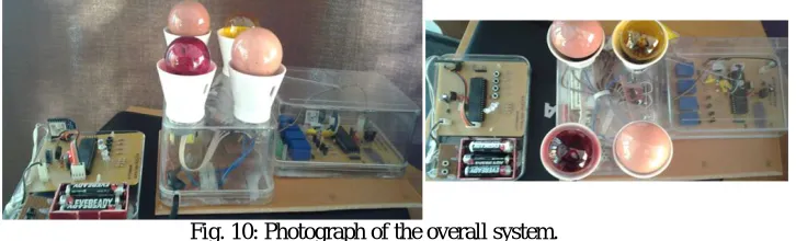
After the completion of the construction of the proposed system, a series of test procedures was essential to carry out in order to assure that the developed system is functioning fault free without interfering and accurately, whereas Fig 10 shows the pictorial overview of the prototype constructed consist of a Microcontroller Unit, a RF Module, an Switch Unit, a Relay Unit, an AC Current Sensing Circuit, a Voltage Regulator, and a Power Supply Unit.
Fig. 10: Photograph of the overall system.
Meanwhile, another test was carried out in order to find the effect of line-of-sight. For that, the Switch Unit height was changed from the ground level up to 3 m and for every variation of 0.5 m height, the Relay Unit height was kept at ground level and its response was observed by changing the separation distance up to 100 m by following the same increment distance as mentioned above. The line-of-sight testing procedure was further extended by changing the Relay Unitheight from ground level up to 3 m with a variation of 0.5 m height with respect to ground. According to the results obtained, it is apparent that the overall results for all the angles measured remain unaltered regardless of the position of the two units up to 90 m which is the specified range for RF Unit by the manufacturer [7]. Furthermore, in order to find the response under rainy weather condition, foresaid experiment was repeated by creating artificial water spray channel and the effective response distance was found to be maximum of 70 m. However, by recalling the manufactures specifications as mentioned in [7], the effective operation distance may reduce down to 30 m if the developed WiCELS
unit is used in an indoor or an urban environment. Therefore, in here it works as omi-directional transceiver system and it can be concluded that the line-of-sight alignment is not required which can be considered as an added advantage.
IV. DISCUSSION
The aim of this project is to develop a wireless control of electrical lighting systems through electrical digital signal (WiCELS) that enables to control electrical lamps/power outlets without return wires. Further, it mainly focused on practical purposes which may useful for even household electrical systems something that can be related on a daily basis whereas the developed system does not required a physical interface between the RF Module used and the microcontroller. In here, the system hardware has been successfully built with the expected functionality and it was thoroughly tested and now is ready for commercialization. The innovative approach of WiCELS is to reduce the complexity in the electrical network which is the expected outcome of this project which will replace the conventional wired wall switches.
When it comes to practical applications, it is highly recommend to use developed WiCELS in electrical lighting systems, so that it will facilitate to reduce the complexity of the wired network while enhancing the operational safety where the system will be isolated from live wiring. Furthermore, it requires less installation time with a convenient installation process, undeniably less maintenance once implemented together with having an advantage of status indicators. Hence there is no requirement of routine physical checking which would reduce the labour cost as well. It is important to mention that no line-of-sight alignment is necessarily required for the functionality of the system and four byte Device ID and one byte Relay ID provide to have a secure communications with no interferences possible even within different WiCELS units.
Furthermore, it is important to mention here that using the developed system, it would enable to reach out for certain areas remotely which would be more hazardous or considerably difficult to reach out by a human being without causing any damages. Moreover, effects due to the transients generated by lightning induced voltages could be minimized by the developed system as it consist of least length of wires compared to conventional wired network.
The block diagram of an implemented application of a typical street light wiring using WiCELSis shown in Fig 11(a), which clearly illustrates the simplicity of the wiring network and hence bunch of return wires and conduits to the
Switch Unit is reduced by the WiCELS. The foresaid street light wiring system consist of 5 Single Lamp Relay Units
(SLRU) with separate one byte Relay IDs and a 5 Gang Switch Unit with a four byte Device ID as a WiCELS, as illustrated in the Fig 11(a). Also, considering another application in typical residential wiring, a WiCELS being constructed and programmed for a four Gang Switch Unit and a four lamps Relay Unit with a four byte Device ID and four respective one byte Relay IDs as illustrated in Fig 11(b).
It is important to mention that the power consumption of the Relay Unit is 195 mA at 12 V DC when all switches in operation. However, it can be further reduced by introducing electronic solid state switches in place of relay switches and by introducing sleep mode of the RF module under stand-by-mode. Additionally, a rechargeable 3 V battery bank can be fixed in the Relay Unit so that the operation data of the microcontroller will not lose.
of the WiCELS should be considered as 70 m. However, if it is required a higher covering range, the wireless RF Module should be replaced by the devices such as XBee PRO 802.15.4 or ZigBee 802.15.4 that can exceed the range up to 1.6 km. Consequently, required power consumption of that system will be increased by more than 10 times the required power of the developed system. Therefore, it is recommended to carry out proper system requirement analysis before the designing stage, so that the Relay Unit, the Switch Unit and a proper RF module can be effectively implemented.
Fig. 11: Block diagram of a typical applicationusing WiCELS (a) street light wiring; (b) residential wiring.
V. CONCLUSION
The foremost achievement obtained of this experimental study, can be concluded as an effective and innovative approach of overcoming the shortcomings in existing conventional wiring networks such as complexity, cost of installation and maintenance, time consumption and also as an appropriate modification of avoiding possible interferences which may occur in modern wireless systems by introducing RF technology together with two way communication between two units for switching operation with status indication and more secure controlling.The innovative approach of wireless controlling of electrical lighting systems through electrical digital signal (WiCELS) is the outcome of this project which will replace the wired wall switches. For this system, a RF Module, operates on XBee networking protocol which was engineered to meet IEEE 802.15.4 has been equipped and it functions within the ISM 2.4 GHz frequency band and are pin-for-pin compatible with each other. As a result of final testing, the effective outdoor distance range of the developed system is with approximately radially outward limit of 70 m. It is highly recommend to use developed WiCELS in electrical lighting systems, so that it will facilitate to reduce the complexity of the wired network.
REFERENCES
[1] Hanssmann, M., Rhee, S., and Liu, S. (2009). No wiring constraints. Industry Applications Magazine, IEEE, 15(4), 60-65.
[2] Song, J., Mok, A. K., Chen, D., and Nixon, M. (2006, August). Using real-time logic synthesis tool to achieve process control over wireless sensor networks. In Embedded and Real-Time Computing Systems and Applications, 2006. Proceedings. 12th IEEE International Conference on (pp. 420-426).
[3] Gungor, V. C., and Hancke, G. P. (2009). Industrial wireless sensor networks: Challenges, design principles, and technical approaches. Industrial Electronics, IEEE Transactions on, 56(10), 4258-4265.
[4] Antoniou, M., Boon, M. C., Green, P. N., Green, P. R., and York, T. A. (2009, February). Wireless sensor networks for industrial processes. In Sensors Applications Symposium, 2009. SAS 2009 IEEE (pp. 13-18).
[5] Raghunathan, V., Ganeriwal, S., and Srivastava, M. (2006). Emerging techniques for long lived wireless sensor networks. Communications Magazine, IEEE, 44(4), 108-114.
[6] Bemporad, A., Di Cairano, S., Henriksson, E., and Johansson, K. H. (2010). Hybrid model predictive control based on wireless sensor feedback: An experimental study. International Journal of Robust and Nonlinear Control, 20(2), 209-225.