UWB-ED: Distance Enlargement Attack Detection in Ultra-Wideband
Mridula Singh, Patrick Leu, AbdelRahman Abdou, Srdjan Capkun
Dept. of Computer Science
ETH Zurich
{firstname.lastname}@inf.ethz.ch
Abstract
Mobile autonomous systems, robots, and cyber-physical sys-tems rely on accurate positioning information. To conduct distance-measurement, two devices exchange signals and, knowing these signals propagate at the speed of light, the time of arrival is used for distance estimations. Existing distance-measurement techniques are incapable of protecting against adversarial distance enlargement—a highly devastating tac-tic in which the adversary reissues a delayed version of the signals transmitted between devices, after distorting the au-thentic signal to prevent the receiver from identifying it. The adversary need not break crypto, nor compromise any upper-layer security protocols for mounting this attack. No known solution currently exists to protect against distance enlarge-ment. We presentUltra-Wideband Enlargement Detection
(UWB-ED), a new modulation technique to detect distance enlargement attacks, and securely verify distances between two mutually trusted devices. We analyze UWB-ED under an adversary that injects signals to block/modify authentic signals. We show how UWB-ED is a good candidate for 802.15.4z Low Rate Pulse and the 5G standard.
1 Introduction
Ranging and positioning information is often necessary for mobile autonomous systems, robots and cyber-physical sys-tems to operate successfully. These syssys-tems are used in se-curity and safety critical applications. Drones are becom-ing more popular for transportation and rescue [24], and au-tonomous systems are being increasingly tested and integrated as part of the ecosystem. The 5G community emphasizes the importance of designing the wireless protocols for the safety of the autonomous vehicles [33]. A stringent requirement for these systems is to avoid crashing into,e.g., buildings, pedestrians, properties, or each other [25]. For example, keep-ing drones and autonomous vehicles on their intended paths
Version: February 18, 2019.
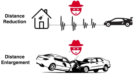
Distance Enlargement
Distance Reduction
Figure 1: Ranging systems are vulnerable to distance reduc-tion and enlargement attacks.
and preventing their collision can be achieved only if they are able to calculate their relative positions accurately and securely. Figure1shows that an adversary can manipulate the perceived distance between two mutually trusted devices by the distance reduction and enlargement attacks.
Conventional ranging systems, such as GPS and WiFi Po-sitioning Systems (WPS) [34], are useful for benign environ-ments and coarse-granular geolocation. However, they pro-vide insufficient precision for accurate distance estimations (e.g., cm-level granularity), suffer availability constraints (e.g.,
indoors, outdoors), and are relatively slow to calculate loca-tions for fast and mobile autonomous systems. More impor-tantly, the aforementioned ranging systems are susceptible to various spoofing attacks [4,14,28].
are bounded by the physical characteristics of the media, and cannot be sped-up. For example, distance bounding protocols return an upper bound on the measured distance, armed by the fact that an adversary would not succeed in guessing (secret) bit level information [5,6]. Other techniques are based on tailoring modulations to prevent distance-reduction attacks at the physical layer [26]. None of these approaches prevent distance enlargement attacks.
Distance enlargement attacks can deviate vehicles from their intended paths, or cause physical collisions. Existing protection approaches rely on dense, and often fixed, verifi-cation infrastructures,e.g.,towers. These may not exist, and often do not; installing them in outdoor settings is a costly affair, and not necessarily feasible (e.g.,in drone-based mili-tary missions behind enemy lines). Distance enlargement is a more devastating attack than distance shortening because an adversary in the communication range only needs to annihi-late (cancel) [23] or distort the authentic signals to prevent the receiver from identifying them and using their time-of-arrival (ToA) for ranging. The adversary then simply replays a de-layed version of the authentic signals, which it has already received by positioning itself in the vicinity of the sender or the receiver. The adversary need not guess these signals, nor compromise any upper-layer protocols to do that. The amount of delay corresponds to the adversary-intended distance to enlarge. In a collision-avoidance system of automobiles or self-driving cars for example, a few meters (⇠a few nanosec-onds) could be catastrophic.
We presentUltra-Wideband Enlargement Detection (UWB-ED)—the first known modulation technique to detect dis-tance enlargement attacks against UWB ranging based on ToF. UWB-ED relies on the interleaving of pulses of different phases and empty pulse slots (i.e.,on-off keying). Unable to perfectly guess the phase, this leaves the adversary with a 50% chance of annihilating pulses (similarly for amplification). As a result, some of the affected (authentic) pulses will be ampli-fied, while others will be annihilated. Unaffected pulses will remain intact, while positions that originally had no pulses may now have adversary-injected ones. The technique pre-sented herein gets the receiver to seek evidence indicating whether such a deformed trail of pulses in the transmission was indeed authentic, albeit corrupt.
Similar to Singh et al. [26] (which addresses distance-reduction attacks), we leverage a randomized permutation of pulses. However, unlike [26], we cannot simply look for whether these are out of order, and ignore them if so be-cause that is precisely the adversary’s objective in distance-enlargement: misleading the receiver to ignore the authentic signals. Instead, UWB-ED checks the energy distribution
of pulses: comparing the aggregate energies of a subset of pulses at the positions where high energy was expected (as per the sender-receiver secret pulse-permutation agreement), with others where low energy was expected. To subvert this, the ad-versary would be forced to inject excessive energy throughout
the whole transmission, which could then be detected using standard DoS/jamming-detection techniques.
We derive the probability that an adversary succeeds in a distance-enlargement attack against UWB-ED. This is also useful in setting input parameters,e.g.,balancing an applica-tion’s security requirements and ranging rate, while account-ing for channel conditions. For example, we show how proper parameterization of UWB-ED limits an adversary’s success probability in enlarging distances to<0.16⇥10 3.
In summary, the paper’s contributions are twofold.
• UWB-ED—a novel, readily-deployable modulation tech-nique for detecting distance enlargement attacks against UWB ToF ranging systems, requiring absolutely no ver-ification infrastructure, and making no impractical as-sumptions limiting adversarial capabilities.
• Analytical evaluation to UWB-ED, where the probability of adversarial success is derived as a function of input parameters and channel conditions. This evaluation is also validated using simulations.
The sequel is organized as follows. Sections2and3provide background and detail the threat model. The new distance enlargement detection technique is explained in Section4, and evaluated in5. Section 6complements with a related discussion, and7is related work. Section8concludes.
2 Background and Motivation
A device’s position can be estimated using the distances be-tween itself and other landmarks with known locations; or it could be expressed using a coordinate system,e.g.,in a Cartesian plane. The distance between two devices can be measured using radio signal properties, such as received sig-nal strength [3], phase [30], or the signal’s propagation time including ToF and ToA [15]. Reduction or enlargement of the calculated distances can lead to wrong positioning.
Adversarial distance reduction has been analyzed in pre-vious literature [31], but limited work was performed on en-largement attacks. Preventing enen-largement is achieved when a node is inside a polygon determined by an infrastructure of devices/towers, where verifiable multilateration [31] is ap-plied. Enlargement attacks are harder to detect without an infrastructure. Signal strength-based systems do not provide strong security guarantees during high variations of signal strengths in some channel conditions. For distance reduction attacks, the adversary can amplify a degraded signal but for enlargement, degradation is in the adversary’s favor.
2.1 UWB
IEEE 802.15.4a and IEEE 802.15.4f have standardized im-pulse radio UWB as the most prominent technique for pre-cision ranging. IEEE 802.15.4z [2] is in the process of stan-dardizing UWB to prevent attacks on the ranging systems. Off-the-shelf UWB ranging systems were recently devel-oped [1,9,13,35], and the research community/industry has expressed tremendous interest in these systems (e.g.,for au-tonomous vehicles). Because current standards do not prevent enlargement attacks, it is important to mitigate them before standards are deployed in practice.
Symbol Structure. UWB systems operate over wide seg-ments of licensed spectrum. They have to be compliant with stringent regulatory constraints. Firstly, the power spectral density should not exceed 41.3dBm/MHz, averaged over
a time interval of 1ms. Secondly, the power measured in a 50MHz-bandwidth around the peak frequency is limited to 0dBm. Due to these constraints, the power per pulse is limited. To support longer distances, the energy of multiple pulses is aggregated to construct meaningful information. Figure 3 shows On-Off-keying (OOK) modulation, as used in IEEE 802.15.4f-based UWB ranging systems. Each symbol has two pulses and two empty slots. The symbol length is repre-sented asTband the spacing between consecutive pulses isTs. Information bits are encoded in the position of the pulse.
Symbol Detection. Figure 2 shows a conventional non-coherent energy detector (ED) receiver [32]. The energy de-tector receiver is consist of square-law device to compute instantaneous received signal power and an energy integrator. For the received signalr(t), the output of the receiver can be expressed as:
E(k) =
Z Ts⇤k+TI
Ts⇤k [r(t)]
2dt (1)
where Ts⇤kis the integration start time,TI the integration window size, andTsthe spacing between consecutive pulses.
These receivers perform squaring and integration, making phase information irrelevant for pulse detection. In the case of multi-pulse per symbol, the energies of multiple pulses are aggregated. For the orthogonal hypothesis testsH1andH0
for bit 1 and 0 respectively, the decision of the ED receiver is made in favor of the positions with higher energy.
b(i) =
(
0 EH0(i) EH1(i)
1 EH0(i)<EH1(i) (2)
2.2 Distance-Enlargement Attack
In contrast to reduction attacks, to enlarge the distance, the adversary need not predict the authentic signal. Instead, it re-plays the authentic signal by replaying an amplified version of
Bandpass
filter
(
·
)
2 TI
0
dt
E(i)
Decision
r(t)
Figure 2: Non-coherent energy detector receiver.
Tx R t a) Replay
t+
t+
Ts
Ts
t
Tb, bi+1= 1
Tb, bi= 0 Np= 2
Tx
Rx
b) Annihilate and Replay Tx t R
t+
t
tt+
Ts
Rx
Tx R t+
t+
Ts time
Rx
c) Relay t
Legitimate Signal
Attack Scenario
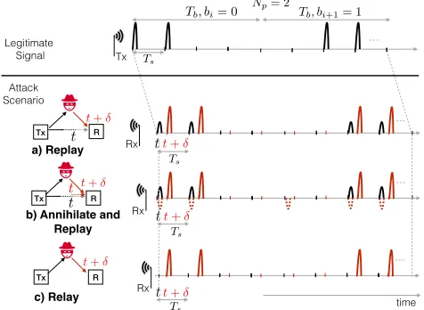
Figure 3: Various attack scenarios on UWB.Black and red colors represent authentic and adversary signals respectively. Dotted red represent adversarial signal-annihilation attempts.
it after some delay. The receiver gets both, authentic and adver-sary’s signal superimposed. Because these authentic signals also reach the receiver, the adversary cannot control how the receiver processes them. None of the existing ranging systems is secure against enlargement attack- be it UWB -802.15.4z, WiFi- 802.11, or GPS. Signal replay is a typical strategy to mount distance enlargement attacks. Other enlargement at-tacks, such as jamming, alters the output of the receiver’s automatic gain control (AGC), and are likely to expose the adversary [22,27]. Complementing signal replay by signal annihilation prevents the receiver from detecting the authentic signal. Annihilation is possible due to the predictable symbol structure.
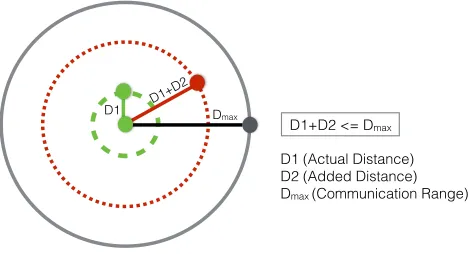
D1 D1+D2 Dmax
D1 (Actual Distance) D2 (Added Distance) Dmax (Communication Range)
D1+D2 <= Dmax
Figure 4: IfD1+D2>Dmax, the devices realize they are
outside each other’s communication range without the need to run distance-enlargement detection protocol.
In Fig.3a, an authentic signal reaches the receiver at timet, and the adversary’s signal att+d. If the receiver backtracks in time (searching for earlier-received signals), the authentic signal will be encountered. Figure3b shows how the pre-dictability of the symbol structure enables an adversary to annihilate its pulses (by emitting a reciprocal pulse phase), preventing the receives from detecting it. Figure3c shows the case when nodes are not in the communication range (or signal is attenuated by channel condition); the receiver does not get authentic signals, just adversary-relayed (and delayed) signals.
3 Threat Model
We focus on the scenario where there are two devices in a wireless network that are interested to securely measure the physical distance between them, and protect the measure-ments from a third-party adversary. The devices know their maximum communication range. The adversary’s objective is to enlarge the distance that the devices measure. The adver-sary cannot directly block or modify messages on the channel (cf.Dolev-Yao’s adversary [10]); it can rather inject signals, and through such injection it can block/modify the authentic signals. If successful, this injection can lead to jamming, sig-nal annihilation, and/or content modification. This model cap-tures the capabilities of man-in-the-middle (MITM) attacks in wireless settings, and is typical in previous literature [7,12]. The model also fits well with our target application scenario: the communicating devices are typically mobile and move (drive or fly) in formation. In such scenarios, it is unlikely that an adversary prevents the signals of one device from reaching the other by physical obstacles, and is thus limited to injecting signals.
We assume the adversary is able to communicate and listen on any channel the devices use. However, because the devices are communicating over UWB, the adversary is unable to de-terministically annihilate pulses without knowing their phase
(positive or negative). Existing hardware is not fast enough to enable the adversary to sample a pulse’s phase and react by injecting the reciprocal pulse promptly due to the very narrow UWB pulse width of⇡2 ns. We therefore assume that the adversary will not be able to deterministically anni-hilate pulses from the channel, only with some probability
<1. It succeeds in annihilating pulses if it guesses the phase of the pulse correctly. We over-approximate the adversary by providing the capability to synchronize attack signal with the authentic transmission. Signal synchronization is a hard problem, but an adversary can achieve it by using stable clock and distance information.
We assume the adversary knows the actual physical dis-tance between the two devices at any point in time. The ad-versary can calculate this using several means,e.g.,by eaves-dropping on unencrypted position announcements the devices make. The adversary can also position itself along the direct path between the two devices, measure the distance between itself and each from that position, and add both distances. To measure these distances, the adversary’s device can perform two-way ranging with each device independently, pretending to be the other device; or even without such impersonation, it could perform one-way ranging after synchronizing its clock with each device separately.
We assume the devices themselves are not compromised; the adversary cannot attach a physical cable to their inter-faces, nor hijack their firmware. However, the adversary can have multiple network cards and antennas, and is not energy-bounded. It can be stationary or mobile.
UWB-ED (Section4) involves transmitting, between the victim devices, a code of n pulses, a of which are data-representing, and the remainingbare absent of energy, where
n=a+b. We assume the adversary knows the values ofa andb, but not the positions of these pulses in the transmis-sion. (Their positions are determined by both devices pseudo-randomly in each transmission.) The adversary can learn these parameters by remaining passive in the vicinity of the victim devices, silently observing their transmissions.
Finally, we assume that it is not in the adversary’s interest to prevent the devices from communicating,e.g.,by shielding them, or jamming the channel.
4 UWB-ED Design
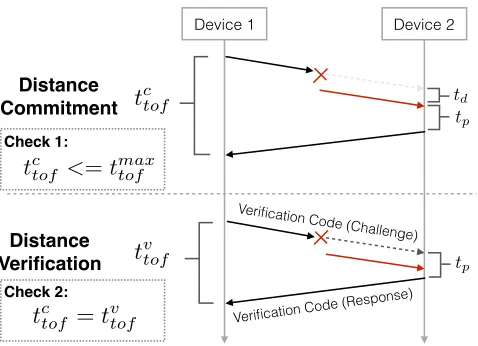
UWB-ED consists of two phases conducted between both devices: Distance Commitment and Distance Verification. Figure5shows a timing diagram of both phases. In the first, the devices measure the distance between them using a two-way ranging protocol. The distance measured in this phase (tc
to f) should not exceed the supported communication range
(tmax
to f ). In the distance verification phase, the devices measure
Distance Commitment
Distance Verification
tp
tp
td
Verification Code (Challenge)
Verification Code (Response)
t
vtoft
ctofDevice 1 Device 2
Check 1:
Check 2:
t
ctof<
=
t
maxtoft
ctof=
t
vtofFigure 5: Timing diagram of UWB-ED operation. See inline (Section4) for notation.
attack is detected when such traces are found,tc
to f >tto fmax,
or when tc
to f 6=tto fv (Fig. 5). By enlarging distance in the
commitment phase, the adversary increasestc
to fbytd, but fails
to enlarge the distance in the verification phase. Annihilation attempts on the challenge frame are shown, but the adversary can also attack responses from both devices.
Distance Commitment Phase.The devices measure se-cure upper bound by using distance bounding along with secure modulation techniques [5,6,26]. This provides strong guarantees against reduction attacks but is susceptible to enlargement attacks. The distance committed in this phase should not exceed the communication range (i.e.,an enlarge-ment attack is detected whentc
to f >tto fmax). This check ensures
that the nodes can communicate without a relay. An adversary enlarging distance by more than the communication range is also exposed using this check.
Distance Verification Phase.In this phase, the committed distance is verified,i.e., an enlargement attack is detected whentc
to f 6=tto fv . To achieve this, the devices measure their
distance using round-trip time-of-flight, with both challenge and response messages protected using specially crafted ver-ification codes(i.e.,special UWB-ED modulation). In this exchange, the sender initiates the distance verification phase by transmitting a verification code; the receiver tries to detect the presence of that code, or traces thereof, in the transmis-sion, despite the adversary’s efforts totrail-hideits existence from the channel (Section2.2). The verification code and its check is applied to both time-of-flight messages. Both devices first agree on the code’s structure as follows.
4.1 Modulation/Verification Code Structure
Code length.The code consists ofnpositions,aof which have energy, and the remaining b=n a are empty,i.e., absent of pulses (conceptually similar to OOK modulation,
1 2 3 4 5 6 7 8 9 10 11 12 13 14 15 16 17 18
Original:
Permuted:
Figure 6: An example verification code with a randomly-looking pulse reordering, wherea=5,b=13, and the code containsn=a+b=18 pulses. Upon receiving the permuted code pulses as per the secret agreement between the sender and receiver, the receiver knows that Bina will contain the
received energies at the positions (gray) {2, 6, 7, 13, 15}, which are the expected high-energy pulses. Binbwill contain
the rest: {1, 3, 4, 5, 8, 9, 10, 11, 12, 14, 16, 17, 18}.
wherea=b). The code length affects the performance and security of the presented modulation technique. Largera andbvalues improve the security by reducing the probabil-ity of adversarial success in mounting undetectable distance-enlargement attack. However, increasing the code length re-duces the frequency of conducting two-way ranging. Addi-tionally, the Federal Communications Commission (FCC) imposes restrictions on the number of pulses with energy, effectively limitingaper unit of time. As such,bcould be independently increased to compensate for the loss of code length. Setting these parameters is discussed in Section5.
Pulse phase.The sender uses a random-phase for thea pulses it transmits. Each phase is equally likely. The phase will be irrelevant for the receiver because ED receivers are agnostic to the phase, as explained in Section2.1. The sender need not share this information with the receiver since the receiver measures the energy, not the polarity of the pulse.
Pulse permutation.The sender and receiver secretly agree on a random permutation of thenpositions, obtained from a uniform distribution. Figure6shows an example before and after the permutation. The verification code can thus be considered a sequence of{ 1,0,1}pulses, where{ 1,1}
represent the phase, and{0}pulse absence.
Spacing between pulses.The time between two consec-utive pulses,Ts, is normally lower bounded by the delay spread of the channel. We submit thatTsshould be such that
Ts>2d/c, wheredis the distance between the two devices.
If the adversary replays the authentic signal delayed by more than the equivalent RTT, the attack will be detected by the mismatch between the measured RTT and the one equiva-lent to the committed distance. To avoid being detected, the adversary would thus replay its delayed version of a pulse within theTstime window. As such, authentic pulseiwill not overlap with the adversary’s delayed version of pulsei 1, or any further adversary pulsesi 2,i 3,etc.
Figure 7: An example verification code ofnslots (9 of which are shown), the spacingTsbetween consecutive pulses is 1µs
and pulse widthTpis 2ns. An adversary transmits a pulse to distort the legitimate pulse (dashed red). The adversary also replays the authentic signal with the delayd(solid red). Best viewed in color.
4.2 Verification Code Identification
Upon receiving a transmission, the receiver starts processing the code associated with the highest preamble’s peak. The code associated with a peak is the train ofTs-spaced pulses that start at a fixed time interval (e.g.,agreed upon between the sender and receiver) after the peak. This peak however may not be authentic, and could be the adversary’s replayed version. The receiver thus backtracks at fixed time steps cor-responding to the pulse widthTp(e.g.,2ns), trying to identify if another version of the code (or a possible distorted im-print of it) was present in the transmission at an earlier time. The receiver does not need to backtrack further beyond some timeT0, knowing the maximum communication range. If the
last distance verification occurred recently, the verified range could be used (in combination with the devices’ upper bound motion speeds) to reduce the backtracking time.
Backtracking requires the receiver to record transmissions. If an earlier version of the code is found (and their difference exceeds the receiver’s standard precision,e.g.,±10cmfor DecaWave [9]), it is used for ToF estimation.
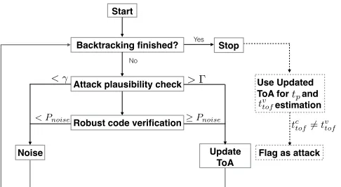
As shown in Fig.8, the receiver performs Attack Plausibil-ity check and Robust Code Verification to detect attacks until the maximum backtracking time is reached. For each code, the receiver does not look for an exact match of the transmitted pulses in their positions simply because that could be easily bypassed with minimal adversarial efforts (as explained in Section2.2). Instead, the receiver proceeds as follows. Know-ing the mappKnow-ing of the pulse positions, the receiver distributes the received powers of each pulse among two bins, Binaand
Binb. The former will have the values of the received power
(e.g.,in Watts) of the energy-present pulse positions, the latter energy-absent positions (Fig.6).
Attack Plausibility check.For each candidate verification code obtained during backtracking, the overall received sig-nal power (the aggregate of Binaand Binb) is measured, and
Robust code verification
Noise Update
ToA
< Pnoise Pnoise
Stop Backtracking finished?
No
Yes
Attack plausibility check
< > Use Updated
ToA for and estimation
tp
Start
tv tof
Flag as attack tc
tof6=tvtof
Figure 8: The receiver backtracks to detect enlargement at-tacks. An event is flagged as an attack when the aggregate energy is higher thanG(e.g.,DoS, jamming),i.e.,the data looks more similar to a verification code than noise. The last flagged position is used for the ToF estimation.
compared to a predefined threshold,g. This threshold is based on the receiver’s noise figure. If the aggregate exceedsg, a potential verification code has been found. Otherwise it gets discarded as noise. The aggregate energy is then compared to another threshold,G. This is calculated based on the overall aggregate energy the receiver expects to receive based on the measured distance in the commitment phase, following the path loss model. Artificial distance enlargement caused by the adversary in the commitment phase lowers the receiver’s cal-culatedG(because of the higher path loss), thus increases the likelihood of the actual received aggregate to exceedG. If the aggregate exceedsG, an adversary may possibly be injecting energy into the channel to distort the authentic code. If the verification code is neither discarded as noise (<g) nor ex-ceedsG, the receiver proceeds to the Robust Code Verification check.
Robust Code Verification.Now the receiver checks the verification code content. If the receiver simply flags the pres-ence of one or more pulses (above noise) in Binbas an attack,
false positives increase because such pulses could occur for many legitimate reasons (e.g.,noise spikes, reflections, in-terfering transmissions, antenna orientation, or multipath).1
Instead, the receiver performs a sequence of binary hypothesis tests on random pulse samples. It tests if the candidate code is more similar to an authentic code than noise. It choosesra random pulses from theain Bina(whereris the number
of pulses per symbol), aggregates their received powers and compares that to the aggregate of anotherrpulses randomly chosen from thebin Binb. If the aggregate of those selected
from Binais larger, the receiver identifies this as a candidate
authentic code, and records its ToA. Finally, the distance is calculated based on the recorded ToA of the most recently
1If the receiver instead interprets a pulse in Bin
bas an indication that the
received code, and a mismatch with the committed distance is flagged as an attack.
A candidate verification code could be again noise, which has slipped the Attack Plausibility check perhaps due to some sporadic noise spikes in the transmission. Noise has a proba-bility ofPnoiseto satisfy the Robust Code Verification check,
wherePnoiseis derived as (32) in Section5.1.4. As such, the
receiver estimates the probability that the above condition is satisfied. This is done by repeating the random samplingu times, and checking if the ratio of the number of times the condition is satisfied touexceedsPnoise. This would indicate
the code is not noise, and is either authentic or adversary-replayed. Regardless, the receiver uses the ToA of the most recent code found.
4.3 Setting the Energy Thresholds.
Setting the upper-bound threshold,G.To setG, the receiver relies on the committed (unverified) distance between itself and the sender. This dictates the path loss—the amount of power loss per pulse as pulses propagate the medium. Larger committed distance causes the receiver to expect less power, thus setting a lowerG. Thus, by increasing the committed distance, the adversary helps divulge its malice.
The path loss function f()for outdoor UWB LoS is [20]:
f(d) =PL0+10·n·log ✓d
d0 ◆
(3)
wheredis the distance in meters, andPL0is a constant
repre-senting the path loss at the reference distanced0. For UWB
LoS channel model, these constants are set to [20]:
f(d) = 46.3 20log(d) log
✓6.5
5
◆
(4)
This is calculated in the standard signal ratio unit,dB, where:
Power ratio (indB)=10log(ratio) (5)
The path loss function thus expresses the power loss as
f(d) =10log
✓
(lb)2
(lsent)2 ◆
(6)
or
(lb)2
(lsent)2=10
f(x)/10 (7)
where (lb)2 is the pulse instantaneous power the receiver expects, and(lsent)2is that the sender has actually sent,e.g.,
both in Watt. Knowing the constant pulse power of the sender, then the pulse power is expected to be received as:
(lb)2= (lsent)210f(x)/10 (8)
The receiver then calculatesGas follows:
G=a(lb+N)2+b(N)2 (9)
whered is the (unverified) distance in meters between the sender and receiver obtained at commit stage, either true or artificially enlarged in case of an attack.Nis an instantiation of zero-mean Gaussian noise at the receiver,i.e.,the noise present in the receiver’s channel and cannot be removed [19].
There are other factors that contribute to the degradation of power. These factors could cause further power lossE, typically up toE = 8 dB more [17,21]. If the receiver setsGas that after the expected further degradation (i.e.,too smallGvalue), false positives may increase because such additional signal-degradation factors may or may not occur— if they do not, the receiver would then falsely assume such relatively “too high” aggregate energy is due to an attempted attack. Accordingly, the receiver sets Gbased only on the (almost certain) path loss deterioration. Any further power loss would then be added benefit to the adversary, as it allows the adversary to inject more pulses into the channel to corrupt the authentic code without exceedingG.
Setting the lower-bound threshold,g. If the aggregate energy is<g, it would be either due to noise or a substan-tial deterioration of the authentic signal where no meaning-ful information could be recovered during the Robust Code Verification. Too highgleads to false negatives; too low trig-gers Robust Code Verification even for noise. For critical applications seeking to prevent false negatives,gcould be set conservatively based on the receiver’s noise variances2
N:
g= (a+b)·s2N (10)
4.4 Attack Resilience
Here we explain how UWB-ED resists standard enlargement attacks. More complex attacks are discussed in Section6.
4.4.1 Detecting Signal Replay
An adversary that simply replays authentic pulses does not win because the receiver backtracks to detect earlier copies of the code. UWB-ED provides resilience to benign signal dis-tortion,e.g.,due to channel conditions or antenna orientation, because the receiver looks for similarities between the code and the received signal (versus exact data match), allowing for a higher bit error rate. In general, poor channel conditions (low SNR) can be compensated for by increasing the symbol length,r, minimizing the bit error rate.
4.4.2 Complicating Signal Annihilation
0 20 40 60 80 100 10 10
10 9
10 8
10 7
10 6
10 5
Actually-received signal
Receiver’s threshold per pulse
Distance (m)
Po
wer
loss
ratio
(10
f
(
x
)
/
10)
Best receiver-expected signal
E= 5dB
E= 10dB(worst)
Figure 9: The best expected signal power as calculated by the receiver using the path loss function in (4), the signal at
E= 5dbof further power loss, and atE= 10db(worst expected). If the distance isD1=15.11m(green line), and
the adversary doubles it,i.e., by adding D2=15.11 mto
make itD1+D2=30.22m(red line), the receiver will set
the threshold following the fake distance, at 10f(D1+D2)/10=
10 7.6. The adversary’s room is the difference between the red
and green lines on they-axis. AtD2=32.68m, the adversary
has no room. Best viewed in color.
now needs to compensate with an equivalent amplitude,A. Amplification doubles the amplitude. The estimated energy of the pulses will thus amount to⇠A2, and the
adversary-contributed amplification to⇠(2A)2.
Since the result is indeterministic for the adversary, it leads us to the next discussion: how successful would the adversary be in “contaminating the evidence” that an authentic veri-fication code existed, and how much energy room does the adversary have to do that before exceedingG?
4.4.3 Mitigating Evidence Contamination
To hide the authentic code, the adversary tries to inject energy into the channel, hoping it annihilates as many of Binapulses
as possible. We thus calculate the room available to the adver-sary here, and use that to derive the probability of adversarial success in distance enlargement in Section5.
Figure9shows the path loss function in (7) as used by the receiver to detect the thresholdG, as well as the worst receiver-expected signal after additional deterioration. The receiver sets the threshold based on the best expected signal. The room available for the adversary to add energy depends on the actual signal received. The most favorable situation to the adversary is when the received signal power is the worst (lowestE), which allows the adversary to inject pulses without exceeding G. For example, in Fig.9, if the actual distance between the sender and receiver is D1=15.11m (green line), and the
0 0.5 1 1.5 2 2.5 3 0
5 10
Adversary-added distance ratio (D2/D1)
Adv
ersary
room
(
z
)
E= 10dB
E= 5dB
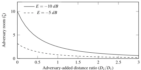
Figure 10: Adversary’s room to add energy,zin (12), against the ratio of the adversary-added to true distance (D2/D1);E
represents additional signal degradation beyond path loss.
adversary is trying to addD2=32.68mto make the distance
D1+D2=47.79m(red line), the receiver will setGusing
the fake distance,D1+D2. At such a relatively large added
distance,D2, the received pulse power is unlikely to fall below
f(D1) +E=10 8(lsent)2at,e.g., E= 10dB. The room
available to the adversary to inject energy becomes too small, significantly reducing its chances of success.
The room-per-pulse,R, available to the adversary to enlarge the distance thus lies in-between the received signal andG, and is calculated indBas:
R= f(D1+D2) (f(D1) +E) (11)
whereErepresents other channel degrading factors, and the distancesD1 and D2 (in meters) are respectively the true
distance between both devices, and the extra distance the adversary intends to add. This room is thus expressed as:
z=10R/10 (12)
Figure10plotszat various distance ratiosD2/D1.
Recall that the adversary may succeed to annihilate some of the pulses falling in Bina. But since Binbin the authentic
code have nothing but noise, adding pulses into those will result in an increase in the overall aggregate energy. As such, this available energy room in (11) by itself does not give a perfect indication to the adversary’s chances of success.
4.5 A Numerical Example
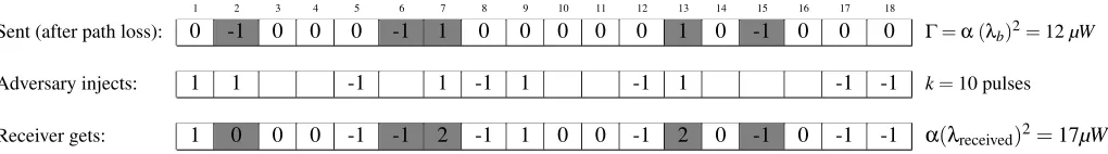
Figure11shows an example verification code, expanded from Fig.6, where the adversary injectsk=10 random-phased pulses. For simplicity, the figure assumesN=0. If the dis-tance between the sender and receiver isD1=4m, and the
adversary is trying to enlarge it byD2=4.5 mto make it
D1+D2=8.5m, and assuming(lsent)2=7.6µW, then the
receiver expects a best case received power of:
(lb)2= (lsent)210f(D1+D2)/10
1 2 3 4 5 6 7 8 9 10 11 12 13 14 15 16 17 18
Sent (after path loss): 0 -1 0 0 0 -1 1 0 0 0 0 0 1 0 -1 0 0 0 G=a(lb)2=12µW
Adversary injects: 1 1 -1 1 -1 1 -1 1 -1 -1 k=10 pulses
Receiver gets: 1 0 0 0 -1 -1 2 -1 1 0 0 -1 2 0 -1 0 -1 -1 a(lreceived)2=17µW
Figure 11: An example of the random-phased Binapulses (dark gray) reordered following the permutation in Fig.6. After the
adversary injectsk=10 random-phased pulses at random positions, the receiver will get the summation at each pulse position.
From (10) atN=0 anda=5 (as in Fig.11), it then calculates the threshold as:
G=a(lb)2=12µW (14)
AtE= 10dB, the actual signals are received as:
(lw)2= (lsent)210(f(D1)+E)/10⇡1µW (15)
Now assuming the adversary isD3=6maway from the
receiver, and uses a random-phased pulse with transmission power of(ladversarysent )2=15.77µW. AtE= 10dB, the re-ceiver would receive the adversary’s signals as:
(l0)2= (ladversarysent )210(f(D3)+E)/10⇡1µW (16)
So in the best case for the adversary, where the signal is highly deteriorated, the adversary would then have a per-pulse room ofR=3.45dBto add energy, which amounts to 7µW
more,i.e.,up toG=12µW. In Fig. 11, after the adversary injects itsk=10 pulses at the example random positions and with the random phases shown, it results in annihilating a single pulse (at position 2), amplifying two pulses (at posi-tions 7 and 13), and adding seven more 1µW pulses for an increase of the overall aggregate to be 17µW. This exceeds G=12µW, and this attack would thus be detected.
5 Evaluation
We evaluate UWB-ED by deriving the probability of success for an adversary enlarging the distance. We also validate that model using simulations in Section5.2.
5.1 Probability of a Successful Attack
The adversary hides the authentic code by having the aggre-gate of therpulses that the receiver chooses from Binbexceed
Bina. The adversary must also avoid injecting too much
en-ergy to not exceedG. Not knowing which pulse belongs to which bin, the adversary injectskpulses at random positions thus affectingkof thenpulses in the code.
To that end, the probability of mounting a successful attack,
Psa, is the intersection of the probability of two events (the checks in Fig.8): the aggregate of the energy pulses chosen
from Binb (bb) exceeds that of Bina (ba), and the added
energy isG:
Psa(a,b,r,G,k) =Pbb>ba(a,b,r,k)\PG(a,b,k) (17)
5.1.1 Probability of successfully evading the Robust Code Verification check (Pbb>ba)
To evade this, the adversary must have an energy aggregated from Binbexceed Bina. When the adversary injectskpulses
into the channel,xwill fall into Bina, and the remainingk x
into Binb.Pbb>bais then the probability of this distribution
occurring multiplied by the probability of the attack succeed-ing under this distribution, for all possible such distributions 0xaand 0k xb. To calculate the probability of the distribution occurring, consider the general case of a bucket containing two types of objects (e.g.,colored pearls):I
of the first type, andJof the second. Ifyobjects are selected at random, the probability thatiand jof theyare respectively of the first and second type (i+j=y) is:
I i Jj
I+J i+j
(18)
where nr denotesnchooserand is given by:
✓n
r
◆
=
8 < :
n!
r!(n r)!, 0rn
0, otherwise
Similarly, the probability thatxandk xof the adversary’s
kpulses respectively affect theain Binaandbin Binbis:
a
x k xb
a+b
k
For all possible such distributions, we have:
Pbb>ba(a,b,r,k) = a
Â
x=0
pa,b,r,k(x)·
a
x k xb
a+b
k
!
(19)
wherepa,b,r,k(x)is the probabilitybb>bagiven the
adver-sary affectedxandk xpulses in Binaand Binbrespectively.
To derive pa,b,r,k(x), we assume for simplicity a unity
reach the receiver after path loss and other factors at a con-stant energy of±1µW.2This is similar to the example given
in Fig.11. Every adversary-added pulse in Binbwill result
in a 1µW of added energy from the receiver’s point of view since the receiver’s aggregation is agnostic to a pulse’s phase. For Bina, after the adversary affectsxpulses, some will be
annihilated while others will be amplified. From the receiver’s point of view, after the adversary’s pulses are injected, Bina
will have a mix of 22=4µW and 0µW (adversary-affected)
pulses, as well as the original 1µW unaffected pulses. More 0µW (annihilated) pulses in Binaraises the chances
thatbb>ba, which is in the adversary’s favor. Since every
affected pulse in Binawill either result in a 0µW or a 4µW
pulse, there are 2x possible outcomes. Of those, there are x
g ways thatg0µW pulses will occur. The probability that
thexadversary-injected pulses that fell in Binaresult in a
annihilation ofgpulses is thus gx /(2x). For all possible
num-bers of annihilated pulses 0gx, the adversarial success probability in the event thatxfell in Binais:
pa,b,r,k(x) = x
Â
g=0
pa,b,r,k,x(g)· x g
2x
!
(20)
wherepa,b,r,k,x(g)is the probabilitybb>bagiveng
annihi-lated pulses in Bina.
When Binahasgannihilated (0µW),x gamplified (4
µW), anda xunaffected pulses (1µW), the probability of
bb>bain the eventxfell in Bina, andgof thexpulses were
annihilated is the probability that an aggregate ofm 1 is chosen from Binaand an aggregate of mis chosen from
Binb. For each possible 0y1,y2r, we have:
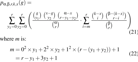
pa,b,r,k,x(g) =
r
Â
y1=0 r
Â
y2=0 g y1
x g y2
a x
r y1 y2
a
r ·
r
Â
i=m k x
i b r i(k x)
b
r
!
(21) wheremis:
m=02⇥y1+22⇥y2+12⇥(r (y1+y2)) +1
=r y1+3y2+1 (22)
Atr=a(i.e.,selecting all Binapulses) andab, we get:
pa,b,r,k,x(g) = r
Â
i=m0
k x
i b r i(k x)
b
r
(23)
wherem0is:
m0=22
⇥(x g) +12⇥(a x) +1
=4(x g) + (a x) +1 (24)
Figure12plotsPbb>ba, wherea=50. From these results,
increasingbis not necessarily effective for the Robust Code 2Analogous analysis applies for non-constant energy.
0 50 100 150
0 1
# of adversary pulses (k)
Probability
(
Pbb
> b a ) r=1 r=2 r=4 r=8
(a)b=100
0 20 40 60
0 1
# of adversary pulses (k)
Probability
(
Pbb
> b a ) r=1 r=2 r=4 r=8
(b)b=10
Figure 12: Probability that the Robust Code Verification check fails to detect the adversary’s attack, plotted using (19) in Section5.1.1, ata=50 and 0ka+b.
Verification check to detect attacks, since the adversary main-tains its success probability by increasingkproportionally; there is a visually similar pattern of adversarial success proba-bility in both Fig.12aand12b. As such, the advantage of the empty pulses in Binbdoes not quite manifest in the Robust
Code Verification check, rather the Attack Plausibility check. Another observation is that higherrlowers the adversary’s success probability. For example atb=100 (Fig.12a), the adversary has a 27% chance atr=2 (which occurs atk= 135), versus 5.85% atr=8 (atk=130). In Section5.1.3, we show that atr=a, we get the optimal security results.
5.1.2 Final Probability of Adversary’s Success
In (17), the event that the aggregate energy after the adver-sary’s pulses isGand the event thatbb>baare dependent,
and thus their intersection is not their product. Recall that in (20),gis the number of annihilated pulses,x gis the number of amplified pulses in Bina, andk xis the number of added
pulses in Binb. The aggregate-energy does not exceedGwhen
the adversary’s pulses satisfy the inequality:
(k x) (l0+N)2+ (x g) (l0+lw+N)2+
(a x) (lw+N)2+ (b (k x) +g) (N)2G
(25)
wherel0is defined as in (16), andGin (10).
If the adversary uses a variable pulse power randomly cho-sen from a distribution with a mean much different fromlw,
authentic pulses colliding with their reciprocal will not be fully annihilated. The adversary thus sets its power such that its mean at the receiver matches the sender,i.e.,(l0)2= (lw)2.
Assuming(lw)2= (l0)2in (25), we get:
k+2x 4d+aa l
2
b e
l2
w (26)
Ase!0, (26) becomes:
k+2x 4da
✓l2
b
l2 w 1
◆
(27)
From (13) and (15), we have:
l2
b
l2 w =
(lsent)210f(D1+D2)/10
(lsent)210(f(D1)+E))/10
=10(f(D1+D2) (f(D1)+E))/10
=z
(28)
wherez, from (12), represents the room-per-pulse available to the adversary to add energy into the channel.
We now calculatepa,b,r,k(x,G), similar to (20) as:
pa,b,r,k(x,G) = x
Â
g=0
pa,b,r,k,x,G(g)·
x g
2x
!
(29)
such that
pa,b,r,k,x,G(g) =
(
pa,b,r,k,x(g), k+2x 4da(z 1)
0, otherwise
(30) Using (29), the final adversarial success probability is:
Psa(a,b,r,G,k) =
a
Â
x=0
pa,b,r,k(x,G)·
a
x k xb
a+b
k
!
(31)
Figures13aand13bplotPsa in (31). Atz=20,Gis too
high to reducePsa, but the Robust Code Verification check
enables the receiver to limit it toPsa<0.16⇥10 3. Atz=
10,Psastops growing beyond 0.73⇥10 4, which limits the
adversary’s pulses tok=495 for its highest success chance. Figure13cshows the effect ofbonPsa;Psais almost
con-stant withb, at around 0.2⇥10 3, and only starts dropping
whenbis sufficiently large so that the aggregate energy after the adversary’s pulses exceedsG. At a certain point, increas-ingbno longer helps. For example, atz=5 andb 400,
Psa⇡0.bshould thus be set wisely, reflecting the
applica-tion’s sensitivity to distance increases and channel conditions, to avoid increasing transmission lengths unnecessarily.
5.1.3 Symbol length (r)
Figures13dand13eplotPsa against the ratio ofr:a. As
shown, longer symbol length (largerr) is better for security; the best results are achieved when the ratio is 1 (r=a).
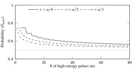
5.1.4 False positives: noise passing Robust Code Verifi-cation
Higher-than-usual noise in the channel might satisfy the Ro-bust Code Verification check. Since the receiver backtracks,
it is imperative to calculate the probability,Pnoise, that noise
in the channel satisfies that check. Unlike the adversary’s pulses targeted to alter the authentic code, such a candidate trail of noise pulses does not get added to the sender’s code because they are at different positions. Without loss of gener-ality, we can separate the noise-intervals in low-energy and high-energy,e.g.,across the median of the distribution ofN2.
We refer to the number of high-energy intervals ask. The probability that noise satisfies the Robust Code Verification check is the probability thatxofkpulses fell into Bina, by
the probability of satisfying the test in that event,p0 a,r(x):
Pnoise(a,b,r,k) =
a
Â
x=0
p0 a,r(x)·
a
x kbx
a+b
k
!
(32)
where,
p0 a,r(x) =
r
Â
y=0
a x
r y xy
a
r ·
y
Â
i=0
b (k x)
r i kix
a
r
!
(33)
This is the probability that an aggregate ofyis chosen from Bina, and ofyfrom Binb. Since we separate along the
median, the expectedkis(a+b)/2. Figure14plotsPnoise
againstausing (32) atk= (a+b)/2 andb=100. Intuitively (and as the chart confirms),Pnoise !0.5 asa !•.
Since a candidate verification code is discarded as noise if the Robust Code Verification check is satisfied with a probabil-ity<Pnoise(recall: Fig.8), the adversary must have a success
probability of at least 1 Pnoise to hide the authentic code
from the receiver. Atr=a,Pnoise(80,100,80,40) =0.53,
and the adversary must thus have a success probability of at least 0.47. As this is much higher than the calculated prob-abilities in Section5.1.2, the adversary will not be able to disguise authentic code as noise. The value 0.53 is a lower-bound; in practicePnoiseshould be set 0.53 depending on
applications’ requirements and channel conditions.
5.2 Validating the Probabilistic Model
200 300 400 500 0
2·10 4
# of adversary pulses (k)
Probability
(
Psa
) zz=20
=10
(a)b=500;r=a=50.
60 80 100 0
2 ·10 4
# of adversary pulses (k)
Probability
(
Psa
) z=20
(b)b=50;r=a=50.
200 400 600 800 0
4 ·10
4
Size of Binb(b)
Probability
(
Psa
)
z=20
z=15
z=10
z=5
(c)r=a=50.
0 0.2 0.4 0.6 0.8 1 10 4
10 3
10 2
10 1
Ratio (r:a)
Probability
(
Psa
)
z=20
z=10
(d)a=50 andb=500
0 0.2 0.4 0.6 0.8 1 10 4
10 3
10 2
10 1
Ratio (r:a)
Probability
(
Psa
)
z=20
z=10
(e)a=50 andb=50
Figure 13: Adversarial success probability in (31).
0 20 40 60 80
0.4 0.6 0.8 1
# of high-energy pulses (a)
Probability
(
Pnoise
)
r=a/4 r=a/2 r=a/1
Figure 14: Probability that noise passes the Robust Code Verification check, calculated using (32);k=a/2,b=100.
other ranging applications. The simulations account for the noise and interference due to the noise figure of the receiver and multipath components. To verify the simulation setup, we performed a thorough evaluation to cross-check simulation metrics with previous proof-of-concept implementation [26]. Each pulse uses 500 MHz bandwidth, and the sampling time between consecutive pulses is 1µs. Transmission power is limited to -35 dBm/MHz, well under the limits applied by the FCC/ETSI regulations [11]. The energy is further reduced to adapt to path loss model and extra losses (E;cf.Fig.9).
An adversary is simulated to injectksignals to annihilate or distort the authentic code, and to replay a delayed and amplified versions of the authentic signals. Similar to our assumptions, the adversary in the simulator is capable of annihilating the pulse and its multipath if the phase is guessed correctly; it doubles the amplitude of the pulse otherwise. The time difference between authentic and delayed signals is d=200nsin the simulations (see Fig.7).
Before demodulation, additive white Gaussian noise (AWGN) is added to the signal. The receiver in Section2.1is implemented for code verification; it always locks on to the highest peak,i.e.,the peak generated by the adversary due to its replay attack. The communication range is considered 100m, and the backtracking restricted to 660ns.
The goal of our validation is to (1) confirm the probabilis-tic model’s correctness, and (2) analyze the effect of the pa-rameters abstracted from the model, namely noise and the receiver’s ability to reconstruct the signal after long distance propagation. In practice, the latter point can be accounted for by increasing the number of pulses (n=a+b)—see below. Validating Pbb>ba. Figure 15 shows the validation for
Pbb>ba, at a simulated distance between both devices of
d=10m. A boxplot is drawn at distinctk, where each sce-nario is run 106times. The results confirm that abstracting
noise from the model does not largely affect its accuracy. Next we show the effect of longer distances on the model.
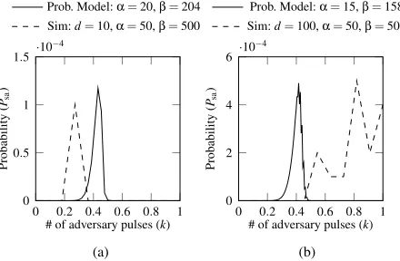
ValidatingPsa.Figure16shows the validation forPsa, at
r=aandPnoise=0.8. Results are shown for differentk, at
distances of 10mand 100m. Each scenario is run 106times,
andPsa is calculated as the proportion of these where the
adversary succeeded to hide the authentic code. Again the results show comparable patterns between the model and simulations. There is a slight horizontal shift atkdue to the abstracted noise. In the simulator,Gis set as in (9), which may be a bit too high or low depending on actual noise patterns. In Fig.16a,Gwas relatively low, causing a drop in the simulated
Psa at smallerkcompared to the model. In Fig.16b,Gwas
relatively high, replicatingPsaat higherk.
Another difference between simulations and the model manifests with increasing the distanced between both de-vices. In practice, in UWB, receivers increase their ability to reconstruct the signals (hence, the SNR) by aggregating over more pulses. We noticed that the model provides such comparable probability patters when we decreaseaandb in the model proportionally with increasingdin simulations. For example in Fig.16bwhered =100m,a andbin the simulator had to be increased from 15 and 158 to 50 and 500 respectively (⇠tripled) to account for the increased distance.
Validating the false positives.We also used simulations to confirm that noise would not be falsely mistaken for au-thentic code upon proper selection ofPnoiseandG. For various
Probabilistic Model Simulation Results (box plots)
0 100
0 1
k Pbb>
b
a
(a) {50,50,1}
0 100
0 1
k Pbb>
b
a
(b) {50,50,2}
0 100
0 0.3
k Pbb>
b
a
(c) {50,50,8}
0 200
0 1
k Pbb>
b
a
(d) {50,150,1}
0 200
0 1
k Pbb>
b
a
(e) {50,150,2}
0 200
0 0.3
k Pbb>
b
a
(f) {50,150,8}
Figure 15: Probability of adversary’s failure calculated using (19), and simulations results validating the probabilistic derivations. Each scenario is run with the {a,b,r} parameters shown in the charts’ individual captions.
0 0.2 0.4 0.6 0.8 1 0
0.5 1 1.5 ·10 4
# of adversary pulses (k)
Probability
(
Psa
)
Prob. Model:a=20,b=204 Sim:d=10,a=50,b=500
(a)
0 0.2 0.4 0.6 0.8 1 0
2 4 6 ·10 4
# of adversary pulses (k)
Probability
(
Psa
)
Prob. Model:a=15,b=158 Sim:d=100,a=50,b=500
(b)
Figure 16: The attack is detected when the aggregate energy is betweengandG, butPbb>bais more thanPnoise. The attack
is also detected when energy aggregate is more thanG;z=5.
Section5.1.4.
In conclusion, the simulated probabilities follow compara-ble patterns with the model, and are in the same range. The model derived herein thus serves as a formal means for evalu-ating the efficacy and suitability of UWB-ED in practice. The results also show that the channel condition, such as path loss, noise, and interference due to multipath components, does not affect the performance and security of the system. An adversary can increase the noise level, which can increase false positives. High false positives may eventually cause DoS (which the adversary can mount anyway by jamming the channel), but the adversary remains unable to enlarge distances.
6 Discussion
Adaptive attacks.An adversary can notice the effect of each of its added pulses on the resultant energy, whether annihi-lated or amplified. It can then adapt its attack strategy by dynamically decidingkbased on the number of pulses it has added/annihilated so far during the transmission. The
adver-sary can then utilize its knowledge ofn,a andbin order to, not only decide the optimal value ofkstatically before the transmission begins, but also adjust their distribution in realtime. This attack does not succeed because the adversary cannot control the resultant pulse phase. Injecting excessive energy in BinbexceedsG; injecting in Binadoes not
guaran-tee annihilation because of the unpredictable phase.
Varying energy levels.To achieve perfect signal annihila-tion, an adversary uses the same amplitude expected at the receiver. Instead of injectingkpulses each with a constant en-ergy of,e.g.,2µW, the adversary can inject one pulse with an energy of,e.g.,2kµW. If allkpulses fell in Binb, the aggregate
energy would be the same as when that single high-energy pulse also falls in Binb. However, intuitively, the adversary
is better off injecting multiple pulses with constant energies for two reasons. First, multiple pulses in Binbhave higher
chances of being selected than a single pulse, thus evading the Robust Code Verification check. Second, for those that fall in Bina, any leftover energy after annihilating a pulse,
regardless of the phase, will be counted towards the overall aggregate, thus hurts the adversary’s cause.
InfluencingG through distance shortening.Instead of enlarging distances directly, the adversary can first mount a distance-reduction attack to trick the devices into using higherG(recall: smaller signal attenuation due to shorter path loss leads to higherGcalibration). It is thus imperative to complement UWB-ED with a distance-reduction detection [5,
6,26]. Devices should alternate between both techniques;
e.g.,if distances ofd1andd2are verified using respectively
UWB-ED and a distance-reduction detection technique, it should be concluded that the actual distance,d, is in the range
d1dd2(d1is a lower bound,d2an upper).
Influencing the number of pulses,n.An adversary can inject a low stream of noise-like energy, not too high to be detected as jamming. However becauseGis set beforehand, it is not influenced by the adversary. By injecting noise, the adversary actually hurts its own cause as it reduces the amount of energy it can use strategically to prevent code detection.
series of physical layer improvements to provide secure and precise ranging [2]. Those include additional coding, pream-bles, and improvement to existing modulations to increase ranging integrity and accuracy. UWB-ED is a potential can-didate for enlargement detection in 802.15.4z. It adheres to the low pulse repetition (LRF) mode frequency (1-2 MHz), works with non-coherent receivers, and supports up to 100m. The 3GPP technical specifications groups are designing the 5G-new radio technology, and it aims to include secure and precise ranging based on wireless signals [16,33]. Proper-ties such as high carrier frequencies, large bandwidths, large antenna arrays, device-to-device communication, and ultra-dense networking will help attain this objective. It is early to say the exact modulation techniques 5G will use for distance measurement, but it is safe to assume that wideband will be used to attain position accuracy; beamforming techniques will achieve long distances. This system is equivalent to setting
r=1 herein without restrictions ona, as transmission power restrictions imposed on UWB do not apply to 5G. However, the security of 5G can be increased further, as it allows for the use of beamforming and coherent receivers.
7 Related Work
Detecting enlargement attacks has lately been a prominent research area. Previous literature explored timing acquisition at the preamble, and data ambiguity at payload. Taponeccoet al.[27] show that the success of enlargement attacks using re-play (or overshadowing) depends on the amount of delay the adversary introduces. Such success is harder for controllable attacks, where the adversary is required to position nodes at specific locations. Compagnoet al.[8] provide a probabilis-tic model for the success of overshadowing attacks, which captures different channel conditions and leading edge detec-tion techniques for ToA estimadetec-tion. None of the above efforts considered adversarial signal annihilation.
Tippenhaueret al.[29] explored a theoretical approach to detect adversarial signal annihilation for distance enlargement: using a single pulse-per-symbol (consecutive integration win-dows represent a symbol). They found that modulation with a 2ns slot size,i.e.,mostly equivalent to a pulse width, might help detect signal annihilation. This, however limits the rang-ing technique to short distances. The effect of multipath on that scheme in practice is also unclear, since reflected signals would directly interfere with authentic ones causing distor-tion (no empty gaps between authentic pulses). In contrast, UWB-ED allows for increased distances by increasing the symbol length, and the sampling time between consecutive pulses is sufficient to handle the multipath effect.
8 Conclusion
We present UWB-ED—the first known technique to detect distance-enlargement attacks against standard UWB ranging systems. UWB-ED is readily deployable for current off-the-shelf receivers, requiring no additional infrastructure. Evalua-tion is performed by deriving the probability of adversarial success in mounting distance enlargement attacks. Results show that the verification code structure herein prevents signal annihilation. The code also allows the use of longer symbol length at the receiver, which is essential to achieve longer distance in the energy constrained UWB system. UWB-ED is thus a good candidate for enlargement detection in practice (e.g.,for 802.15.4z and 5G).
References
[1] 3db. 3db Access AG - 3DB6830 ("proximity based access control"). https://www.3db-access.com/ Product.3.html. [Online; Accessed 22. October 2018].
[2] Task Group 4z. IEEE 802.15 WPAN "enhanced im-pulse radio". http://www.ieee802.org/15/pub/ TG4z.html. [Online; Accessed 22. October 2018].
[3] P. Bahl and V. N. Padmanabhan. RADAR: an in-building RF-based user location and tracking system. InIEEE INFOCOM, volume 2, pages 775–784, 2000.
[4] K. Bauer, D. McCoy, E. Anderson, M. Breitenbach, G. Grudic, D. Grunwald, and D. Sicker. The Directional Attack on Wireless Localization -or- How to Spoof Your Location with a Tin Can. InIEEE GLOBECOM, pages 1–6, 2009.
[5] Ioana Boureanu, Aikaterini Mitrokotsa, and Serge Vau-denay. Towards Secure Distance Bounding. Cryptol-ogy ePrint Archive, Report 2015/208, 2015. https: //eprint.iacr.org/2015/208.
[6] Stefan Brands and David Chaum. Distance-bounding protocols. InEUROCRYPT, pages 344–359. Springer, 1994.
[7] M. Cagalj, S. ˇCapkun, R. Rengaswamy, I. Tsigkogian-nis, M. Srivastava, and J. Hubaux. Integrity (I) codes: message integrity protection and authentication over in-secure channels. InIEEE Symposium on Security and Privacy (S&P), pages 15 pp.–294, 2006.
[9] DecaWave. DecaWave "dw1000 product descrip-tion and applicadescrip-tions". https://www.decawave.com/ products/dw1000. [Online; Accessed 22. October 2018].
[10] D. Dolev and A. Yao. On the security of public key protocols. IEEE Transactions on Information Theory, 29(2):198–208, 1983.
[11] Robert J Fontana and Edward A Richley. Observations on low data rate, short pulse uwb systems. In IEEE International Conference on Ultra-Wideband (ICUWB), pages 334–338, 2007.
[12] Shyamnath Gollakota, Nabeel Ahmed, Nickolai Zel-dovich, and Dina Katabi. Secure in-band wireless pair-ing. InUSENIX Security Symposium, 2011.
[13] Humatics. Time Domain’s PulsON ("p440"). http: //www.timedomain.com/products/pulson-440/. [Online; Accessed 23. October 2017].
[14] Todd E. Humphreys. Assessing the spoofing threat: De-velopment of a portable gps civilian spoofer. InInstitute of Navigation GNSS (ION GNSS), 2008.
[15] Benjamin Kempke, Pat Pannuto, and Prabal Dutta. Sure-Point: Exploiting Ultra Wideband Flooding and Diver-sity to Provide Robust, Scalable, High-Fidelity Indoor Localization. InACM SenSys, pages 318–319, 2016. [16] Xingqin Lin, Jingya Li, Robert Baldemair, Thomas
Cheng, Stefan Parkvall, Daniel Larsson, Havish Koora-paty, Mattias Frenne, Sorour Falahati, Asbjörn Grövlen, and Karl Werner. 5G New Radio: Unveiling the Essen-tials of the Next Generation Wireless Access Technol-ogy, 2018.
[17] A. F. Molisch. Ultrawideband propagation channels-theory, measurement, and modeling. IEEE Transactions on Vehicular Technology, 54(5):1528–1545, 2005. [18] A. F. Molisch, D. Cassioli, C. Chong, S. Emami, A. Fort,
B. Kannan, J. Karedal, J. Kunisch, H. G. Schantz, K. Siwiak, and M. Z. Win. A Comprehensive Stan-dardized Model for Ultrawideband Propagation Chan-nels.IEEE Transactions on Antennas and Propagation, 54(11):3151–3166, 2006.
[19] Andreas F. Molisch.Wireless Communications. Wiley Publishing, 2nd edition, 2011.
[20] Andreas F. Molisch, Kannan Balakrishnan, Chia chin Chong, Shahriar Emami, Andrew Fort, Johan Karedal, Juergen Kunisch, Hans Schantz, Ulrich Schuster, and Kai Siwiak. IEEE 802.15.4a channel model - final re-port. InConverging: Technology, work and learning. Australian Government Printing Service. [Online; Ac-cessed 4. November 2018], 2004.
[21] A. Muqaibel, A. Safaai-Jazi, A. Bayram, and S. M. Riad. Ultra wideband material characterization for in-door propagation. InIEEE Antennas and Propagation Society International Symposium, volume 4, pages 623– 626, 2003.
[22] Pericle Perazzo, Lorenzo Taponecco, Antonio A. D’amico, and Gianluca Dini. Secure Positioning in Wireless Sensor Networks Through Enlargement Mis-control Detection. ACM Transactions on Sensor Net-works, 12(4):27:1–27:32, 2016.
[23] Christina Pöpper, Nils Ole Tippenhauer, Boris Danev, and Srdjan ˇCapkun. Investigation of Signal and Mes-sage Manipulations on the Wireless Channel. In Vijay Atluri and Claudia Diaz, editors,Computer Security – ESORICS 2011, pages 40–59. Springer, 2011.
[24] Swiss Post. Drones as transportation
ve-hicle.
https://www.post.ch/en/about- us/company/media/press-releases/2017/swiss- post-drone-to-fly-laboratory-samples-for-ticino-hospitals, May 2018.
[25] Mary-Ann Russon. Drones to the rescue! http://www. bbc.com/news/business-43906846, May 2018.
[26] Mridula Singh, Patrick Leu, and Srdjan ˇCapkun. UWB with Pulse Reordering: Securing Ranging against Relay and Physical Layer Attacks. InNDSS, 2019.
[27] L. Taponecco, P. Perazzo, A. A. D’Amico, and G. Dini. On the Feasibility of Overshadow Enlargement Attack on IEEE 802.15.4a Distance Bounding. IEEE Commu-nications Letters, 18(2):257–260, 2014.
[28] Nils Ole Tippenhauer, Kasper Bonne Rasmussen, Christina Pöpper, and Srdjan ˇCapkun. Attacks on Public WLAN-based Positioning. InACM/Usenix MobiSys, 2009.
[29] Nils Ole Tippenhauer, Kasper Bonne Rasmussen, and Srdjan ˇCapkun. Physical-layer Integrity for Wireless Messages.Computer Networks, 109(P1):31–38, 2016.
[30] Deepak Vasisht, Swarun Kumar, and Dina Katabi. Decimeter-level localization with a single wifi access point. InUSENIX NSDI, pages 165–178, 2016.
[31] S. ˇCapkun and J. Hubaux. Secure positioning of wireless devices with application to sensor networks. InIEEE Computer and Communications Societies., volume 3, pages 1917–1928, 2005.
[33] Henk Wymeersch, Gonzalo Seco-Granados, Giuseppe Destino, Davide Dardari, and Fredrik Tufvesson. 5G mmWave Positioning for Vehicular Networks. Wireless Communications, 24(6):80–86, 2017.
[34] Paul A Zandbergen. Accuracy of iPhone locations: A Comparison of Assisted GPS, WiFi and Cellular
Posi-tioning. Blackwell Transactions in GIS, 13(s1), 2009.
Errata Slip #5
Proceedings of the 28th USENIX Security Symposium
In the paper “UWB-ED: Distance Enlargement Attack Detection in Ultra-Wideband” by Mridula Singh, Patrick Leu, AbdelRahman Abdou, and Srdjan Capkun, ETH Zurich (Wednesday session, “Wireless Security,” pp. 73–88 of the Proceedings) the authors have provided an acknowledgment:
Acknowledgment