A Study on the Black Start Process of a real Distribution Network
with CHP plants and BESS
Christoph Strunck1,2, Marvin Albrecht1,2, Gerhard Meindl1 and Christian Rehtanz2
1 Es-geht!-Energiesysteme GmbH, 10827 Berlin, Germany
2 TU Dortmund, Institute for Energy Systems, Energy Efficiency and Energy Economics, 44227 Dortmund, Germany
Abstract. The power system experiences many changes, which are leading to new challenges. The electric energy will no longer be generated only by large power plants, but rather by numerous decentralized energy resources that are primarily installed in distribution grids. In particular, power system restoration processes after a blackout will face new challenges. However, new opportunities by the widespread use of renewable energy resources arise. In this paper, the black start capability of a real distribution grid in Germany, operated by SWW Wunsiedel, will be investigated, as it has a high share of decentralised energy resources and a BESS with black start capability. For this purpose, the medium voltage level of the distribution grid is investigated with static load flow simulations to evaluate the best black start strategy. The driving forces of this black start concept are an 8 MW BESS unit and a 13.5 MW CHP plant.
1 Motivation
In conventional power systems, large synchronous generators, connected to the high voltage level, produce electric energy that supplies loads in medium and low voltage levels. In future power systems, the majority of decentralized energy resources (DER) will be installed at the distribution grid, so that bidirectional power flows will occur. This leads to many challenges, such as a reduced system inertia and fluctuating infeed. Nevertheless, many opportunities are given such as an optimized provision of ancillary services by these generation units. [1,2]
In the past, numerous blackouts occurred throughout the world. On September 3rd 2003, a tree flashover on an important transmission line in Switzerland left 56 million people without electricity for several hours. The damage amounted to about 1.2 billion euro. [3] On November 4th 2006, around 15 million people throughout Europe were affected for about 1.5 hours by a power outage starting in Germany [4]. In 2012, a blackout in India left over 620 million people without electricity [5]. In total, the restoration of energy supply took about 10 hours [5]. Especially this example shows, that blackouts can last for a long time before the restoration process is completed. To restore the grid as fast as possible, it is necessary to define efficient restoration schemes. However, many black-start capable conventional power plants will no longer be available in the future. In addition, non-controllable DER, such as PV plants, will have a large impact on the system frequency during the restoration process. If a prespecified frequency is measured by these units, they will reconnect or disconnect automatically. However, besides these challenges, new opportunities arise.
In addition to the conventional top down restoration, with DER bottom up restoration will be possible (cf. Fig. 1). [6] In this paper, the black-start capability of a distribution grid is investigated. For this purpose, a study on a real German distribution network with a high share of renewable energy sources (RES) will be evaluated. The main goal is a fast resupply of the distribution network during a global blackout by only using DERs. Besides a quick power restoration of the costumers and in particular critical infrastructure independently, a black started distribution network offers a meaningful support for the global restoration process (Fig. 1).
Fig. 1.System restoration process: top down & bottom up
This paper is structured as followed. First, the distribution grid of SWW Wunsiedel is introduced. Subsequently, the challenges during a restoration process in a distribution grid are discussed. After the methodology has been explained, simulation results under different strategies and scenarios will be evaluated. The paper closes with a conclusion and outlook.
to
p
d
o
w
n
b
o
tt
o
m
up
+ - +
2
Distribution grid of investigations
In this case study, the SWW Wunsiedel distribution grid has been investigated. It supplies a total of 18,000 customers with a cable length of 170 km in the medium voltage and 260 km in the low voltage grid. Moreover, it is divided in eleven feeders. In 2017, the annual peak load was 14.1 MW.
In general, the grid is meshed. However, due to the high protection requirements of a meshed network, it is not operated as such, but rather as an open ring system. It is possible to control generation plants remotely via ripple control units, which are installed at most RES. This allows the network operator to control the active power of RES to assure a reliable and controllable network operation and restoration.
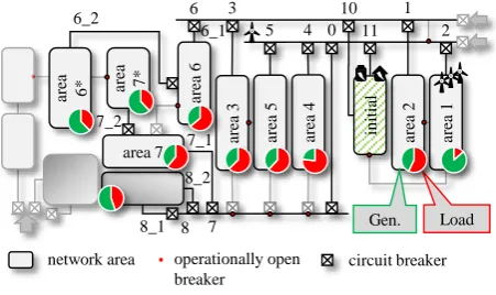
Fig. 2. Schematic plan of the SWW medium voltage grid
SWW's distribution network has a high penetration of renewable energies. A significant part of the installed generation capacity is located in the city centre of Wunsiedel (area 3-5) and the urban areas of 1-2 and 7 (see Fig. 2). Notably, this includes a 13.5 MW combined heat and power (CHP) plant and an 8 MVA battery energy storage system (BESS) displayed with initial. Additionally, a 1.2 MW black start capable CHP plant is connected to the same common point of coupling.
Moreover, four wind power plants with an installed capacity of approximately 10 MWp are located at different connection points in feeder two. Throughout the grid, about 700 PV systems with a maximum peak power of 11 MWp are connected to the low voltage (~95%) and the medium voltage level (~5%). Moreover, almost 93% of the installed PV systems are household systems with less than 50 kWp. The systems are evenly distributed in the grid and present a major challenge for network reconstruction. PV systems are dependent on the weather and therefore already leading to a fluctuating feed-in characteristic during normal operation. As a result, these feed-in deviations influence the network reconstruction negatively since PV plants will account for a considerable proportion of the total feed-in power. Particularly due the automatic disconnection or reconnection of RES in specific frequency ranges, uncontrolled and thus unstable conditions can occur. Especially in case of power system restoration of distribution grids, this can lead to frequency instabilities because of a low system inertia.
3 Study approach for a distribution
system restoration process
In this chapter, an approach for a restoration process in a distribution grid is evaluated. First, the main challenges of a distribution grid restoration process are explained. Next, the methodology for the proposed restoration process will be introduced.
3.1. Challenges of a distribution grid restoration process
The goal for the restoration process of a distribution grid with high penetration of RES and without the overlaying transmission grid connection, is a fast and stable restoration in a minimal amount of time. Hence, public welfare can be assured by supplying food, drinking water as well as the operation of hospitals and nursing homes. However, resupplying industrial customers, before emergency power can no longer be provided, is essential to minimize losses and costs for e.g. production downtime. [7,8]
A main challenge of a restoration process in a distribution network is the low system inertia. Usually, in conventional restoration schemes, large power plants are connected to the grid during the reconstruction. In this case, DER with low inertia or which are completely decoupled via power electronics, will resupply the network. In conventional restoration processes, the system operator can switch the circuit breakers remotely, to reconnect unsupplied areas. In a distribution network, it is not the rule that the switches are remotely controllable. This will challenge the network operator during the reconstruction of his gird.
PV plants and wind turbines are also posing a huge challenge regarding stable grid operation. Wind turbines are highly volatile due to changing wind conditions and can lead to critical frequency deviations and instabilities in small island grids. PV plants are parameterized to connect/disconnect to/from the grid at specific frequencies. [9] Since large oscillations can happen while a feeder is being connected, disconnection of the PV plants can stress the system even more. However, with a suitable control scheme and preliminary studies, RES can be used to stabilize the restoration process as well as supplying the base load. [8]
Hence, the focus of the study regarding the black start process in the SWW distribution grid is mainly on the maximal permissible genset loading for the CHP plant and the resultant frequency deviations for the connection of each feeder while providing a base load of the installed RES. Therefore, an international standard (DIN ISO 8528-5) defines G-classes for CHP plants. Here, for the maximal load increase ±10% of the nominal power Pnom,CHP of the CHP, the frequency deviation may not exceed ∆𝑓 = +10% or ∆𝑓 = −15% , respectively. For
frequency deviations after reconnecting a feeder, the CHP must be able to supply the needed energy as fast as possible to ensure a stable restoration process. [10]
ar
ea 6* area 7*
ar
ea
6
ar
ea
2
in
it
ia
l
ar
ea
4
ar
ea
5
ar
ea
3
area 7 ar
ea
1
circuit breaker network area operationally open
breaker
Gen. Load 1 10 3
6
5 4 0 11 2
7 8 8_1
8_2 7_1 7_2
6_2
3.2. Methodology
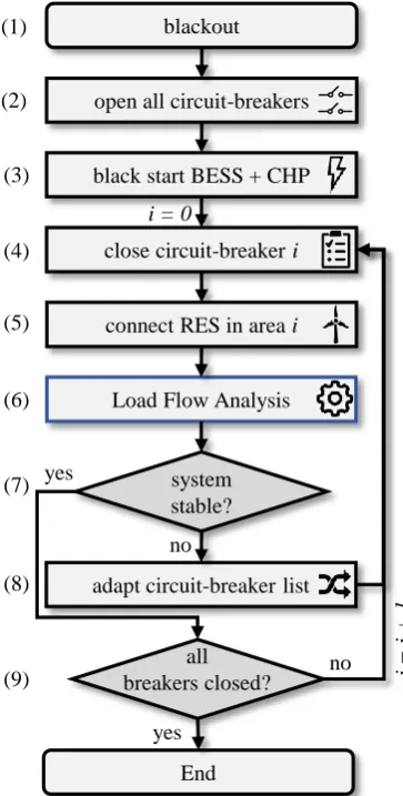
As reflected in section 3.1, the methodology has the goal to provide a planning instrument for finding the best restoration strategy for a distribution grid. Fig. 3 schematically shows the developed approach in detail. First, all circuit breakers that are considered are opened after a blackout occurred (1), (2). In the investigated distribution grid, the CHP plant and the BESS are used to start the grid (3). Hence, in every scenario the starting point will be this entity, assuming that the grid forming inverter of the BESS already black-started the CHP plant. Subsequently, the switchable circuit breakers, with voltage on just one side, are identified and investigated for each step. Successively, these circuit breakers are closed to reconnect an unsupplied area to a supplied feeder (4). Moreover, in a second step, DER in the particular feeder where the voltage is restored, are reconnected to the grid (5). In a repeated load flow calculation (6), the maximum load decrease due to the connected renewables is analyzed, to determine again the influence on the BESS and CHP plant. In case of voltage violations or too high load steps that cannot be intercept by the suppliers, another circuit breaker must be chosen (7).
Fig. 3. Methodology for restoration process of a distribution grid with high penetration of RES
Obviously, this will be pursued until all circuit breakers are closed to supply the grid or limit value violations are
detected (9). Subsequently, for different switching order scenarios, the best restoration process will be chosen.
The goal of this methodology is to identify the best restoration process, based on the load flow results after connecting a feeder to the grid while considering voltage level violations. As stated before, switches in distribution grids often are not capable to be controlled from the distant. Therefore, most of the restoration process time is consumed by driving to the circuit breaker locations to operate the switches. For this purpose, not all switches in the grid are considered, but only the main circuit breakers located at the primary substation, area 6 and area 7 (see Fig. 2) will be used. This will minimize the time to restore the grid. Of course, if there is a feeder in the grid which includes a high amount of load so that instabilities may occur, subordinated switches shall be identified to successively reconnect this area.
4 Simulations and results
To evaluate the proposed scheme, the medium voltage network from SWW Wunsiedel was modelled in DIgSILENT PowerFactory. For the simulation setup, strategies and scenarios are defined to test the robustness of the scheme.
4.1. Strategies and scenarios
Fig. 4. Structure of the simulation setups
To investigate the black start capability of the SWW grid as well as the operation of the distribution grid, different load-in-feed- and weather scenarios are applied as shown in Fig. 4. A strategy describes the sequence in which the circuit breakers are closed. For example, it can be specified whether industries or hospitals are to be supplied first. A scenario is a specification of the consumption and feed-in. Different weather conditions can be specified here. In this study, three main strategies are applied. In the first, customers like industry and critical infrastructure (hospitals, water supply, etc.) are favored, while in the second strategy a base load is established before connecting all feeders. Furthermore, a third strategy with the goal of a stable restoration with respect to the G-classes (DIN ISO 8528-5) of the CHP plant before connecting industry customers at last, is defined [10]. no
open all circuit-breakers
black start BESS + CHP blackout
close circuit-breakeri
End
i =
i +
1
connect RES in area i
Load Flow Analysis
yes i = 0
system stable?
adapt circuit-breaker list yes
no
all breakers closed? (1)
(2)
(3)
(4)
(5)
(6)
(7)
(8)
(9)
scenario 1
strategyi
strategyM strategies
scenarioj
All strategies have in common, that a heavy and a low load scenario is investigated. In this paper, two main strategies with each two scenarios will be shown. Furthermore, for low load, the distinction between with and without wind feed-in is being made to represent different strategies to take wind turbines into account for a black start. Not only are wind turbines often the largest RES in a distribution grid but also a rather volatile generation unit. Hence, wind turbines need to connect to the grid after a stable grid operation is guaranteed. However, a curtailed operation point of wind turbines avoids volatile effects due to changing wind conditions and is gainful to provide secured power. Other than for PV plants, DSOs have the possibility to define the reconnection process in the grid codes or technical requirements for large customers and DERs. However, an assured supply source such as wind power is critical for a stable operation of distribution grids in island grid mode to assure enough flexibility of BESS but also CHP and hydro power plants, which are less volatile.
Moreover, in every case, the restoration process begins at the initial feeder with the CHP plant and the black start capable BESS. With switching the respective circuit breakers, the primary substation is supplied with electricity, which leads to the possibility to connect all feeders connected to this station quickly and without logistical effort. However, due to dynamical effects in the grid, it is crucial to wait until the grid is again in a steady state.
4.2. Simulation results
In the following section, the results for different scenarios and strategies are shown. Fig. 5 shows the results of the load flow calculations after each reconnection step i (compare Fig. 3). Here, the active power of the CHP (blue line) and BESS (yellow line) are displayed for two strategies, a) and b), and two scenarios (solid line and dashed line).
However, in this study it will be assumed, that a proper control scheme that assures the BESS not to be discharged over the allowed limits but rather provide power in a short time frame to relieve the stress on the mechanical parts of the CHP plant. Additionally, the response time to provide the amount of needed power of the BESS may not exceed 500 ms.
Fig. 5 a) shows a strategy, where industry is connected in the second step (i = 2). In the first scenario (Heavy Load) it can be seen, that a high active power step of 𝛥𝑃CHP,step2→3= 3.5 MW arises in i = 3. As stated before,
the G-classes of the CHP plant are the most important constraints and evaluation criteria for a stable and secure grid restoration in this case study. Moreover, the capacity of the BESS should be taken into account as an additional constraint. It is obvious that with the connection of the industry customers in feeder 2 (second breaker) the maximal step size of 𝑃CHP,MaxStep= 10% ∗ 𝑃CHP,norm=
1.35 MW is exceeded with 𝛥𝑃CHP,step2→3= 3.5 MW.
Fig. 5. Simulation results of the load flow calculations: Active power feed-in of the CHP and BESS for two strategies and two scenarios HL (Heavy Load) and LL (Low Load)
However, with an appropriate control scheme of the BESS, where the load increase is balanced in the first seconds and handed over to the CHP plant slowly, this strategy would theoretically be possible to pursue. Nonetheless, the risk of a new blackout would be high. For the connection of the next grid it can be observed, that the load increases linear and does not exceed the maximum power of 𝛥𝑃CHP,MaxStep= 1.35 MW. For
breaker number three to five, more RES than load is connected to the grid. Hence, the BESS is not needed to provide power and the CHP plant is relieved while the maximum load decrease has not been reached. In this case, high load is considered which is mostly influenced by the industry which makes about 1/3 of the total load. Therefore, it is important to investigate this scenario for low load where not only less load but also more RES energy is considered.
Hence, the dashed line in Fig. 5 a) shows the same strategy with low load (LL) and the consideration of wind turbines (+W). The maximal load increase of the CHP plant in this case is 𝛥𝑃𝐶𝐻𝑃,𝑠𝑡𝑒𝑝2→3= 1.5 MW. This corresponds
approximately with the maximal permissible step size of the G3 class that leads to a dynamic frequency deviation of 7.5 Hz for up to three seconds. However, in this
-2 0 2 4 6 8 10
1 2 3 4 5 6 7 8 9 10 11 12 13 14
A
ctiv
e
P
o
w
er
/ MW
breaker number i
CHP (HL) BESS (HL)
CHP (LL+W) BESS (LL+W) a)
-2 0 2 4 6 8 10
1 2 3 4 5 6 7 8 9 10 11 12 13 14
A
ctiv
e
P
o
w
er
/ MW
breaker number i
CHP (HL) BESS (HL)
scenario the influence of the wind is evident since the BESS needs to store energy while five feeders are connected. In theory, that would lead to no or extremely low inertia in the grid or to an operation point of the CHP plant which is not possible. Therefore, the storage ought to store even more energy to guarantee a stable grid operation. Therefore, the storage could be completely charged before discharging again at breaker number eleven. Moreover, due to its geographical proximity sudden changes in wind conditions could quickly lead to a blackout while the wind turbines in feeder 2 provide the majority of the energy. A curtailment of the wind turbines for a secured power is therefore of utmost importance.
For the second strategy with low load, shown in Fig. 5 b), as well as no consideration of wind turbines (LL), the critical feeder 2 is connected in the last switching action. After restoring the complete grid step by step, the CHP plant and the BESS just need to provide approximately 3 MW, because of the high share of RES. The maximum allowed load increase is not reached until the connection of feeder 2 in step i = 13. The load increase at this point is
with 𝛥𝑃𝐶𝐻𝑃,𝑠𝑡𝑒𝑝13→14= 3.9 MW not permissible for the
CHP plant. The heavy load scenario provides almost the same results when connecting feeder 2 (cf. Fig. 5 b) HL). The critical threshold is also exceeded. Even with the appropriate control scheme of the BESS, frequency deviations and the voltage will likely trigger protection devices or damage on electrical equipment in the grid.
In conclusion, also in these strategies it is recommendable to connect feeders with high load, especially with industry customers, gradually to guarantee lower load steps. Knowledge of the emergency power supply of these customers is significant to provide the most economical strategy. Hence, the best connection order can be determined.
5 Conclusion and outlook
In conclusion, the considered distribution grid has the capability to be restored by the combination of CHP und BESS at different load-infeed scenarios. However, some feeders with e.g. high share of large industrial customers need to have a reconnection plan that respects the predicted load as well as the emergency power resources. The simulation results show, that generally a black start process with connecting the whole feeder by switching the few circuit breakers in the grid is possible. However, in feeders with high load further divisions are necessary and recommended. Additionally, in this case study a CHP plant with a large BESS is available. Further strategies with focus on e.g. wind turbines are relevant for other distribution grids.
However, dynamic effects and protection devices, which are not considered in this study, have a significant impact on the restoration process, especially in weak island grids. In particular, the dynamic behavior of synchronous machines and the converter of the BESS as well as the charge/discharge performance. Moreover, as stated before, the connection and disconnection behavior of PV
plant protection schemes is of particular importance for distribution grids during the restoration process or island grid operation. On the other hand, the RES are not providing the maximal possible power in a matter of seconds, but rather of minutes. In Germany, reconnected RES are increasing their power in-feed by 10% PMPP per minute. [9] However, thermal and inductive (motor) loads need high starting currents depending on the temperature and the blackout duration, which is also known as cold load pick up, and stresses the system even more. [11] Hence, these dynamic effects should be considered in future studies.
Different control schemes to include wind turbines and CHP plants in combination with BESS or flywheel storages are also an important task for future investigations. Besides the mentioned consideration of the dynamic behavior, an optimization problem can be formulated to identify the best possible switch order in respect to frequency and voltage deviations as well as critical loads like hospitals and water supply.
References
1. L. Seca, H. Costa, C. L. Moreira, J. A. P. Lopes, An innovative strategy for power system restoration using utility scale wind parks, IREP Symposium Bulk Power System Dynamics and Control, (2013)
2. H. Becker, T. Henning, A. Akbulut, D. Mende, L. Hofmann, Netzwiederaufbaukonzepte: Moegliches Zusammenspiel zwischen Windenergieanlagen und thermischen Kraftwerken, VGB PowerTech, 10, pp. 57-62 (2016)
3. Community Research and Development Information Service (CORDIS): The Cost of Blackouts in Europe, Online, cordis.europa.eu/news/, (2019)
4. Bundesnetzagentur, Report on the disturbance in the German and European power system on the 4th of November 2006, (2007)
5. Central Electricity Regulatory Commission, Report on the Grid Disturbance on 30th of July 2012 and Grid Disturbance on 31th July 2012, (2012)
6. ENTSO-E, Continental Europe Operation Handbook – Policy 5: Emergency Options, Tech. Rep. (2017) 7. C. Steinhart, M. Gratza, K. Schaarschmidt, Local
Island Power Supply with Distributed Generation Systems in Case of Large-Scale Blackouts, (2018) 8. W. Heckmann, et. al., NETZKRAFT
Netz-wiederaufbau unter Berücksichtigung zukünftiger Kraftwerkstrukturen, (2019)
9. VDE Verlag GmbH, Connection and Operation of Power Generating Plants to Low-Voltage Grid (VDE-AR-N 4105), (2018)
10. DIN ISO 8528-5:2018-10, Reciprocating internal combustion engine driven alternating current generating sets - Part 5: Generating sets