Video Compression Using Spatial and
Temporal Redundancy –A Comparative Study
Kusuma.H.R
1, Dr.Mahesh Rao
2P.G Student, Department of Electronics and Communication, MIT Mysore, Karnataka, India1
Professor, Department of Electronics and Communication, MIT Mysore, Karnataka, India2
ABSTRACT: Image compression is required for storing the image or to transmit the image over the wired or wireless
media. A video is nothing but a group of images. Video compression algorithm utilizes numerous standards such as MPEG1, MPEG4 AND H.261, H.264. This study is to look at the existing techniques and to come up with a comparison of these various spatial and temporal redundancy removal techniques used for video compression. With same quality factors such as their Mean Square Error (MSE) and Peak Signal to noise Ratio (PSNR).
KEYWORDS: DCT, DPCM, RLE
I. INTRODUCTION
Digital video coding techniques have been used for a number of years, for example in television broadcasting. However, until recently a number of factors have prevented the widespread use of digital video. An analog video signal typically occupies a bandwidth of few megahertz. However, when it converted into digital form, at an equivalent quality, the digital version typical has a bit rate well over 100 Mbps. This bit rate is too high for most networks or processors to handle. Therefore, digital video information has to be compressed before it can be stored or transmitted.
Video compression is an essential enabler for all digital video applications. Many video codec (compression /decompression) industry standards and so many proprietary algorithms are available to make it practical to store and transmit video in digital form[1]. Many international standards that specialize in different digital video application have been developed. At the same time ,processor technology has improved dramatically in recent years. The availability of cheap, high performance processor together with the development of international standards for video compression has enabled a wide range of video communication applications.
All video coding standards make use of the redundancy intrinsic within digital video information in order to significantly reduce its bit rate. A single frame within a video sequence contains a notable amount of spatial redundancy. Compression standards are designed to eliminate redundancy exist in each frame(image) as well as in video sequence, for this image is first transformed. The transform domain provides a more concise way of representing the visual information. Furthermore, the human visual system is less sensitive to certain (usually high frequency) components of the transformed information. For this reason eliminating this components cannot seriously reducing the visual quality of decoded image. The remaining information can be efficiently encoded using entropy encoding (for example Run length Coding such as Huffman coding)[ref??].
The H.261 standard supports motion video coding for videoconferencing and video telephony applications. It is optimized for video communications at the bit rates supported by ISDNs. Motion Picture Experts group(MPEG) standards addresses the issues of video coding for entertainment and broadcasting purposes. MPEG1 Is optimized for coding of video and for digital storage media such as CD-ROM. The MPEG4 initiative is addressing generic, integrated video communication
II. RELATED WORK
Motion estimation is the process of determining motion vectors that describe the transformation from one 2D image to another, usually from adjacent frames in video sequence [2]. The process of video compression using motion estimation is also known as inter frame coding.
Thazni Aziz, D.Raveena Judie Dolly [3] proposed a Motion Estimation And Motion Compensated Video Compression using DCT And DWT. This process used for the entire motion based video compression with ,motion estimation is the most expensive and time consuming process. Block matching techniques are the most popular and efficient methods for various motion estimation techniques. For the reference frame, a search area is defined for each block in the current frame. The search area is typically sized at 2 to 3 times the macro block size (16×16). Using the fact that the motion between consecutive frames is statistically small, the search range is confined to this area. After the search process, a best match will be found within the area. The best matching usually means having lowest energy in the sum of residual formed by subtracting the candidate block in the search region from the current block located in the current frame. The process of finding best match block by block is called block-based motion estimation. This can be used to find the motion vectors in a current frame[reference [3].
A Motion Compensation
Motion compensation is an algorithmic techniques used to predict a frame in a video, given the previous and/or future frame by accounting for motion of the camera and/or objects in the video. Motion compensation describes a picture in terms of the transformation of a reference picture to the current picture. The reference picture may be previous in time or even from the future. When images can be accurately synthesized from previously transmitted/stored images, the compression efficiency can be improved [4].
Muhammad Aakif Shaikh, Prof. Sagar S Badnekar [5] has proposed a Video Compression Algorithm using Motion Compensation Techniques. Motion compensation is an algorithmic technique employed for the encoding of video data for video compression. Motion compensation describes a frames in terms of the transformation of a reference frame with respect to the current frame. This work deals with the developing efficient video compression approach based on Sum Of Absolute Transformed Difference(SATD) and Absolute Transformed Difference(SAD)method.
Ibrahim Nahhas and Martin Drahansky [6] have proposed a Analysis of Block Matching Algorithms with Fast Computation and Winner-update Strategy. Block matching techniques based on segmentation of the current frame into blocks and the determination of all pixel inside the block having the same displacement vector??. Motion vector are estimated by finding the best –matched counterpart in the previous frame. The block size need to be choosen properly. In general, the smaller the block size, the more accurate, but leading more motion vectors to be estimated and encoded, which means an increase in both computation and overhead information. A block of size 16×16 pixel is considered to be a good choice.
III.METHODOLOGY
Fig-1: Video Codec
A color can be produced by combining the three primary colors red, blue, and green (RGB). The RGB color system is one way of representing color images. Thus with this, the luminance (brightness) and chrominance (color) information can be represented separately. By calculating a weighted sum of the three colors R, G and B we can obtain the luminance signal Y which represent the “brightness” of the color. We can also compute color difference signals Cr, Cb,
and Cg by subtracting the luminance from each primary component using the following.
Cr = Wr *
(R-Y) Cb= Wb*(B-Y)
Cg= Wg*(G-Y)
Where Wr, Wb, and Wg are Weights.
From three color difference signals, only two of them are linearly independent, the third one can always be expressed as a linear combination of the other two. Therefore, we only need the luminance Y and any two of the color difference signals to represent the original color.
The YCbCr representation system has certain advantages over the RGB system. Since the human visual system(HVS) is
less sensitive to chrominance than to brightness, the chrominance signals can therefore be represented with a lower resolution than the luminance without significantly affecting the visual quality. This itself achieves some degree of data compression.
Dividing image into several macro blocks, each macro block has 6 blocks, 4 for Y, 1 for Cb, 1 for Cr.
The discrete cosine transform (DCT) is a popular, fast image coding. For most continuous- tone photographic images, the DCT gives favorable amount of energy compaction. Further, a number of fast algorithms exist for DCT [8].
In general, only few of the DCT coefficients have significant value. Coefficients near to zero value are set to zero. To quantize remaining coefficients, it is divided by the quantizer step size and the result is rounded to the nearest integer. Larger quantizer step size gives higher compression and poorer decoded image quantity. After quantization, nonzero coefficients are further encoded using an entropy coder such as Huffman coder(entropy coding scheme), the most regularly occuring values are represented with shorter codes and the less frequently occuring values with larger codes. Zero coefficients can be efficiently encoded using run-length encoding. The result is a compressed representation of the original image.
To decode the image, the inverse process is carried out. First, the variable-length codes (entropy codes) are decoded to get back the quantized coefficients. These are then multiplied by the appropriate quantizer step size to obtain an approximation to the original DCT coefficients. These coefficients are put through the inverse DCT to get back the pixel values in the spatial domain. These decoded pixel values will not be identical to the original image pixel since a certain amount of information is lost during quantization.
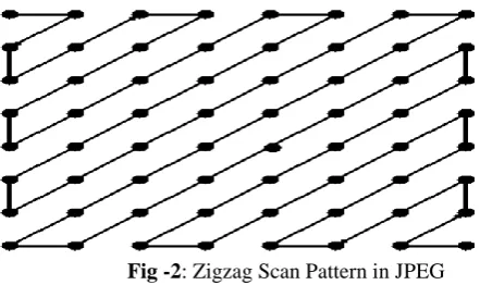
The lower spatial frequency coefficients are more likely to be nonzero than the higher frequency coefficients. For this reason, the quantized coefficients reordered in a zigzag scanning order, starting with the dc coefficient and ending with the highest frequency ac coefficients.
The dc coefficients are coded separately from the ac coefficients. The dc coefficients from adjacent block usually have similar values. Use DPCM to encode the dc value and RLE to encode ac value.
Fig -2: Zigzag Scan Pattern in JPEG
Popular prediction coding is DPCM most video sequences are highly redundant in temporal domain. Within one video sequence, successive frames are usually very similar. Difference in successive frames due to the movement, this movement can often be closely approximated by linear function, example due to a camera pan across the scene.
There are two kind of spatial redundancy: Statistical redundancy and spatial redundancy. Statistical redundancy refers to the fact that the neighboring pixel values in one image are often highly correlated. This redundancy can be removed by using RLE such as Huffman coding. Corresponding decoder used to recover the original image.
Subjective redundancy refer to the fact that human visual system(HVS) is not sensitive to certain components of the visual information. Therefore, such components can be removed without causing severe degradation in subjective quality. By combining these two forms of coding, the capacity required to store or transmit the image can be greatly reduced
IV. COMPARISON OF MPEG-1, MPEG4 AND H.261, H.264 VIDEO CODING
A. MPEG-1
The initial broadcast standard of the MPEG group was the MPEG-1, ISO/IEC 11172, which first parts were released in 1993. MPEG-1 video compression is built on the same technique that is used in JPEG [13]. In add-on to that, it also contains schemes for well-organized coding of a video sequence.
MPEG-1 is paying attention on bit-streams of about 1.5 Mbps and formerly used for storage of digital video on CDs. The meeting point is on compression ratio rather than image quality. It can be considered as conventional VCR quality but digital as a substitute. MPEG-1, the Coding of Moving Pictures and Associated Audio for Digital Storage Media at up to about 1.5 Mbps, is an International Standard 11172, completed in October 1992. International Standard ISO-11172, completed in October 1992. MPEG-1 is proposed mainly for stored interactive video applications (CD-ROM); with MPEG-1, one can store up to 72 minutes of VHS quality (640 x 480 s 30fps) video and audio on a single CD-ROM disk. MPEG-1 can bring full-motion color video at 30 frames per second from CD-CD-ROM. Since audio is generally connected with full motion video, the MPEG standard also concentrate on the compression of the audio information at 64, 96, 128, and 192 kbps [13] and make out the synchronization problem between audio and video by means of time stamps. The first volume attention for MPEG-1 decodes chips (from CCube Microsystems) was a Karaoke entertainment system by JVC [11].
B. MPEG-4
The most significant new features of MPEG-4, ISO/IEC 14496, a propos video compression are the support of even lower bandwidth consuming applications, e.g. mobile entities, and on the additional hand applications by means of tremendously high quality and approximately unlimited bandwidth. The creation of studio movies is one such an example [9]. The majority of the differences between MPEG-2 and MPEG-4 are features not associated to video coding and consequently not associated to surveillance applications MPEG implies completely encoding simply key frames via the JPEG algorithm (described above) and approximating the motion vary between these key frames. Since smallest information is, transmit between every four or five frames, a considerable saving in bits mandatory to describe the image results. As a result, compression ratios above 100:1 [14] are common. The method is asymmetric; the MPEG encoder is extremely complex and places a very serious computational load for motion estimation. Decoding is much easier and can be done by today's desktop CPUs or with low cost decoder chips. MPEG-3 was fused into MPEG-2 and no longer exists. The fundamental method is to predict motion from frame to frame in the temporal direction, and then to use DCT's (discrete cosine transforms) to categorize the redundancy in the spatial directions. The DCT's are done on 8x8 blocks, and the motion prediction is made in the luminance (Y) channel on 16x16 blocks. For a 16x16 block in the present frame being compressed, the encoder looks for a nearest match to that block in a previous or future frame (there are backward prediction modes where later frames are sent first to allow interpolating between frames).
The DCT coefficients (of either the actual data or the difference between this block and the close match) are quantized. A lot of the coefficients end up being zero. The quantization can adopt for each macro block, which is 16x16 of Y and the consequent 8x8's in both U and V. The outcome of all of this, which includes the DCT coefficients, the motion vectors, and the quantization parameters, are Huffman coded using fixed tables. The DCT coefficients have a special Huffman table that is two dimensional that one code state a run-length of zeros and the non-zero value that ended the run. In addition, the motion vectors and the DCT components are DPCM (subtracted from the last one) coded [14].
C H.261
and entropy coding. Although the decoder requires prediction, motion compensation is a choice. Another alternative within the recommendation is loop filtering. The loop filer is applied to the prediction data to reduce. Huge errors when using inter-frame coding. Loop filtering offer a visible improvement in video quality but burden additional processing power. The operation of the decoder allows many H.261-compliant CODECs to afford very different levels of quality at different cost points.
The H.261 standard does not denote a specific adaptive quantization scheme. The H.261 source code operates on non-interlaced pictures occurring 30000/1001 (approximately 29.97) times per second. The tolerance on picture frequency is ± 50 ppm. Pictures are coded as luminance and two color difference components (Y, Cb, and Cr). These components and the codes representing their sampled values are as defined in CCIR Recommendation 601: black = 16, white = 235, zero color difference = 128 and peak color difference = 16 and 240. These values are minimal ones and the coding algorithm works with input values of 1 through to 254. It is necessary to understand the hierarchical structure of video data used by H.261. At the top layer is the image. Every image is divided into groups of blocks (GOBs). Twelve GOBs make up a CIF image; three make up a QCIF image. A GOB correlates to 176 pixels by 48 lines of Y and the spatially equivalent 88 pixels by 24 lines for each chrominance value. Every GOB is divided into 33 macro blocks. A macro block relates to 16 pixels by 16 lines of Y and the spatially corresponding 8 pixels by 8 lines of each chrominance value. Macro blocks are the basic element used for many prediction and motion estimation techniques. When an H.261 manager decides to carry out an intra frame compression or an inter frame compression, or when it segments data as transmitted or non-transmitted, these decisions are made on a block-by-block basis, not on a image-by-image basis [16].
D H.264
H.264 is the product of a mutual project between the ITUT’s Video coding Experts group and the ISO/IEC Moving Picture Experts Group (MPEG). ITU-T is the division with the intention of synchronize Telecommunication standard on behalf of the International Telecommunication Union. ISO stands for International Organization for Standardization and IEC stands for International Electro technical Commission, which manages standards for all electrical, electronic and related technologies [17]. H.264 is the name used by ITU-T, at the same time as ISO/IEC has named it MPEG-4 Part 10/AVC since it is presented as a new part in its MPEG-4 group. The MPEG-4 group contains, for example, MPEG-4 Part 2, which is a standard that has been used by IP-based video encoders and network cameras. Intended to tackle quite a lot of fault in earlier video compression standards, H.264 brings on its goals of supporting:
1) Implementations that deliver an average bit rate reduction of 50%, given a fixed video quality compared with any other video standard.
2) Error robustness so that transmission errors over various networks are tolerated.
3) Low latency capabilities and better quality for higher latency.
4)Straight forward syntax specification that simplifies implementations.
5) Exact match decoding, which defines exactly how numerical calculations are to be made by an encoder and a decoder to avoid errors from accumulating.
The algorithm automatically generates mask image without user interaction that contains only text regions to be inpainted.
V. EXPERIMENTAL RESULTS
This chapter exhibit conduct experiment that were carry out to determine the operation of MPEG-1, MPEG-4 and H.261, H.264.
A Subjective Quality Measurement PSNR
The PSNR block calculates the Peak Signal to Noise Ratio, in decibels, between two images. This ratio is frequently used as a quality measurement between the original and a compressed image. The higher the PSNR, the improved the quality of the compressed or reconstructed image.
The Mean Square Error (MSE) and the Peak Signal to Noise Ratio (PSNR) are the two error metrics used to evaluate image compression quality. The MSE stand for the cumulative squared error between the compressed and the original image, whereas PSNR represents a measure of the peak error. The lesser amount of MSE means the lesser the error [18]. To calculate the PSNR, the block first calculates the mean-squared error using the following equation:
B System Requirement Specification
Original & reconstructed raw files should be in same file format. (E.g. Both files should have .yuv format). Original & reconstructed raw files should have an equal number of frames.
In case, YUV and PCM files do not enclose header information, there is an essential to get necessary information from the user.
It should display output as Frame-by-Frame for video. In case, if data are not equal to frame size or sample Block size, then it discards that frame or block.
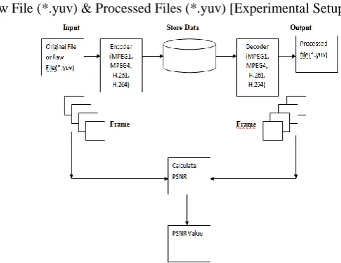
C Process Flow of Raw File (*.yuv) & Processed Files (*.yuv) [Experimental Setup]
Table 5.1 MSE and PSNR values of MPEG1, MPEG4 and H.261, H.264.
Figure (5.1) show the flow chart to compute the PSNR for frame. Input is original raw file in .yuv format. The raw video file encoded using the video encoders such as MPEG1, MPEG4 and H.261, H.264. Encoded data is stored in storage area. The encoded data is decoded using the corresponding decoder. Then calculate the PSNR frame-by-frame, tabulate the PSNR value. Table 5.1 gives the MSE and PSNR values of the international compression standards, MPEG1, MPEG4 and H.261, H.264.
VI. CONCLUSION
In this paper, it has been studied that the existing works on the video compression techniques. Also we have tried to analyze the different video compression techniques with their deliverables MSE and PSNR.
REFERENCES
[1] Suganya.G , Mahesh.K, A Survey: Various Techniques of Video Compression, International Journal of Engineering Trends and technology(IJETT)- Volume7 Number 1- Jan 2014.http://en.m.wikipedia.org/wiki/motion_estimation.
[2] Thazni aziz, D.Raveena Judie Dolly, Motion Estimation and Motion Compensated Video Compression Using DCT And DWT, International Journal of Emerging Technology and Advanced Engineering.http://en.m.wikipedia.org/wiki/Motion_Compensation.
[3] Muhammed Aakif Shaikh, Prof.Sagar S Badnerkar, Video Compression Algorithm Using Motion Compensation Technique, International Journal of Advanced Research in Electronics and Communication Engineering(IJARECE)Volume3,Issue 6,June 2014.
[4] Ibrahim Nahhas and Martin Drahansky, Analysis of Block Matching Algorithm with Fast Computational and Winner-Update Strategies, International Journal of Signal Processing, and Pattern Recognition Vol.6,No.3,June,2013
[5] Deepal Kumar Jain, Devansh Gaur,Kavya Gaur, Neha Jain, Image Compression using Discrete Cosine Transform and Adaptive Huffman Coding, International Journal Of Emerging Trends & Technology in Computer Science.
[6] Ephrainm feig, Fello, IEEE, and Shmuel Winograd, Fellow, IEEE, Fast Algorithm for the Descrete Cosine Transform, IEEE TRANSACTION ON SIGNAL PROCESSING, VOL 40, NO 0, SEPTEMBER 1992.
[7] G.Ramachandran, N.Manikanda Devarajan, T.MuthumanickamS.kannan,C.ArunKumarMadhuvappan, PM Murali ” Comparative study and Implementation of Mixed Level and Mixed Signal Simulation Using PSPICE and VHDL, International Journal of Computational Engineering Research, ISSN:2250-3005,Vol No:2 Pages 218-228.
[8] G.Ramachandran, T.Muthumanickam, N.Manikanda Devarajan , S.kannan,. V.Manikandan, S.Deepika,” Competence to energy consequence with self-power-driven sensor for assessing air parameters” GE-International Journal of Engineering Research, ISSN:2321-1717
[9] T.Sheela, T.Muthumanickam A. Nagappan” A LFSR based Binary Numeral System Using CMOS VLSI” International Journal of VLSI and Embedded Systems, ISSN:2249–6556,Vol 05,Article 12210;January2014