ISSN: 2319-8753
I
nternational
J
ournal of
I
nnovative
R
esearch in
S
cience,
E
ngineering and
T
echnology
(An ISO 3297: 2007 Certified Organization)
Vol. 2, Issue 9, September 2013
Copyright to IJIRSET www.ijirset.com 4977
Modal and Static Structural Analysis of Exhaust
Collector Box for Compressor test facility
Shankar Gouda
1, Praveen M P
2P G student, Department of Mechanical Engineering, EPCET, Bangalore, Karnataka, India1 Asst. Professor, Department of Mechanical Engineering, EPCET, Bangalore,Karnataka, India2
Abstract: Collector box is one of the influencing factors for stability of operation of test compressor
.
Collector box in compressor test facility is used to collect the high pressure exhaust air from the exit of the test compressor. It is subjected to flow fluctuation during compressor testing, making it vulnerable for structural related problems like high vibration. The results indicate that Compressor-Collector box interactions may strongly affect compressor performance unless the lowest resonant frequency of the collector box is much higher than the natural frequency.An analytical and experimental investigation of the static and dynamic behaviour of exhaust Collector box is described, including the effects of compressor-collector box dynamics.
Keywords: Exhaust Collector Box, Axial Compressor test facility.
I. INTRODUCTION
The role of the compressors in a gas turbine is to provide a maximum high pressure air which can be heated in a limited volume of combustion chamber and then expanded through the turbine. The compressor efficiency will determine the power necessary to create the pressure rise of a given air flow and will affect the temperature change which can take place in the chamber.
The compressor test facility is used for following;
For performance evaluation (generating performance characteristics).
For establishing safe operating line.
For validation of numerical tools.
The role of exhaust collector Box is to collect the high pressure exhaust air from the exit of the test compressor to the atmosphere through throttling valves and its associated ducting system. The collector box is designed to give a fairly uniform pressure distribution at the exit of the test compressor and less overall pressure loss.
During the initial test runs on the low pressure compressor, the collector box was found vibrating more. The vibration data collected during test runs showed the frequency component, which is found to be dominating due to resonance.
Resonant vibration is mainly caused by an interaction between the inertial and elastic properties of the materials within a structure. Resonance occurs in a structure whenever the excitation frequency matches with the natural frequency of the structure. Resonance is often the cause of, or at least a contributing factor to many of the vibration and noise related problems that occur in structures and operating machinery.
To understand any structural vibration problem, the resonant frequencies of a structure need to be identified and quantified. Today, modal analysis has become a widespread means of finding the modes of vibration of a machine or structure. In every development of a new or improved mechanical product, structural dynamics testing on product prototypes is used to assess its real dynamic behaviour.
II. GEOMETRICAL CONFIGURATION
ISSN: 2319-8753
I
nternational
J
ournal of
I
nnovative
R
esearch in
S
cience,
E
ngineering and
T
echnology
(An ISO 3297: 2007 Certified Organization)
Vol. 2, Issue 9, September 2013
Copyright to IJIRSET www.ijirset.com 4978
Fig 2.1: Sectional view of Collector Box Fig 2.2: Detailed 2D drawing of exhaust Collector Box
Fig 2.3: CAD Model of exhaust Collector Box
III. MATERIAL SPECIFICATION
The Base material of the Collector Box is Mild Steel [1]. 1. Young’s Modulus, E = 2.10E+11N/m2
2. Poison's Ratio, μ = 0.3
3. Ultimate Strength, бu = 400 Mpa
4. Yield strength, бy = 250 Mpa
IV. LOAD ON THE EXHAUST COLLECTOR BOX
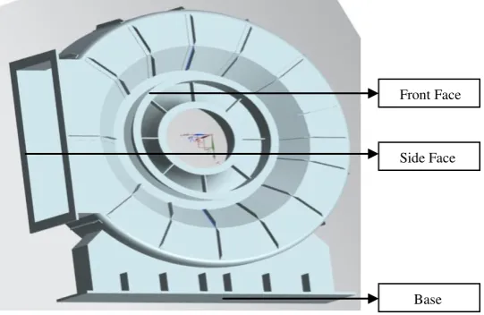
Loading condition is defined to be forces distributed on the inner surfaces of the Collector Box as shown in Fig.4.1. Pressure load of 50.611 kPa is imported from CFD analysis & matched the inner surface of collector box.
Front Face
Side Face
ISSN: 2319-8753
I
nternational
J
ournal of
I
nnovative
R
esearch in
S
cience,
E
ngineering and
T
echnology
(An ISO 3297: 2007 Certified Organization)
Vol. 2, Issue 9, September 2013
Copyright to IJIRSET www.ijirset.com 4979
Fig 4.1: Pressure Load on the Exhaust Collector Box
V. MODAL AND STATIC STRUCTRAL ANALYSIS
A: Introduction to Modal analysis & Static structural analysis:
Modes are inherent properties of a structure, and are determined by the material properties (mass, damping, stiffness) and boundary conditions of the structure. Each mode is defined by a natural (modal or resonant) frequency, modal damping, and a mode shape. If either the material properties or the boundary conditions of a structure change, its modes will change. Modal data are extremely useful information that can assist in the design of almost any structure.
Structural analysis is carried out to determine the effects of loads on physical structures and their components. Structures subjected to this type of analysis includes machinery, buildings, bridges, vehicles, furniture etc..
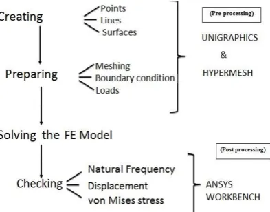
B: The different stages of Modal and static structural analysis:
The software used for the analysis of the Exhaust Collector Box is HYPERMESH & ANSYS WORKBENCH. The stages involved are shown in the figure 5.1.
ISSN: 2319-8753
I
nternational
J
ournal of
I
nnovative
R
esearch in
S
cience,
E
ngineering and
T
echnology
(An ISO 3297: 2007 Certified Organization)
Vol. 2, Issue 9, September 2013
Copyright to IJIRSET www.ijirset.com 4980
VI. FINITE ELEMENT MODEL OF EXHAUST COLLECTOR BOX
All dimensions of the complete assembly of the structure are as per the description provided in the previous section in the problem definition chapter. A finite element model is the complete idealization of the entire structural problem including the node location, the element, physical and material properties, loads and boundary conditions. The purpose the finite element model is to make a model that behaves mathematically as being modelled and creates appropriate input files for the different finite element solvers. The FE model using first order tetrahedral elements for the existing Collector Box is created with the help of HYPERMESH 9.0 as shown in Fig.6.1 & Fig. 6.2 shows tetrahedral element (TET4) geometry.The simplest solid element available to the finite element modeller is the first-order four-node tetrahedron or TET4.
Fig.6.1: Finite element (FE) model of Collector Box Fig.6.2: TET4 Geometry
VII. BOUNDARY CONDITIONS
In this case, Boundary conditions (BC) are applied on the base, side and front faces of the Collector Box as show in the Fig. 7.1, allowing the modal deformation as a whole. Structural boundary conditions are in the form of zero displacements, Boundary conditions specify to act on all directions (X, Y and Z) or in certain directions only.
ISSN: 2319-8753
I
nternational
J
ournal of
I
nnovative
R
esearch in
S
cience,
E
ngineering and
T
echnology
(An ISO 3297: 2007 Certified Organization)
Vol. 2, Issue 9, September 2013
Copyright to IJIRSET www.ijirset.com 4981
VIII. RESULTS AND DISCUSSION
Terminology & Concepts:
• General equation of motion:
• Assume free vibrations and ignore damping:
• Assume harmonic motion ( i.e . )
The roots of this equation are i 2, the eigenvalues, where i ranges from 1 to number of DOF. Corresponding vectors are {u}i, the eigenvectors.
The square roots of the eigenvalues are ωi , the structure’s natural circular frequencies (radians/sec). Natural frequencies
fi are then calculated as fi = ωi /2π (cycles/sec). It is the natural frequencies fi that are input by the user and output by ANSYS.
The eigenvectors {u}i represent the mode shapes - the shape assumed by the structure when vibrating at frequency fi.
Mode Extraction is the term used to describe the calculation of eigenvalues and eigenvectors.
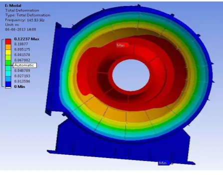
A: Natural Frequencies of exhaust Collector Box without the application of Load:
Fig. 8.1 shows Modal analysis of exhaust collector box. FE analysis is compared with the experimental results (Fig. 8.2) conducted at Compressor Test Rig.
Fig 8.1: Modal Analysis of exhaust Collector Box (No Load)
Table 8.1: Natural Frequencies with respect to Constraints applied on Exhaust Collector Box (without load)
Without Application of load
Constraints Natural Frequency(Hz)
1 2 3
Base Fixed, Side Fixed & Front face with Elastic support 145.83 198.25 234.72
M
u
C
u
K
u
F
t
M
u
K
u
0
K
2M
u
0
)
sin(
t
U
ISSN: 2319-8753
I
nternational
J
ournal of
I
nnovative
R
esearch in
S
cience,
E
ngineering and
T
echnology
(An ISO 3297: 2007 Certified Organization)
Vol. 2, Issue 9, September 2013
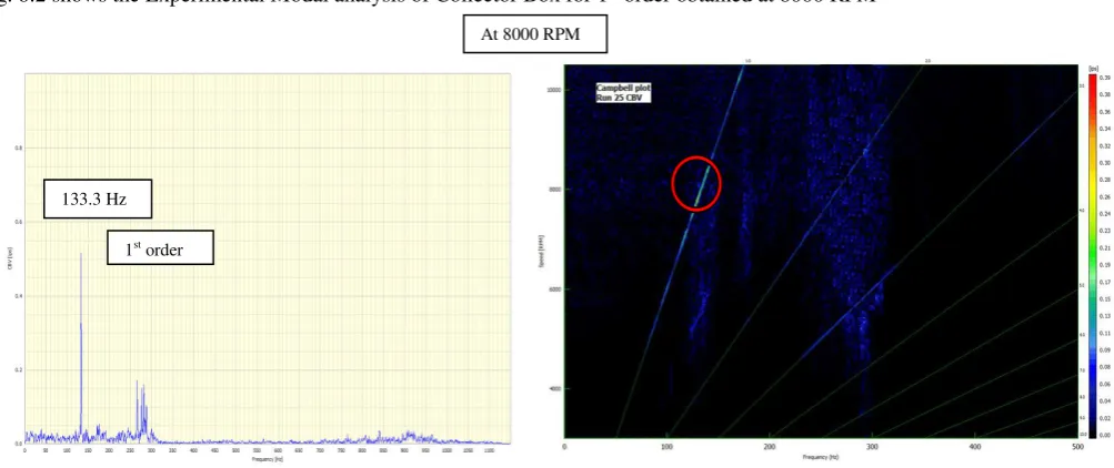
Copyright to IJIRSET www.ijirset.com 4982 Fig. 8.2 shows the Experimental Modal analysis of Collector Box for 1st order obtained at 8000 RPM
Fig.8.2: Experimental Modal Analysis results of existing Collector Box
B: Natural Frequencies of existing Collector Box without the application of Load:
Table 8.2: shows the modal deformation of exhaust Collector Box on application of pressure load of 50.611 kPa.
Table 8.2: Natural Frequencies with respect to Constraints applied on Exhaust Collector Box (with load)
With Application of Load
Constraints Natural Frequency(Hz)
1 2 3
Base Fixed, Side Fixed & Front face with Elastic support 142.54 197.17 232.68
Table 8.3 shows the comparison of 1st Natural frequency of FE model of existing collector box with pressure load, without pressure load and experimental value obtained during compressor test runs.
Table 8.3: Comparison of 1st natural Frequency of FE model with experimental
1st natural frequency (Hz) FE model with Pressure load 142.54 FE model without Pressure load 145.83
Experimental 133.30 Error (without Pressure load) 09.41%
At 8000 RPM
133.3 Hz
ISSN: 2319-8753
I
nternational
J
ournal of
I
nnovative
R
esearch in
S
cience,
E
ngineering and
T
echnology
(An ISO 3297: 2007 Certified Organization)
Vol. 2, Issue 9, September 2013
Copyright to IJIRSET www.ijirset.com 4983 C: Static Structural Deformation on application of Pressure Load for Exhaust Collector Box:
Fig.8: Static Structural Deformation of exhaust Collector Box
Figure 8.3 shows static structural deformation of existing model on application of load. Table 8.4 shows deformation in the direction of applied Load for existing model.
Table 8.4: Static Structural Deformation with respect to Constraints applied on Exhaust Collector Box
Constraints Deformation (mm)
Base Fixed, Side Fixed & Front face with Elastic support 0.529
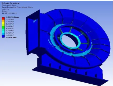
D: von-Mises Stress on application of Load for existing Collector BoxExhaustCollector Box:
Table 8.5 shows the von-Mises Stress distribution for the existing Collector box on application of pressure load. The overall mass and volume of existing Collector Box is 345.86 Kg. Fig.8.4 shows von-Mises stress distribution.
ISSN: 2319-8753
I
nternational
J
ournal of
I
nnovative
R
esearch in
S
cience,
E
ngineering and
T
echnology
(An ISO 3297: 2007 Certified Organization)
Vol. 2, Issue 9, September 2013
Copyright to IJIRSET www.ijirset.com 4984
Table 8.5: von-Mises Stress distribution with respect to Constraints applied on exhaust Collector Box
With Application of load von-Mises stress
Constraints Stress (MPa)
Base Fixed, Side Fixed & Front face with Elastic support 85.5
As the material is ductile, maximum Distortion energy theory (von-Mises theory) is considered for determining the criterion for failure. Taking a factor of safety of 2.0[1], the allowable stress for the material is 200 MPa, based on Yield Stress of 400 MPa. Hence, the design of the Collector Box is considered adequate with a Factor of safety of 8.72.
We know, Factor of Safety = Ultimate Stress / Working Stress
IX. CONCLUSIONS
The investigation on the dynamic behavior of Exhaust Collector box has been successfully executed in this project. Experimental results were used in conjunction with the finite element to predict the dynamic characteristic of Collector box such as the natural frequency and mode shape. Basically, natural frequency and mode shape are important parameters in design. That is because failure can occur if the Collector Box is excited at its natural frequency during operation. The dynamic characteristic such as the natural frequencies and mode shapes of the Collector box was determined numerically. The experimental data was used to validate a finite element model representing the real structure. The FE model presented an average of 10% higher frequencies than the real Structure.
REFERENCES
[1] S.S. Bhavikatti, “Strength of Materials”, 1996.
[2] H Cohen, GFC Rogers, HIH Saravanamuttoo, “Gas Turbine Theory” 4th Edition.
[3] Sweet L M., Richardson H., Wormley D N.," Plenum Air Cushion/Compressor-Duct Dynamic Interactions", Journal of Dynamic systems, Measurements & Control, Vol. 97, Sep. 1975, Pages 283-292.
[4] E.M. Greitzer, “Surge and rotating stall in axial flow compressors, Part I: Theoretical compression system model”, Journal of Engineering for Power, April
1976, Pages 190-198.
[5] E.M. Greitzer and F.K. Moore, “A theory of post-stall transients in axial compressor systems: Part II-Application”, Journal of Engineering for Gas turbines and Power, 1986, Pages 231-239.
BIOGRAPHY
Mr. Shankar Gouda obtained his B.E Mech from Siddaganga Institute of Technology, Tumkur in 2005 and is PG student (M Tech in Product Design & Manufacturing) at East Point College of Engineering & Technology, Bangalore.