Locating Fault with Alarm Correlation Using
Link Failure Detection Algorithm in Optical
WDM Networks
K.Pandiammal
1, S. Arulselvi*
2Assistant Professor, Dept. of ECE, Jerusalem College of Engineering,Chennai, Tamil Nadu, India1
Assistant Professor, Dept. of ECE, Bharath University, Chennai, Tamil Nadu, India2
*
Corresponding Author
ABSTRACT: For several high speed networks, providing resilience against failures is an essential requirement. The main feature for designing next generation optical networks is protecting and restoring high capacity WDM networks from the failures. Quick detection, identification and restoration make networks more strong and consistent even though the failures cannot be avoided. Hence, it is necessary to develop fast, efficient and dependable fault localization or detection mechanisms. In this paper we propose a new fault localization algorithm for WDM networks which can identify the location of a failure on a failed lightpath. Our algorithm detects the failed connection and then attempts to reroute data stream through an alternate path. In addition to this, we develop an algorithm to analyze the information of the alarms generated by the components of an optical network, in the presence of a fault. It uses the alarm correlation in order to reduce the list of suspected components shown to the network operators. By our simulation results, we show that our proposed algorithms achieve less blocking probability and delay while getting higher throughput.
KEYWORDS: Alarm Correlation, blocking probability, delay, Fault Localization, WDM Networks.
I. INTRODUCTION
A. Wavelength-Division-Multiplexing (WDM) Networks
WAVELENGTH division multiplexing (WDM) is the concurrent transmission of multiple streams of data with the help of the special properties of fiber optics [1]. The ability of transferring huge amount of data at high speeds by the users over large distances is offered by the WDM networks. WDM is considered as the most talented technology for the backbone of future next generation internet [2]. In WDM all optical networks, data is routed through optical channels called light paths. Without the wavelength conversion ability, the light path establishment requires same wavelength to be utilized along the entire route of the light path which is commonly referred to the wavelength continuity constraint. WDM enables the employment of a substantial portion of the available fiber bandwidth by allowing many independent signals with different wavelength to be transmitted simultaneously on one fiber [3]. The routing and detection of these signals can be obtained independently since the wavelength estimates the communication path by acting as the signature address of the origin, destination or routing. Hence, the wavelength selective components are necessary for allowing the transmission, recovery or routing of specific wavelengths.
B. Fault Detection and Localization
Fault localization in general network has been studied exclusively for many years in various areas and thus it is not a new problem. It has been studied in the areas like power distribution systems, electrical circuits, industrial control systems, and in communication networks. On the other hand, due to the lack of electrical terminations or the excessive cost and the difficulty in implementation, the existing fault localization schemes for traditional networks cannot be applied to the WDM networks directly [5]. In all optical WDM networks, the network edge routers may be able to detect the existence of a fault whenever a link is damaged or a channel is disconnected. But it is not possible to indicate the exact location of the fault. At this time, no advanced optical technique is introduced.
C. Fault Tolerant in WDM Networks
Failures in WDM networks may seriously damage the end user applications because each lightpath can carry a large amount of traffic. Failures in all optical WDM networks can be classified into two categories according to the scale of their effect [6]. The first one is the wavelength level failure which affects the quality of transmission of each individual lightpath .The second one is the fiber level failure which affects all the lightpath on an individual fiber. Failures can lead to a severe data loss because each lightpath is estimated to operate at a rate of several gigabytes per second [7]. The capability of the network to endure the failures is known as fault tolerance. Due to the node failure or link failure, failure arises. When a link tends to fail, then all its constituent fibers also fails. Each and every connection which utilizes these fibers is rerouted and a wavelength will be assigned. Primary path is a light path which carries traffic during normal operation [18]. In case of a failure, the traffic is rerouted. The large amount of traffic on these networks against the traditional copper links makes the fault tolerance as a major issue.
In this paper we propose a new fault localization scheme, which functions in the WDM layer. In this work, we propose a new algorithm which can identify the location of a failure on a failed lightpath. In addition to this, we develop an algorithm to analyze the information of the alarms emitted by the components of an optical network, in the presence of a fault [8-9].
II. PROPOSED FAULT LOCALIZATION AND ALARM CORRELATION
A. Detection and Localization Algorithm
In this section, we propose a Link Failure Detection Algorithm which can identify the location of a failure on a lightpath. Our proposed algorithm detects the failed connections and tries to reroute data stream through an alternate path. Because of the short interval time of establishing a lightpath, we assume that a failure occurs during data transfer. This shows that the destination node knows the source node and the setup route before an interruption occurs [16-17]. When the destination does not receive expected data stream for the given time interval, then the connection gets interrupted. Immediately, our algorithm will be activated by the destination. The operation of our algorithm is given below.
Fig1 Functions of Link Failure Detection Algorithm
1) Algorithm
Let n1,n2,… ,nk be the set of nodes along the route from the source n1 to the destination nk . 1. The source n1send data packets in fixed time intervals δ. Source sends packets
p1, p2 ,., pk at time t1, t1+δ,,.., t + kδ.
2. The destination nk checks the packet sequence numbers s1, s2 ,…, sk of the packets.
3. When a k / 2 number of consecutive packets are missed within a given time threshold t , the destination detects a fault on the light path.
4. If nk not received the data within the time Interval t , then
4.1 nk raises LFA and transmit backwards to n j ,where j = k −1 4.2 If n j received the data before t , then
4.2.1 It send a REP packet to ni , where i = j +1.
4.2.2 The ni starts a recovery scheme for restoration
4.2.3 n j information is flooded through the network. 4.3 Else
4.3.1 j = j −1
4.3.2 Repeat the step 1.2 4.4 End If
5. End If
Fig. 1 shows the functions of our link failure detection algorithm. As shown in the figure, the alarming signal Link Failure Alarm (LFA) is sent back towards the source till it reaches the first recipient of data and it returns the REPLY (REP) signal is returned to the sender. In response, the RFTR scheme [14] is activated to avoid the failed link and restore the connection through a backup path.
B. Alarm Correlation
The components able to send alarm can be divided in the following groups: • A1 – When the damaged component send alarm;
• A2 – When the component alarms informing that other component is not working correctly.
1) Alarm Correlation Algorithm
When a fault occurs, in order to identify which network component is damaged and which node it belongs each network component has a unique identification. In the network model used here, this identification is composed by a string of four fields
( f 1, f 2, f 3, f 4) having the following meaning for a local node:
f1: It can assume the following values: 0 – non alarming component; 1 – Self alarmed; 2 – Out-alarmed; 3 – Failure masking.
f 2 : It indicates the node number.
f 4 : It identifies the position of the component inside the node. The value of this field varies according to the component: LAP = 0 (Local Access Port);ADF =1or 2 ; RX =1or 2 ; 3R amplifier = 4 or 5 ; TX = 5 or 6 ;PS = 3 .
Algorithm
At the physical route domain, all network components that belong to any channel are numbered as C1,C2,..and associated to each one of the alarm components of the respective alarms that will be sent to the network management server (NMS) if they fail.
Let S1 denote the suspected list of components.
1. Server receives alarma from the component Ci . 2. If a = A1 then
2. 1 Add Ci (a) to S1 3. Else If a = A2 then 3.1 For each channelCHi
3.1.1 Add C1(a) to S1 . 3.2 For each component Ck (a), k ≠ 1
3.2.1 If ADk = PD(i), thenwhere ADk is alarmdomain and PD is the route domain, 3.2.1.1 Add Ck (a) to S1.
3.2.2 Else
3.2.2.1 Drop the alarma 3.2.3 End If
3.3 End For 4. End If
II. SIMULATION RESULTS
A. Simulation Model and Parameters
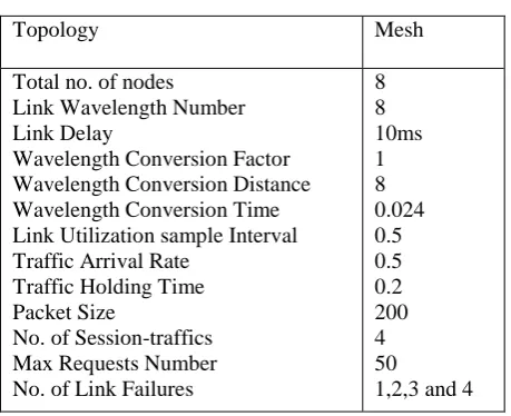
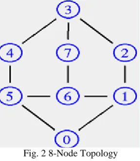
In this section, we examine the performance of our Fault Localization and Alarm Correlation algorithm (FLAC) with an extensive simulation study based upon the ns-2 network simulator [15]. We use the Optical WDM network simulator (OWNs) patch in ns2, to simulate an 8-Node topology (Fig.3). Various simulation parameters are given in table I.
TABLE I
SIMULATION PARAMETERS
Topology Mesh
Total no. of nodes Link Wavelength Number Link Delay
Wavelength Conversion Factor Wavelength Conversion Distance Wavelength Conversion Time Link Utilization sample Interval Traffic Arrival Rate
Traffic Holding Time Packet Size
No. of Session-traffics Max Requests Number No. of Link Failures
8 8 10ms 1 8 0.024 0.5 0.5 0.2 200 4 50
1,2,3 and 4
In our experiments, we will consider multiple link failures. We vary the number of link failures as 1, 2, 3 and 4. The connection requests are distributed randomly on all the network nodes. In all the experiments, we compare the results of FLAC with End-to-End [5] scheme.
Fig. 2 8-Node Topology
B. Performance Metrics
In our experiment, we measure the blocking probability, end-to-end delay and throughput.
Blocking Probability: It is the ratio of number of rejected requests to the total number of requests sent.
Average end-to-end delay: The end-to-end-delay is averaged over all surviving data packets from the sources to the
destinations.
Throughput: It is the number of packets received successfully.
Channel Utilization: It is the ratio of bandwidth received into total available bandwidth for a traffic flow.
C. Results
Our simulation results for the number of failures are presented in Table II. TABLE II SIMULATION RESULTS No of failur es Blocking Probability
Delay Throughput
FLA C End- To-End FLA C End -To-End FLA C End- To-End 1 0.54
32 0.686 67 1.09 66 2.32 457
732 427
2 0.61 78 0.716 66 1.73 54 3.09 908
642 281
3 0.68 05 0.785 74 2.25 53 4.72 548
564 152
4 0.74 16 0.823 66 4.48 25 6.57 268
405 104
Our simulation results for the various rates are presented in Table III.
TABLE III SIMULATION RESULTS
FLAC End-To- End
FLAC End-To- End
FLAC End-To- End
2 0.01 0.15 200.8101 258.462486 0.034098 0.015658 4 0.122075 0.2093846 165.6041 243.106743 0.030568 0.01366 6 0.304862 0.4923077 101.2084 230.450229 0.024459 0.006868 8 0.507692 0.6967554 59.88886 152.666943 0.017623 0.002062
A. Based on Failures
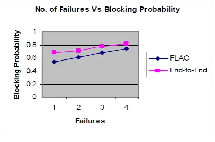
In the initial experiment, we vary the number of failures as1, 2, 3 & 4 and measure the blocking probability, end-to-end delay and Throughput [12-13].
Fig. 3 No. of Failures Vs Blocking Probability
Fig.3 shows the blocking probability obtained with our FLAC algorithm compared with End-to-End scheme. It shows that the blocking probability is significantly less than the End to- End, when number of failures increases.
Fig. 4 No. of Failures Vs Delay
Fig. 5 No. of Failures Vs Throughput
Fig. 5 shows the throughput occurred for various failures. As we can see from the figure, the through put is more in the case of FLAC when compared to End-to-End scheme.
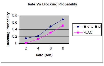
B. Based on Rate
In the next experiment, we vary the traffic rate as 2Mb, 4Mb….8Mb and measure the blocking probability, end-to-end delay and channel utilization.
Fig. 6 Rate Vs Blocking Probability
Fig.6 shows the blocking probability obtained with our FLAC algorithm compared with End-to-End scheme. It shows that the blocking probability is significantly less than the DPBR, as rate increases.
Fig.7 shows the end-to-end delay occurred for various rates. It shows that the delay of FLAC is significantly less than the End-to-End scheme.
Fig.8 shows the channel utilization obtained for various rate. It shows that FLAC has better utilization than the End-to-End scheme.
V. CONCLUSION
Quick detection, identification and restoration make networks more strong and consistent even though the failures cannot be avoided. Hence, it is necessary to develop fast, efficient and dependable fault localization or detection mechanisms. In this paper we have proposed a new fault localization algorithm for WDM networks which can identify the location of a failure on a failed lightpath. Our algorithm detects the failed connection and then attempts to reroute data stream through an alternate path. We have assumed that a failure happens during the data transfer mode due to the short interval time of establishing a lightpath. This implies that the destination node is aware of the source node and the setup route before an interruption of service occurs. The algorithm will be activated once a connection is disrupted. This happens when the destination does not receive expected data stream any longer. In addition to this, we have developed an algorithm to analyze the information of the alarms generated by the components of an optical network, in the presence of a fault. The algorithm proposed uses the alarm correlation in order to reduce the list of suspected components shown to the network operators. By our simulation results, we have shown that our proposed algorithms achieve less blocking probability and delay while getting higher throughput.
REFERENCES
[1] Canhui (Sam) Ou Hui Zang ,Narendra K. Singhal, Keyao Zhu, Laxman H. Sahasrabuddhe, Robert A. Macdonald, And Biswanath Mukherjee, “Sub path Protection For Scalability And Fast Recovery In Optical WDM Mesh Networks”, IEEE Journal On Selected Areas In Communications, Vol. 22, No. 9, November 2004.
[2] Menon R., Kiran C.M., "Concomitant presentation of alopecia areata in siblings: A rare occurrence", International Journal of Trichology, ISSN : 0974-7753, 4(2) (2012) pp.86-88.
[3] Vinh Trong Le, Son Hong Ngo, Xiao Hong Jiang, Susumu Horiguchi and Yasushi Inoguchi, “A Hybrid Algorithm for Dynamic Lightpath Protection in Survivable WDM Optical Networks”, IEEE, 2005
[4] Sateesh Chandra Shekhar, “Survivable Multicasting in WDM Optical Networks”, August, 2004.
[5] Jeyanthi Rebecca L., Dhanalakshmi V., Sharmila S., "Effect of the extract of Ulva sp on pathogenic microorganisms", Journal of Chemical and Pharmaceutical Research, ISSN : 0975 – 7384 , 4(11) (2012) pp.4875-4878.
[6] Bin Wu, Pin-Han Ho and Kwan L. Yeung, “Monitoring Trail: a New Paradiagm for Fast Link Failure Localization in WDM Mesh Networks”,
IEEE Global Telecommunications Conference, 2008, IEEE GLOBECOM 2008.
[7] Sharmila S., Rebecca L.J., Saduzzaman M., "Effect of plant extracts on the treatment of paint industry effluent", International Journal of Pharma and Bio Sciences, ISSN : 0975-6299, 4(3) (2013) pp.B678-B686.
[8] Hongqing Zeng, Alex Vukovic, and Changcheng Huang, “A novel end to- end fault detection and localization protocol for wavelength-routed WDM networks”, Submitted in the Communications Research Centre Canada.
[9] S.Ramamurthy, Laxman Sahasrabuddhe, and Biswanath Mukherjee, "Survivable WDM Mesh Networks", Journal of light wave technology,
[10] Shanthi B., Revathy C., Devi A.J.M., Subhashree, "Effect of iron deficiency on glycation of haemoglobin in nondiabetics", Journal of Clinical and Diagnostic Research, ISSN : 0973 - 709X, 7(1) (2013) pp.15-17.
[11] Michael T. Frederick and Arun K. Somani, “A single-fault recovery strategy for optical Networks using sub graph routing”, The International Journal of Computer and TelecommunicationsNetworking, Volume 50, Issue 2 (February 2006)
[12] MurielM´edard, “Network Reliability and Fault Tolerance”, IEEE Transactions on Volume 50, Issue 1, Page(s):85 – 91, Mar 2001
[13] Hongsik Choi, Suresh Subramaniam, and Hyeong-Ah Choi, “On Double-Link Failure Recovery in WDM Optical Networks”, INFOCOM
Volume: 2, on page(s): 808- 816 vol.2, 2002
[14] Rayen R., Hariharan V.S., Elavazhagan N., Kamalendran N., Varadarajan R., "Dental management of hemophiliac child under general anesthesia", Journal of Indian Society of Pedodontics and Preventive Dentistry, ISSN : 0970-4388, 29(1) (2011) pp.74-7
[15] Yufeng Xin, Jing Teng, Gigi Karmous-Edwards, George N. Rouskas and Daniel Stevenson, “Fault Management with Fast Restoration for Optical Burst Switched Networks”, IEEE, 2004.
[16] Jian Wang,Laxman Sahasrabuddhe and Biswanath Mukherjee, “Fault Monitoring and Restoration in Optical WDM Networks”, National Fiber Optic Engineers Conference NFOEC 2002.
[17] Joon-Young Kim, Sil-Gu Mun, Ju-Hee Park, Jin-Serk Baik and Chang- Hee Lee, “Protection and Fault Localization in a WDM-PON”, Korea Advanced Institute of Science and Technology.
[18] Hongqing Zeng, Alex Vukovica, Changcheng Huangb, Heng Huaa and Michel Savoiea, “Wavelength-routing fault detection in an AON testbed utilizing concatenated pilot tones”, Submitted in the Communications Research Centre Canada.
[19] G.Ramesh and S.Sundara Vadivelu, “A Reliable and Fault-Tolerant Routing for Optical WDM Networks”, International Journal of Computer Science and Information Security, December – 2009.
[20] B Karthik, TVUK Kumar, Noise Removal Using Mixtures of Projected Gaussian Scale Mixtures, World Applied Sciences Journal, 29(8), pp 1039-1045, 2014.
[21] Daimiwal, Nivedita; Sundhararajan, M; Shriram, Revati; , Non Invasive FNIR and FMRI system for Brain Mapping . [22] Daimiwal, Nivedita; Sundhararajan, M; , Functional MRI Study for Eye Blinking and Finger Tapping.
[23] Shriram, Revati; Sundhararajan, M; Daimiwal, Nivedita; , Effect of change in intensity of infrared LED on a photoplethysmogramIEEE Communications and Signal Processing (ICCSP), 2014 International Conference on, PP 1064-1067,2014.
[24] Kanniga, E; Srikanth, SMK; Sundhararajan, M; , Optimization Solution of Equal Dimension Boxes in Container Loading Problem using a Permutation Block AlgorithmIndian Journal of Science and Technology, V-7, I-S5,PP 22-26, 2014.