AN IMPROVED METHOD FOR MICROWAVE
NONDESTRUCTIVE DIELECTRIC MEASUREMENT OF LAYERED MEDIA
H. Zhang, S. Y. Tan, and H. S. Tan
School of Electrical and Electronic Engineering Nanyang Technological University, Singapore Singapore 639798
Abstract—This paper presents an improved method for microwave nondestructive dielectric measurement of layered media using a parallel-plate waveguide probe. The method bases on measuring the
S parameterS11 or reflection coefficient from the N-layer media over the range of 1 to 10 GHz. Formulation for the aperture admittance is presented which allows the solving of the inverse problem of extracting the complex permittivity for two cases of the media, (1) one that terminates into an infinite half-space, (2) one that terminates into a sheet conductor. Our theoretical analysis allows the study of the effects of air gaps and slab thickness on the probe measurements. Through numerical simulations, the ability to use the proposed method for dielectric spectroscopy and thickness evaluation of layered media is demonstrated.
1. INTRODUCTION
Different measurement techniques have been developed to measure dielectric properties. Most commonly, the dielectric properties of the materials are derived from admittance measurement. Many factors have to be considered when choosing the appropriate technique to obtain the desired information on the dielectric properties. Some of these factors include the frequency range, required measurement accuracy, sample size, surface topology, state of the material (liquid, solid, powder, and so forth), destructive or nondestructive, and contacting or non-contacting. In applications such as biomedical microwave diagnostics where it is not permissible to destroy any part of the material under test (MUT), the solutions to nondestructive dielectric measurement restrict to a few. However the currently available techniques have their limitations in terms of bandwidth, accuracy, sample size, etc. Therefore there is a need for a newreliable device for dielectric measurements.
Intensive studies have been done in the area of high frequency measurement of the complex permittivity of dielectric materials. The basic principles of operation include transmission line and cavity resonance [19, 20]. Transmission techniques are attractive for measurements over a very wide swept of frequencies. On the other hand cavity resonant techniques are limited to only one or a few frequencies, defined by the cavity dimensions. Furthermore, these techniques are destructive. The solutions to nondestructive dielectric measurements of material at high frequency are thus limited to transmission techniques using open-ended coaxial (OEC) probe [21– 24], open-ended rectangular waveguide [25–28] and free-space method [29]. The latter two present frequency limitations that affect the size of the MUT to be used. Hence the most widely used technique in dielectric spectroscopy is using the OEC probe due to its simplicity and accuracy in broadband nondestructive measurements. However the OEC probe is recommended for measuring liquids and semi-solids [23, 30–32].
In this paper, we propose an improved method for dielectric measurements of an N-layer dielectric material at microwave frequencies using a parallel-plate waveguide probe. This device has been used previously for microwave detection of breast cancer [33]. Similar to [33], the method derives information from S11 measurements. S11 or reflection coefficient from the MUT translated to the admittance at the aperture of the parallel-plate waveguide probe allows the inverse problem of obtaining the complex permittivity of the MUT to be solved.
radiating into a layered dielectric terminated by an infinite half-space; and terminated by a conducting sheet, developed using a method employing mode matching technique with Fourier transform. Subsequently in Section 3, numerical results are presented to illustrate the effectiveness of this method. Also the effects of air gap and slab thickness on the probe measurement are analyzed in the same section. Finally, the conclusions are summarized in Section 4.
2. APERTURE ADMITTANCE OF THE PARALLEL-PLATE WAVEGUIDE PROBE
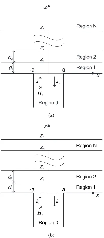
The probe to be used as the dielectric measurement device is essentially a transverse electric and magnetic (TEM) mode-excited, parallel-plate waveguide opening onto a ground plane as depicted in Fig. 1. The aperture is in the xy plane, positioned at z = 0. Evanescent TM0n modes are assumed to co-exist near the probe end. Due to the symmetry of the problem, TE modes may be neglected. To simplify analysis, we consider the probe of width 2ais infinite in extent in the
y-axis, with flanges infinite in extent in both the x- andy-axes. The flanged probe acts as the microwave source radiating into the layered dielectric MUT. Each layer of the dielectric material is assumed to be homogeneous and isotropic, with a relative complex permittivity ofεr=εr−jεr. The radiation fields into a stratified dielectric from this flanged guide have been suggested in [33, 34]. We extend and apply this theory to our method of nondestructive dielectric measurement of an
N-layer stratified dielectric slab, backed and unbacked by a conducting sheet. The time harmonic variation ofejωtis assumed and suppressed throughout the paper.
2.1. Termination by an Infinite Half Space
Consider the parallel-plate waveguide probe radiating in the N-layer dielectric MUT (see Fig. 1). The Nth layer is unbounded in the z -direction (Region N is an infinite dielectric half space). The incident and reflected magnetic fields inside the parallel-plate waveguide are given respectively as
Hyi(x, z) = H0Ie−jkcz (1)
Hyr(x, z) =
∞
m=0
cmcosam(x+a)ejξmz (2)
where
ξm =
k2
i
k kr
i
H
(a)
a -a
Region 0
Region 1
i k 1
Region 2
r k
i
H 2
Region N
2
1 N-1 N
(b)
am =
mπ
2a (4)
and H0I is the amplitude of the incident magnetic field with wavenumberkc in the guide (Region 0).
The transmitted field outside the probe unbounded in RegionN
in the spectral domainζ can be represented as
HyN(x, z) = 1 2π
∞
−∞
˜
HN+(ζ)ejζx−jkzNzdζ (5)
where
kzN =
k2
N −ζ2 (6)
˜
HN+(ζ)e−jkzNzN and HN
y (x, zN) are Fourier transform pair. In the bounded Regionn, 1≤n≤N−1, the field is
Hyn(x, z) = 1 2π ∞ −∞ ˜
Hn+(ζ)e−jkznz+ ˜H−
n(ζ)ejkznz
ejζxdζ (7)
where
kzn =
k2
n−ζ2 (8)
kN and kn are the wavenumbers in the Regions N and nrespectively. The boundary conditions require tangential E field continuity in thex-direction and tangentialH field continuity atzn=
n
i=1di, 1≤
n≤N−1, that is
˜
Exn(ζ, z=zn) = ˜Exn+1(ζ, z =zn) ˜
Hyn(ζ, z=zn) = ˜Hyn+1(ζ, z =zn) (9) ˜
ExN(ζ, z =zN) = 0
Conforming tangential E field boundary condition at the aperture (−a < x < a, z= 0) yields
˜
H1+(ζ) =
1 1−α1(ζ)
ε1
εc
H0Iξ0K0(ζ)−
∞
m=0
cmξmKm(ζ)
(10)
where
α1(ζ) = ˜
H1−(ζ) ˜
H1+(ζ) (11)
Km(ζ) =
jζ kz1(ζ2−a2m)
Subsequently enforcing boundary conditions for each layer leads to recurrence relations as given below
αn= ˜
Hn−(ζ) ˜
Hn+(ζ) =
1−βnγn+1 1 +βnγn+1
e−j2kznzn (13)
where
βn=
εrnkzn+1 εrn+1kzn
(14)
and
γn+1 =
1−αn+1ej2kzn+1zn
1 +αn+1ej2kzn+1zn
. (15)
As a consequence, the tangential H field continuity in the aperture plane yields
H0I+
∞
m=0
cmcosam(x+a) = 1 2π ∞ −∞ ˜
H1+(ζ)(1 +α1)ejζxdζ
= 1 2π ∞ −∞
1 +α1 1−α1
ε1
εc
H0Iξ0K0(ζ)−
∞
m=0
cmξmKm(ζ)
ejζxdζ. (16)
Multiplying (16) by cosan(x + a) and integrating both sides with respect tox from−atoa, one obtains
ε1
εc
H0Iξ0J0n−
∞
m=0
cmξmJmn
= 2πaH0Iδn0+cn
ψn (17)
whereδmn represents the Kronecker delta,ψ0 = 2, ψ1 =ψ2=· · ·= 1, and
Jmn=
∞
−∞
G(ζ)
ζ2(−1)me−jζa−ejζa (−1)nejζa−e−jζa
kz1(ζ2−am2 ) (ζ2−a2n)
dζ (18)
where
G(ζ) = 1 +α1 1−α1
. (19)
After solving for the unknown coefficientscmin (17), the reflection coefficient at the aperture of the probe Γ0 (which is of primary interest as other modes are evanescent) is given by
Γ0(ω) =−
c0
H0I (20)
where c0 is the amplitude of the dominant mode reflected magnetic field in Region 0.
Many practical applications involve a 2-layer case. Hence the explicit form ofG(ζ) for N = 2 is presented. Applying the recurrence relations given in (13) to (15),G(ζ) is found to be
G(ζ) = 1 +jβ1tan (kz1d1) β1+jtan (kz1d1)
(21)
whered1 is the thickness of the first layer of the dielectric MUT with wavenumberk1.
The aperture admittance of the parallel-plate waveguide probe can thus be obtained by
y= 1−Γ0 1 + Γ0
. (22)
2.2. Termination by a PEC
The admittance at the aperture of the parallel-plate waveguide radiating into a layered dielectric media backed by a perfect electrical conductor (PEC) can be obtained in a similar manner as presented in Section 2.1 with the boundary conditions in (9) to be applied with
zn= n
i=1
di, 1≤n≤N. (23)
The recurrence relations in (13) to (15) apply with αN defined as
αN =e−j2kzNzN. (24)
Consequently, (17) to (19) are still applicable to obtain the reflection coefficient at the aperture of the probe. Hence the explicit formulation forG(ζ) for a 2-layer dielectric material backed by a PEC is given as
G(ζ) =j β
1tan (kz1d1) tan (kz2d2)−1 tan (kz1d1) +β1tan (kz2d2)
(25)
3. NUMERICAL RESULTS AND DISCUSSIONS
Numerical simulations have been conducted to verify the performance of the proposed technique for nondestructive measurement of the dielectric properties of layered media. Consider the parallel-plate waveguide probe is designed to have a next higher order mode cut-off frequency of more than 10 GHz, e.g., a probe with width 2a= 10 mm, with the dielectric filling between the plates εrc= 2.54.
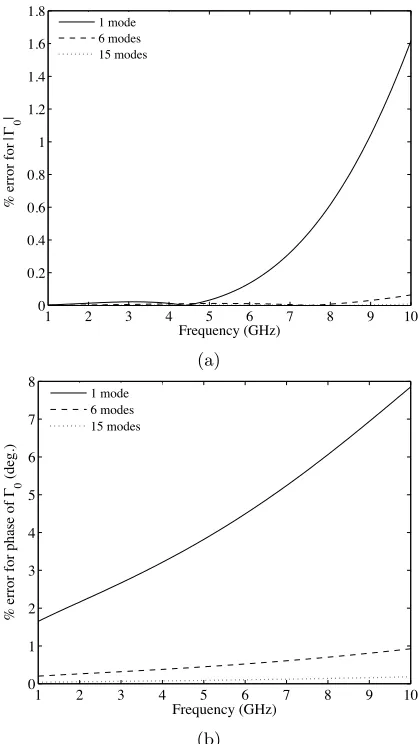
As the solution of the reflection coefficient Γn of the TEM and TM0nis dependent on the number of modes considered, the measurable reflection coefficient Γ0is computed for by considering different number of modes. It is assumed that the final convergence of the solution of Γ0 is obtained by considering twenty modes. Figs. 2(a) and (b) show the plots of the percentage error of the magnitude and phase of Γ0 for the parallel-plate waveguide radiating into an infinite free space for the case of considering one, six, and fifteen modes, with reference to that of twenty modes respectively. As observed in Figs. 2(a) and (b), to achieve a percentage error of less than 1% for both the magnitude and phase of Γ0 it required to consider six modes or more. Hence due to practicality and ease of computations, henceforth for the computations of Γ0, only six modes will be considered. It is noted that in the analyses of the reflection properties of the OEC [23] and open-ended rectangular waveguide [25], the number of modes considered sufficient for computations corresponds to six modes.
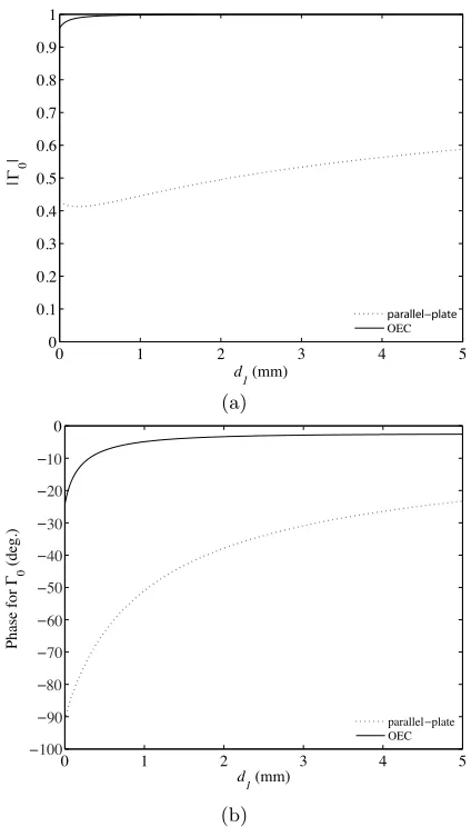
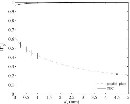
The effect of air gap on the reflection coefficient is of interest in many applications, especially in the measurement of dielectric properties of solids. In the case of the OEC, as the air gap presents a discontinuity between the MUT and the coaxial probe, there may exists a large error in the predicted complex permittivity. This accounts for the reason the probe is recommended for liquid and semi-solid measurements as good contact can be achieved. Therefore using air gap variation between the aperture and the MUT has been proposed as a means of calibration [22, 24]. In this paper, we simulated the dominant mode reflection coefficient Γ0as a function of air gap spacing
d1 between the measuring device and a lossy dielectric of infinite thickness, i.e., N = 2, εr1 = 1, with εr2 arbitrarily selected to be 10−j1; for the case of using the OEC and parallel-plate waveguide probe for measurements. The OEC of inner radiusraand outer radius
1 2 3 4 5 6 7 8 9 10 0
0.2 0.4 0.6 0.8 1 1.2 1.4 1.6 1.8
Frequency (GHz)
% error for
0
1 mode 6 modes 15 modes
|
|
(a)
1 2 3 4 5 6 7 8 9 10
0 1 2 3 4 5 6 7 8
Frequency (GHz)
% error for phase of
0
(deg.)
1 mode 6 modes 15 modes
(b)
Figure 2. Percentage error in the reflection coefficient Γ0, considering different number of modes. (a) Magnitude. (b) Phase.
0 1 2 3 4 5 0
0.1 0.2 0.3 0.4 0.5 0.6 0.7 0.8 0.9 1
d
1 (mm)
OEC
0
|
|
(a)
0 1 2 3 4 5
0
d1 (mm)
Phase for
0
(deg.)
parallel plate OEC 10
20
30
40
50
60
70
80
90
100
(b)
Figure 3. Reflection coefficient Γ0 for dielectric of infinite thickness with varying air gap spacing d1 between the measuring probe and the dielectric at 1 GHz. (a) Magnitude. (b) Phase.
calibration points (different air gaps in the calibration technique) can be used to render more accurate readings for solid measurements using the parallel-plate waveguide probe by taking into consideration d1 in the solution of Γ0.
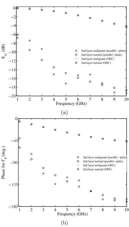
example, in determining malignant growth embedded in benign tissue. In the following, we present a comparative study of the efficiency in identifying a layer of malignant tissue beneath the benign tissue using the different probes. Assuming a 2-layer dielectric media, numerical calculations are done for two cases. Firstly consider the first layer of thickness d1 = 2 cm represents normal breast tissue with the second layer infinite in extent represents abnormal growth. The dielectric properties for the different tissues are as reported in [33]. Subsequently, it is simulated the second layer is having sameεras the first layer, i.e., the dielectric is a homogeneous normal breast tissue.
1 2 3 4 5 6 7 8 9 10 0
Frequency (GHz) S 11
(dB) 2nd layer malignant (parallel plate)
2nd layer normal (parallel plate) 2nd layer malignant (OEC) 2nd layer normal (OEC)
2
4
6
8
10
12
14
16
18
20
(a)
1 2 3 4 5 6 7 8 9 10
0
Frequency (GHz)
Phase for
0
(deg.) 2nd layer malignant (parallel plate) 2nd layer normal (parallel plate) 2nd layer malignant (OEC) 2nd layer normal (OEC)
45
90
135
180
(b)
Figure 4. Reflection coefficient Γ0for 2-layer dielectric withεr2having varying values. (a) Magnitude. (b) Phase.
0 1 2 3 4 5 6 7 8 0
d
1 (mm)
Phase for
0
(deg.)
parallel plate OEC
20
40
60
80
100
120
140
160
180
Figure 5. Phase of reflection coefficient Γ0 for varyingd1 for the two different probes at 1 GHz.
0 0.5 1 1.5 2 2.5 3 3.5 4 4.5 5 0
0.1 0.2 0.3 0.4 0.5 0.6 0.7 0.8 0.9 1
d
1 (mm)
OEC
0
|
|
Figure 6. Magnitude of reflection coefficient Γ0 for varyingd1 for the parallel-plate probe at 1 GHz.
4. CONCLUSIONS AND FUTURE WORK
An improved method using a parallel-plate waveguide probe is proposed for nondestructive dielectric measurements. In the paper, we developed a simple solution for the aperture admittance of the parallel-plate probe radiating into a layered dielectric backed and unbacked by a PEC, derived from the reflection coefficient. Additionally, we have shown that only six modes are necessary to obtain the solution for the reflection coefficient for good accuracy. This is significant in the practical implementation of this technique when solving the inverse problem of extracting the complex permittivity of the material under test as computations will be easily facilitated. Numerical results have also shown that by using a calibration technique taking into consideration air gap variation, the parallel-plate probe may be effective in measuring the dielectric properties of solids. Furthermore, on the assumption that the dielectric properties of the layered media are known, the probe may be used for evaluation of the thickness of layers. Solving the inverse problem [35] will be addressed in the future work.
ACKNOWLEDGMENT
Author Zhang Huiyu thankfully acknowledge the Agency for Science, Technology and Research (A*STAR) of Singapore for providing A*STAR Graduate Scholarship.
REFERENCES
1. He, X., Z. X. Tang, B. Zhang, and Y. Q. Wu, “A newdeembedding method in permittivity measurement of ferroelectric thin film material,” Progress In Electromagnetics Research Letters, Vol. 3, 1–8, 2008.
2. Wu, Y. Q., Z. X. Tang, Y. H. Xu, X. He, and B. Zhang, “Permittivity measurement of ferroelectric thin film based on CPW transmission line,” Journal of Electromagnetic Waves and Applications, Vol. 22, No. 4, 555–562, 2008.
3. Wu, Y. Q., Z. X. Tang, Y. H. Xu, X. He, and B. Zhang, “Effect of high-Q Ba4Ti13O30 materials on the dielectric properties of (Bax,Sr1-x) TiO3 films for microwave communication,”Journal of Electromagnetic Waves and Applications, Vol. 21, No. 11, 1445– 1451, 2007.
loss prediction in urban street grid microcellular environments,” IEEE Trans. Veh. Tech., Vol. 54, No. 4, 1251–1258, July 2005. 5. Zhang, J. T., M. Nakhash, and Y. Huang, “Electromagnetic
imaging of layered building materials,”Measurement Science and Technology, Vol. 12, 1147–1152, May 2001.
6. Bassey, C. E. and G. R. Simpson, “Aircraft ice detection using time domain reflectometry with coplanar sensors,” IEEE Aerospace Conference 2007, 1–6, March 3–10, 2007.
7. Zainud-Deen, S. H., M. E. S. Badr, E. El-Deen, K. H. Awadalla, and H. A. Sharshar, “Microstrip antenna with defected ground plane structure as a sensor for landmines detection,”Progress In Electromagnetics Research B, Vol. 4, 27–39, 2008.
8. Capineri, L., D. Daniels, P. Falorni, O. Lopera, and C. Windsor, “Estimation of relative permittivity of shallowsoils by using the ground penetrating radar response from different buried targets,” Progress In Electromagnetics Research Letters, Vol. 2, 63–71, 2008. 9. Zainud-Deen, S. H., M. E. S. Badr, E. El-Deen, and K. H. Awadalla, “Microstrip antenna with corrugated ground plane structure as a sensor for landmines detection,”Progress In Electromagnetics Research B, Vol. 2, 259–278, 2008.
10. Chen, X., D. Liang, and K. Huang, “Microwave imaging 3-D buried objects using parallel genetic algorithm combined with FDTD technique,” Journal of Electromagnetic Waves and Applications, Vol. 20, No. 13, 1761–1774, 2006.
11. Zainud-Deen, S. H., W. M. Hassen, E. M. Ali, and K. H. Awadalla, “Breast cancer detection using a hybrid finite difference frequency domain and particle swarm optimization techniques,”Progress In Electromagnetics Research B, Vol. 3, 35–46, 2008.
12. Yan, L. P., K. M. Huang, and C. J. Liu, “A noninvasive method for determining dielectric properties of layered tissues on human back,” Journal of Electromagnetic Waves and Applications, Vol. 21, No. 13, 1829–1843, 2007.
13. Lonappan, A., V. Thomas, and G. Bindu, “Nondestructive measurement of human blood at microwave frequencies,”Journal of Electromagnetic Waves and Applications, Vol. 21, No. 8, 1131– 1139, 2007.
14. Bindu, G., A. Lonappan, V. Thomas, C. K. Aanandan, and K. T. Mathew, “Dielectric studies of corn syrup for applications in microwave breast imaging,” Progress In Electromagnetics Research, PIER 59, 175–186, 2006.
C. K. Aanandan, and K. T. Mathew, “Active microwave imaging for breast cancer detection,”Progress In Electromagnetics Research, PIER 58, 149–169, 2006.
16. Mehta, P., K. Chand, D. Narayanswamy, D. G. Beetner, R. Zoughi, and W. V. Stoecker, “Microwave reflectometry as a novel diagnostic tool for detection of skin cancers,” IEEE Trans. Instrum. Meas., Vol. 55, No. 4, 1309–1316, August 2006.
17. Lonappan, A., G. Bindu, V. Thomas, J. Jacob, C. Rajasekaran, and K. T. Mathew, “Diagnosis of diabetes mellitus using microwaves,”Journal of Electromagnetic Waves and Applications, Vol. 21, No. 10, 1393–1401, 2007.
18. Semenov, S. Y., V. G. Posukh, Y. E. Sizov, A. E. Bulyshev, A. Souvorov, A. Nazarov, T. C. Williams, and P. N. Repin, “Microwave tomographic imaging of the heart in intact swine,” Journal of Electromagnetic Waves and Applications, Vol. 20, No. 7, 873–890, 2006.
19. Challa, R. K., D. Kajfez, V. Demir, J. R. Gladden, and A. Z. Elsherbeni, “Permittivity measurement with a non-standard waveguide by using TRL calibration and fractional linear data,” Progress In Electromagnetics Research B, Vol. 2, 1–13, 2008. 20. Dankov, P. I., “Two-resonator method for measurement of
dielectric anisotropy in multilayer samples,”IEEE Trans. Microw. Theory Tech., Vol. 54, No. 4, Part 1, 1534–1544, June 2006. 21. Stuchly, S. S. and M. A. Stuchly, “Coaxial line reflection
method for measuring dielectric properties at radio and microwave frequencies, a review,” IEEE Trans. Instrum. Meas., Vol. 29, No. 3, 1640–1648, 1999.
22. Ganchev, I. S., N. Qaggoumi, S. Bakhtiari, and R. Zoughi, “Calibration and measurement of dielectric properties of finite thickness composite sheets with open-ended coaxial sensors,” IEEE Trans. Instrum. Meas., Vol. 44, No. 6, 1023–1029, December 1995.
23. Baker-Jarvis, J., M. D. Janezic, P. D. Domich, and R. G. Geyer, “Analysis of an open-ended coaxial probe with lift-off for nondestructive testing,” IEEE Trans. Microw. Theory Tech., Vol. 43, No. 5, 711–718, October 1994.
24. Bakhtiari, S., S. I. Ganchev, and R. Zoughi, “Analysis of radiation from an open-ended coaxial line into stratified dielectrics,” IEEE Trans. Microw. Theory Tech., Vol. 42, No. 7, Part 1–2, 1261–1267, July 1994.
radiating into a dielectric half-space: The forward and inverse
problems,” IEEE Trans. Instrum. Meas., Vol. 48, No. 6, 1131–
1140, December 1999.
26. Qaddoumi, N., R. Zoughi, and G. W. Carriveau, “Microwave
detection and depth determination of disbounds in
low-permittivity and low-loss thick sandwich composites,” Res.
Nondestruct. Eval., Vol. 8, No. 1, 51–63, 1996.
27. Bakhtiari, S., N. Qaggoumi, I. S. Ganchev, and R. Zoughi, “Microwave noncontact examination of disband and thickness
variation in stratified composite media,” IEEE Trans. Microw.
Theory Tech., Vol. 42, No. 3, 389–395, March 1994.
28. Hyde IV, M. W., and M. J. Havrilla, “A nondestructive technique for determining complex permittivity and permeability of magnetic sheet materials using two flanged rectangular
waveguides,” Progress In Electromagnetics Research, PIER 79,
367–386, 2008.
29. Trabelsi, S. and S. O. Nelson, “Nondestructive sensing of physical properties of granular materials by microwave permittivity
measurement,”IEEE Trans. Instrum. Meas., Vol. 55, No. 3, 953–
963, June 2006.
30. Wu, W. and C. E. Smith, “Dielectric measurements using the
HP 85070A probe,” Proc. 1992 IEEE Proceedings Southeastcon,
Vol. 1, 83–86, 1992.
31. Hewlett Packard User’s Manual, HP 85070B Dielectric Probe Kit. 32. Nelson, S. O. and P. G. Bartley, Jr., “Open-ended coaxial-line
permittivity measurements on pulverized materials,”IEEE Trans.
Instrum. Meas., Vol. 47, No. 1, 133–137, February 1998.
33. Zhang, H., S. Y. Tan, and H. S. Tan, “A novel method for
microwave breast cancer detection,”Progress In Electromagnetics
Research, PIER 83, 413–434, 2008.
34. Lee, J. W., H. J. Eom, and J. H. Lee, “TM-wave radiation
from flanged parallel-plate into dielectric slab,”IEE Proc. Microw.
Antennas Propag., Vol. 143, No. 3, June 1996.
35. Huang, C.-H., Y.-F. Chen, and C.-C. Chiu, “Permittivity distribution reconstruction of dielectric objects by a cascaded
method,” Journal of Electromagnetic Waves and Applications,