Design And Simulation Of Retrofitting Vehicles With Solar Powered
System
R VENKATESH and Dr. M. Manzoor Hussain
M.Tech in Mechatronics, JNTUHCEH Hyderabad
Email: [email protected]
Email: [email protected]
Professor in Mechanical Engineering & Director of Admissions Mechanical Engineering
JNTUH College of Engineering Hyderabad
ABSTRACT
According to the current
environmental conditions, the pollution percentage of pollutants exerted by the existing conventional vehicle is much higher than the estimated results. This paper presents a conceptual design of converting a conventional vehicle into a plug-in hybrid electric vehicle (PHEV) to reduce the pollution percentage in the
conventional vehicle. The proposed
propulsion system is configured as a parallel-hybrid concept. The vehicle will undergo with minimal changes. A model of variable drive systems provide a higher efficient drive axles in both front and rear wheels with respect to the source of energy used is defined. The front wheel could run with the IC combustion engine and the rear wheel with the in-wheel motor-hub, then providing the external control to the motor so that the speed of the motor can be controlled. A dual selection is provided at the choice of the user, to match their style of drive either in normal or electric drive modes. The model is built in the MATLAB /SIMULINK tool and its
Performance analysis is done with the results obtained.
Index terms:
1. INTRODUCTION
In present, the situation of using up
the world reserve of fossil fuel as well as
the concern on environment is forcing the
Automobile manufacturers to seek for
alternative propulsion concepts to operate
by other energy sources. As a result, the
electric propulsion concept has come into
interest. In electric vehicles, the consumed
energy may come from different origins
e.g. hydrogen(fuel cell), renewable energy
(from grid) or even fossil fuel (generator
driven by combustion engine). This
reduces the consumption of fossil fuel. The
high efficiency in energy conversion, the
possibility of regenerative braking, low
emission, low acoustic noise, control
flexibility and renewable energy source.
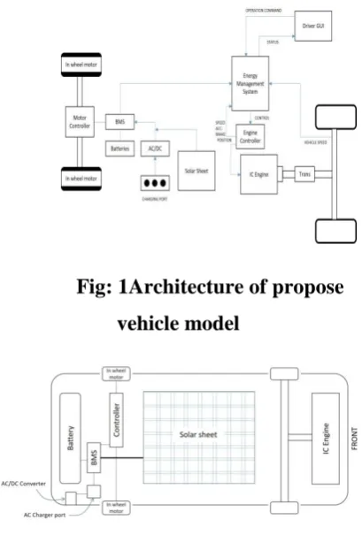
Fig: 1Architecture of propose
vehicle model
Figure : Architecture of proposed vehicle.
However, the implementation of
electric vehicles still has many technical
challenges to be solved. For example, the
energy density of the energy storage, e.g.
batteries, is not sufficient to run the vehicle
with the comparable driving range in
comparison to conventional vehicles. In
order to overcome the limitation by the
battery, the hybrid solution is proposed to
combine the electric propulsion system
with an additional on-board power supply
for recharging the batteries. This power
supply can be a fuel cell or a generator
driven by a internal combustion engine.
This vehicle type is called hybrid electric
vehicle (HEV).
The reduction of gasoline
consumption as well as the CO2 emission
by using HEV has been reported.
Moreover, the commercial success of the
Prius HEV by Toyota has confirmed the
claimed advantages. Due to the success of
Toyota, other manufacturers have begun to
develop their own HEV technology.
However, the market of HEV technology
is not limited only to the market of new
cars. Converting conventional vehicle to
HEVs is a high potential market.
Retrofitting a used car will be also an
interesting choice for people who wish to
use the HEV technology in a low price.
Electric vehicle is an automobile
propelled by one or more electric motors,
drawing power from an onboard source of
electricity. Electric cars are mechanically
simpler and more durable than
gasoline-powered cars. They produce less pollution
than do gasoline-powered cars. An electric
car stores its energy on board-typically in
batteries, but alternatively with capacitors
The aim of this work is to develop
and prove the retrofitting concept to
transform conventional vehicle to HEVs.
This paper presents the design concept, the
methods of dimensioning components
including the hardware layout and
simulation results were placed in the
documentation.
2. LITERATURE REVIEW
2.1 MODELING AND SIMULATION
Karen et al (1999) presented a
simulation and modelling package
developed at Texas A&M University,
V-Elph 2.01. V-V-Elph was written in
theMatlab/Simulink graphical simulation
language and is portable to most computer
platforms. They also discussed the
methodology for designing vehicle drive
trains using the V-Elph package. An EV, a
series HEV, a parallelHEV and a
conventional internal combustion engine
driven drive train have been designed
using the simulation package. Simulation
results such as fuel consumption, vehicle
emissions, and complexity are compared
and discussed for each vehicle. a Xianmin
(2002) developed a novel propulsion
system design scheme for EVs requiring
high power density. The theory analysis
Brian (2007) created a model in
MATLAB and ADAMS to demonstrate its
fuel economy over the conventional
vehicle. He used the Honda IMA
(Integrated Motor Assistant) architecture,
where the electric motor acts as a
supplement to the engine torque. He
showed that the motor unit acts as
generator during the regenerative braking.
He used a simple power management
algorithm in the power management
controller he designed for the vehicle.
Cuddy and Keith (2007) performed a
parallel and series configured hybrid
vehicles likely feasible in next decade are
defined and evaluated using flexible
Advanced Vehicle Simulator (ADVISOR).
Fuel economies of two diesel powered
hybrid vehicles are compared to a
comparable technology diesel powered
internal combustion engine vehicle. The
fuel economy of the parallel hybrid
defined is 24% better than the internal
combustion engine Vehicle and 4% better
than the series hybrid
2.2 CONTROL SYSTEM
The effectiveness of fuel
consumption depends not only on vehicle
design but also on the control strategy
used. The control strategy provides a
dynamic control of the vehicle to ensure
the best utilization of the onboard energy
conditions. So, the energy management
strategy is extremely important to decide
how and when energy will be provided by
various sources of PHEV. In 1999, AVL
Company proposed a hybrid system that
used a 50 cccarburetted lean-burn
two-stroke engine with a 0.75 kW electric
motor mounted on the engine crankshaft
mainly to provide increased torque during
acceleration.
Yimin and Mehrdad (2006)
introduced a speed and torque coupling
hybrid drive train. In this drive train, a
planetary gear unit and a generator/motor
decouple the engine speed from the vehicle
wheel speed. Also, another shaft-fixed
gear unit and traction motor decouple the
engine torque from the vehicle wheel
torque. Thus, the engine can operate within
its optimal speed and torque region, and at
the same time, can directly deliver its
torque to the driven wheels. They also
discussed the fundamentals architecture,
design, control, and simulation of the drive
train. Simulations show that the fuel
economy in urban and highway driving
cycles can be greatly improved. Kuen-Bao
and Tsung-Hua (2006) incorporated a
mechanical type rubber V-belt,
continuously-variable transmission (CVT)
and chain drives to combine power of the
two power sources, a gasoline engine and
an electric motor in hybrid power system.
The system uses four different modes in
order to maximize the performance and
reduce emissions: electric-motor mode;
engine mode; engine/charging mode; and
power mode. The main advantages of this
new transmission include the use of only
one electric motor/generator and the shift
of the operating mode accomplished by the
mechanical-type clutches for easy control
and low cost. Kinematic analyses and
design are achieved to obtain the size of
each component of this system. A design
example is fabricated and tested.
2.3 ELECTRIC PROPULSION AND
ENERGY STORAGEDEVICE
In the area of propulsion motor and
other motor control technologies, methods
to eliminate speed/position sensors,
inverter current sensors, etc., have been
under investigation for several years. The
technological challenges for the electric
motors will be light weight, wide speed
range, high efficiency, maximum torque
and long life. Most hybrid hardware
subsystems and components with
exception of energy storage devices have
been matured to an acceptable level
efficiency performance and reliability. As
per the studies, the energy stored in the
in the EV unit. It is also clear that the
power capability of the batteries designed
for HEVs is much higher than those
designed for EVs. However, batteries for
plug-in hybrid electric vehicles require
both high energy density and high-power
capability based on the driving
requirements. The other significant
technical challenges include higher initial
cost, cost of battery replacement, added
weight and volume, performance and
durability.
2.4INFLUENCE OF DRIVING CYCLE
Sukanya et al (2006) proposed a method to develop a driving cycle representing the Bangkok traffic. A method for selecting the representative road routes in Bangkok was firstly proposed. A gasoline passenger car equipped with a real time data logger was then used to collect speed-time data under actual traffic along the selected road routes in Bangkok urban area for two months. The driving characteristics were analyzed from the speed-time data and its target driving parameters were defined and evaluated. The method for generating the driving cycle was then proposed and described. After achieving a driving cycle, exhaust emissions and fuel consumption of a vehicle were measured by driving a car on a standard chassis dynamometer according to the obtained Bangkok driving cycle. Comparison of the exhaust emission test and fuel consumption test results obtained from the constructed driving cycle with those obtained from the
presently-adopted European standard cycle had been made.
3. METHODOLOGIES
OBJECTIVES AND METHODOLOGY
3.1 OBJECTIVES
The objectives of the research work are stated as follows.
i) To develop a simple vehicle model and simulation for sizing of power train components followed by selection of power train components.
ii) To propose and develop a simple control strategy for the plug-in hybrid electric four-wheeler suitable for city driving conditions.
iii) To develop a plug-in hybrid
electric four-wheeler by converting
available conventional four-wheeler with a suitable motor and battery.
3.2 METHODOLOGY
To achieve the above stated objectives, the following methodologies are to be used.
i) A Simulink simscape vehicle model will be developed and MATLAB simulation will be carried out for evaluation of power and energy requirements for a plug-in hybrid electric four-wheeler for different driving cycles.
ii) A simple control strategy has to be
developed for Indian city driving
conditions with less fuel consumption for reducing emissions.
iii) A conventional four-wheeler will be converted into a plug-in hybrid electric four-wheeler by retrofitting a hub motor in the rare wheel.
4. ELECTRIC VEHICLE
A more recent development is the
hybrid electric vehicle (HEV), which uses
both an electric motor or motors and a
gasoline or diesel engine, which charges
the batteries in order to extend the car's
range and often to provide additional
power. Regardless of the energy source, an
electric car needs a controller, which is
connected to the accelerator pedal, for
directing the flow of electricity from the
energy source to the motor. Most electric
cars use lead-acid batteries, but new types
of batteries, including zinc-chlorine, nickel
metal hydride and sodium-sulphur, are
becoming more common. The motor of an
electric car harnesses the battery's
electrical energy by converting it to kinetic
energy. The driver simply switches on the
power. selects "Forward" or "Reverse"
with another switch and steps on the
accelerator pedal While the
internal-combustion engine of a conventional car
has many moving parts and must convert
the linear motion of pistons and rods into
140 rotary motion at the wheels, an electric
motor has only a single rotating element.
Like a gasoline-powered car, an electric
car has a system (called a power train) of
gears, shafts. and joints that transmit
motion from the motor to the car wheels.
Most electric cars do not have clutches or
multi speed transmissions. In order to go
backward, the flow of electricity through
the motor is reversed, changing the
rotation of the motor and causing the
power train to make the wheels rotate in
the other direction.
4.2.1 Battery Electric Vehicles (BEV)
Battery Electric Vehicles, also
called BEVs, and more frequently called
EVs, are fully-electric vehicles with
rechargeable batteries and no gasoline
engine. Battery electric vehicles store
electricity onboard with high-capacity
battery packs. Their battery power is used
to run the electric motor and all onboard
electronics. BEVs do not emit any harmful
emissions and hazards caused by
traditional gasoline-powered vehicles.
BEVs are charged by electricity from an
external source. Electric Vehicle (EV)
chargers are classified according to the
speed with which they recharge an EVs
battery. The classifications are Level 1,
Level 2, and Level 3 or DC fast charging.
Level 1 EV charging uses a standard
household (120v) outlet to plug into the
electric vehicle and takes over 8 hours to
charge an EV for approximately 75-80
miles. Level one charging is typically done
at home or at your workplace. Level 1
chargers have the capability to charge most
requires a specialized station which
provides power at 240v. Level 2 chargers
are typically found at workplaces and
public charging stations and will take
about 4 hours to charge a battery to 75-80
miles of range. Level 3 charging, DC fast
charging, or simply fast charging is
currently the fastest charging solution in
the EV market. DC fast chargers are found
at dedicated EV charging stations and
charge a battery up to 90 miles range in
approximately 30 minutes.
4.2.2 Plug-in Hybrid Electric Vehicle (PHEV)
Plug-in Hybrid Electric Vehicles or PHEVs can recharge the battery through both regenerative braking and “plugging in” to an external source of electrical power. While “standard” hybrids can (at low speed) go about 1-2 miles before the gasoline engine turns on, PHEV models can go anywhere from 10-40 miles before their gas engines provide assistance.
4.2.3 BACKGROUND HEV
Is defined as the technology in which there are more than one energy source used in which at least one source will be electricity. There are three main types of HEVs. All HEV systems are equipped with an electric motor, an ICE and a generator. They may be considered either series, parallel, or series-parallel
depending on how the system is
configured. Series hybrid is very similar to an EV, in that the electric motor moves the vehicle. The gasoline engine is there only
to provide added power to the motor via the inverter, and acts as a range extender. A parallel hybrid is where the power to the drive train is shared by ICE and the motor
Figure: 4.1 Series-Parallel HEV
Drive Block Diagram
HEV’s series-parallel combination
of electric drive is powered by a battery
and a mechanical drive using the legacy
ICE engine powered by fuel. The wheels
can be driven by ICE engine and electric
traction motor. Both systems are connected
to the drive shaft of the vehicle.
Figure: 4.2 Series-Parallel Hybrid Drive
System
The required power produced by
the ICE is through the combustion of fuel
as the source of power. For the traction
motor, the source of power is the battery.
The main idea here is to use electrical
drive as long as possible, before the ICE
must be used for longer journey, as
required, to minimize use of fuel as much
as possible. This concept requires the
vehicle to use as big a battery as possible.
limitations, battery is limited in the amount
of energy that it can store in the space
provided. In order to keep the currents low
to minimize I2R losses in wires, battery is
typically designed to be high voltage in the
range of 200V to 500V
4.2.4 VEHICLE LOAD MODEL
Vehicle load can be a function of
multiple variables, including
aerodynamics. Here, we take into account
the parameters that provide the largest
effects on the vehicle in terms of load.
Vehicle load model equations are below.
Accelerating mass of vehicle will be the
force on the wheels. Wheel force is then
calculated as
MTis the total mass calculated as
MT=Mveh+ MtireThe torque on wheels can
be determined as
5. CHAPTER
MATLAB/Simulink Modelling
5.1 System Modelling
A system based model was developed by using SIMULINK library
tool .The five main parts to the overall model are motor model, vehicle model, gear box model, control block model, and power balance and energy calculations. Complete high-level model of the system is shown below in Figure 13. Four main blocks that were developed as parts of the overall model are control, motor model, gear box and vehicle load model. Details of these blocks are discussed in the subsequent sections. Power energy block is simply used to calculate and store the input and output power and energy values during the drive cycle
5.2 Motor Modelling
A PMSM motor model was
developed based on the state equations in
d-q reference frame. This allows for easier
control of the currents. The model uses the
Park’s transformed variables in d-q
reference frame. Motor model is shown
below in. Model developed here in
Simulink is based on the state. These
blocks such as integrator, summing
junction, multipliers, and dividers, to
represent the full state equation. As an
example, idsis the state output, Ld, Lq, and
Rs are motor parameters which are
constants, and vds andiqs are inputs.
5.3 Control Modelling
Proportional integral differentiator
(PID) type controllers are quite common in
the industry. This model uses a simple PI
based control loop for vehicle speed
control. Also, the q-axis current can be
controlled in the same loop. The d-axis
current is controlled to zero “0”amps,
since only the q axis current produces
torque. The gains, Kp and Ki, were chosen
to provide a critically damped response to
a step input, as well as a reasonable steady
state error of less than 2%. This model
consists of amplifiers, inverters and all
other important functions which are used
in the control systems to check the stability
and characteristic of the model.
Figure: 5.3Simulink model of control system
6. CONCLUSION
In this research work, a conceptual
model for retro-fitting a conventional
vehicle into a plug-in hybrid vehicle is
studied. Various power sources were
studied and implemented based on the
conceptual requirement in the module.
Various simulations were executed to
analyse the performance of the proposed
implementation in the vehicle in
converting plug-in hybrid vehicle. The
simulations were studied and a successful
concept was proposed in converting a
conventional vehicle into a HEV. The
proposed concept can be implemented in
existing in conventional vehicle system to
upgrade BS4 configurations into
successful BS6 configurations to meet
pollution standards and other standards can
be met. To increase the engine efficiency
and vehicle’s overall efficiency based on
futuristic applications; effective battery
management (than the proposed battery
system), Electrical Brake control, and
security system can be studied and
implemented for plug-in Hybrid vehicle.
REFFERENCES
1) D. Doerffel and S. A. Sharkh, "System
Modelling and Simulation as a Tool for
Electric Vehicle Drive train
Configurations," in IEEE Vehicle Power
and Propulsion Conference, pp. 1 - 6,
September 2006.
2) M. Olszewski, "Evaluation of the 2010
Toyota Prius Hybrid Synergy Drive
System," U.S. Department of Energy,
Washington, D.C., 2011.
3) P. Mishra, S. Saha and H. Ikkurti,
"Selection of Propulsion Motor and
Suitable Gear Ratio for Driving Electric
Vehicle on Indian City Roads,"
International Conference on Energy
Efficient Technologies for Sustainability,
pp. 692-698, April 2013.
4) M. Bertoluzzo, P. Bolognesi and G.
Buja, "Role and Technology of the Power
Split Apparatus in Hybrid Electric
Vehicles," in The 33rd Annual Conference
of the IEEE Industrial Electronics Society,
Taipei, pp. 256 - 261, November 2007.
5)A. E. Bayrak, Y. Ren and P. Y.
Papalambros, "Design of Hybrid-Electric
Vehicle Architectures using
Auto-Generation of Feasible Driving Modes,"
ASME 2013 International Design
Engineering Technical Conferences and
Computers and Information in Engineering
Conference, Portland, pp. 1 - 9, August