Compact Multi-Band Filter Based on Multi-Ring Complementary
Split Ring Resonators
Imene Sassi1, *, Larbi Talbi1, and Khelifa Hettak2
Abstract—A novel multi-band band-reject filter based on multi-ring complementary split-ring resonators (multi-ring CSRRs) is presented. The proposed filter is realized by etching the multi-ring CSRRs in the ground plane beneath a microstrip line. The multi-ring CSRR offers the possibility of designing multi-band filters with a small size and simple structure. To validate the proposed prototype of the multi-band filter, a dual-band and tri-band filters were fabricated and tested. The proposed filters show a good multi-band property to satisfy the requirement of WLAN in the 2.4/5.8 GHz bands and WiMAX in the 2.5/3.4 GHz bands. A good agreement between experimental and simulated results is obtained.
1. INTRODUCTION
Metamaterials are artificially synthesized materials which produce attractive physical properties unavailable in the conventional material [1]. It can exhibit exotic negative refractive index, inverse Snell’s law and reversed Doppler effects. The dimensions of metamaterial inclusions are small compared to the wavelength at the resonance. Split ring resonator was the first particle proposed for the implementation of metamaterial [2]. In fact, to achieve a negative effective permeability in a certain frequency range, the metamaterial can be designed based on split ring resonators (SRRs) or similar geometries [3, 4]. These structures have been widely described as basic resonators to construct miniaturized microwave circuits. Using SRRs, the miniaturization can be realized by taking advantage of the well-known sub-wavelength effect of these structures [5]. In particular, split-ring resonator (SRR) can be used as a basic particle for the design of stopband negative permeability structure [6]. The possibility of designing bandpass and band-reject filters using split ring resonator has been demonstrated in various studies [7–9]. In 2004, a stopband microstrip line based on complementary split ring resonators (CSRRs) was fabricated by Falcone et al. [10]. Moreover, it was demonstrated that the split ring resonator SRR has a very narrow band response compared to the complementary split ring resonator [11]. Recently, complementary split ring resonator is more frequently used for the design of filters with wide and deep stopbands [12–15]. Band-reject filters were as well designed based on the defected ground structure (DGS) technology [16– 19]. This technology plays an important role in the improvement of the performance of bandstop filters. To suppress the spurious signals, it is necessary to use a band-reject filter. By cascading U-shaped DGS, Xiao et al created dual and tri-band bandstop filters [20]. It has been demonstrated that U-shaped defected ground structure has a better stopband performance compared with conventional dumbbell ones. Not only has the U-shaped DGS provided a very narrow band rejection but it has also offered more miniaturization. The designed multi-band filters based on U-shaped DGS were the only bandstop filters reported in the literature, that only use a simple DGS pattern. Inspired by the same methodology and in order to design a multi-band band-reject filter, a multi-ring CSRR will be introduced. In [21], Turkmen et al. proposed a newN-ring SRR unit cell for multi-band metamaterials.
Received 19 April 2015, Accepted 18 May 2015, Scheduled 22 May 2015
* Corresponding author: Imene Sassi ([email protected]).
The multi-band resonator is composed of a number N of different concentric split rings. The N-ring generates N different resonance frequencies and engenders a magnetic resonance for each frequency. In fact, the value of each resonance response can be adjusted by varying the geometrical parameters of each ring resonator and also by changing the design parameters. In this paper, a compact multi-band band-reject filter using multi-ring complementary split ring resonators (multi-ring CSRRs) is proposed. As a proof of concept, two filters are designed and simulated for two different cases (for N = 2 and 3). The center frequencies of the filters are 2.4 GHz, 3.4 GHz and 5.8 GHz. Compared to the dual and tri-band filters presented in [20], the designed filters offer a wider bandwidth for the different reject-bands. The prototype of the filter provides the possibility of generating more operation bands as the number of the stopbands is tuned by the numberN of the CSRR rings. The filters are fabricated and experimentally tested. The experiment and simulation results demonstrate a good agreement.
2. DESIGN APPROACH
2.1. Multi-Ring Complementary Split-Ring Resonator
Multi-ring CSRR can be derived from a simple structure of the multi-ring SRR using the concepts of duality. As reported by the Babinet principle, to obtain the complementary of any structure, the planar metallic traces of the original multi-ring SRR are replaced with apertures and the apertures are replaced with metal plates. The multi ring complementary split ring resonator is the dual of the original one (multi-ring SRR). Furthermore, the negative permeability is transformed to a negative permittivity in the case of the multi-ring CSRR. For the multi-ring CSRR, the number of the resonances can be determined by the CSRR rings placed in the unit cell. This means that if a designed multi-ring CSRR has N-rings it will generate N resonances. The distinct resonances are mainly due to self and mutual couplings of each CSRR ring. The multi-ring CSRR are etched in a dielectric substrate with a thickness of 1.27 mm and a relative dielectric constant (r = 10.2). The commercial software Ansoft HFSS is used to perform the analysis of the S-parameter of the different multi-ring CSRR unit cells. Figure 2 illustrates the simulated transmission coefficients of three different unit cells. The first unit cell is a simple CSRR ring, the second and third unit cells are formed by two and three CSRR rings respectively (prototypes are shown in Figure 1). The optimized geometrical parameters of the three unit cells are recapitulated in Table 1. As shown in Figure 2, the second and the third stopbands have the same performance in term of bandwidth. It has been demonstrated in [20] that the U-shaped DGS generates
(a) (b)
(c)
Figure 1. (a) One-ring CSRR. (b) Two-ring CSRR. (c) Three-ring CSRR.
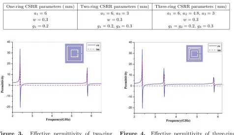
Table 1. Geometrical parameters of multi-ring CSRR.
One-ring CSRR parameters ( mm) Two-ring CSRR parameters ( mm) Three-ring CSRR parameters ( mm)
a1= 6 a1= 6,a3= 3 a1= 6,a2= 4.8,a3= 3
w= 0.3 w= 0.3 w= 0.3
g1= 0.2 g1= 0.2,g3= 0.3 g1=g2= 0.2,g3= 0.3
Figure 3. Effective permittivity of two-ring CSRR.
Figure 4. Effective permittivity of three-ring CSRR.
narrower bandwidth for the second and the third bands. In fact, these bands are created by the DGS coupling and not by the intrinsic proprieties of the DGS. In the case of the multi-ring CSRR, the second and the third bands are created by the self and mutual couplings of each CSRR ring. Consequently, it can be deduced that the multi-ring CSRR provides the possibility of creating multi-band band-reject structure combining the intrinsic proprieties of each ring and the coupling between the different rings. The S-parameters of each unit cell and the position of the resulting resonant frequency have been determined using a time varying electromagnetic field. Afterwards, the effective permittivity of the multi-ring CSRR is determined from the physical quantities of the reflection coefficient S11 and the transmission coefficient S21 based on the extraction formula [22, 23]. Figure 3 illustrates the negative permittivity characteristics of the two-ring CSRR. The geometric characteristics of the complementary two-ring cells are illustrated in Figure 1(b) and detailed in Table 1. It can be inferred from Figure 3 that the two-ring CSRR have two resonance frequencies. The first ring CSRR resonates at 2.4 GHz and its relative permittivity is truly negative from 2.39 GHz to 2.53 GHz. The second ring CSRR resonates at 5.8 GHz and its equivalent effective permittivity is negative from 5.81 GHz to 5.94 GHz. The physical dimensions of the three-ring CSRR are shown in Figure 1(c). These dimensions were optimized to obtain three distinct resonances. The optimized dimensions are recapitulated in Table 1. Compared to the two-ring CSRR cell, three-ring CSRR inclusion has three distinct resonance frequencies. As shown in Figure 4, there are three different electric resonances respectively at 2.4 GHz, 3.4 GHz and 5.8 GHz. From Figure 3 and Figure 4, it can be noticed that the desired number of resonance frequencies can be controlled by the number of the rings in one CSRR unit cell. As a result, by choosing the number of the CSRR rings, the corresponding number of electric resonances can be easily realized. The two multi-ring CSRR inclusions already simulated will be applied to create multi-band filters.
2.2. Multi-Band Filters Configuration
(a) (b)
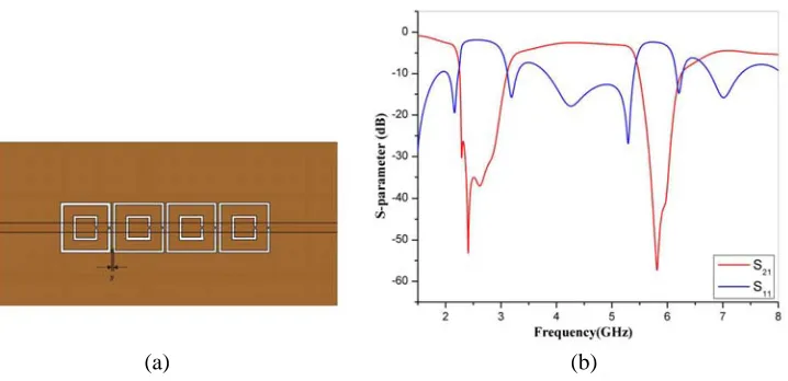
Figure 5. (a) Configuration of dual-band filter with four two-ring CSRRs etched in the ground plane, (b) simulated scattering parameters of dual-band filter.
(a) (b)
Figure 6. (a) Configuration of tri-band filter with four three-ring CSRRs etched in the ground plane, (b) simulated scattering parameters of tri-band filter.
perpendicular to the ground plane. The multi-ring CSRRs will have negative permittivity when an electric field is perpendicular to the plane of these inclusions. Hence, the multi-ring CSRR etched in the ground plane just below the microstrip line create a stopband with strong electric coupling. Based on this theory, two categories of bandstop filters are designed. The first prototype is a dual-band filter based on a two-ring CSRR. The second designed filter is a tri-band filter based on a three-ring CSRR. The Rogers RO3010 substrate used is with a dielectric constant of 10.2 and a thickness of 1.27 mm. To make the line’s characteristics impedance 50 Ω, the width of the microstrip line is set to 1.2 mm. As shown in Figure 5(a), four unit cells of two-ring CSRR are etched in the ground with a distance of s = 0.3 mm between each two unit cells. These four unit cells are introduced to achieve a dual-band response. On the other hand, to achieve a tri-band response, four three-ring CSRRs are loaded in the ground of the tri-band filter (a prototype is shown in Figure 6(a)) with the same distancesof 0.3 mm.
3. RESULTS AND DISCUSSIONS
Figure 7. Effect of varying a3 on the transmission response of the dual-band filter.
Figure 8. Effect of varying a2 on the transmission response of the tri-band filter.
2.4 GHz. The second stopband is detected from 5.5 to 6.23 GHz. For this stopband, the center frequency is 5.8 GHz allowing the FBW of 12.5%.
The simulated reflection coefficient of the tri-band filter is shown in Figure 6(b). The filter generates very high rejection with sharp cutoffs in three different bands. The three stopbands extend from 2.23 to 3.06 GHz, 3.34 to 3.91 GHz and 5.63 to 6.17 GHz. The centre frequency of the first stopband is 2.4 GHz yielding the FBW of 34.5%. From Figure 6(b), it is noticed that the second and the third stopbands of this filter are centered at 3.4 GHz and 5.8 GHz with the fractional bandwidth of 16.7% and 9%, respectively.
In the proposed filters, the resonance frequencies of the multi-ring CSRR cells were adjusted at 2.4 GHz, 3.4 GHz, and 5.8 GHz respectively, which can be designed by tuning the geometrical parameters. In the process of design, the variation of the geometric parameters of the multi-ring CSRR cells can be easily applied to determine the center frequencies of the stopbands and the bandwidth of each stopband. Therefore, the topologies of the designed filters have a great flexibility. In fact, the resonance frequency of the multi-ring CSRR can be tuned by changing the geometric parameters such as the side length of the ring, the distance between two rings, the aperture width. In order to investigate the effect of the multi-ring CSRR geometrical parameters on dual and tri-band response of the designed filters, a parametric study is performed. In the case of the dual-band filter, the side length a3 is varied from 3 mm to 5 mm and the transmission coefficientS21 of the filter is numerically computed. Figure 7 illustrates the transmission coefficient of the dual-band filter when varying the side length a3 of the small ring. While the first center frequency is kept intact, the second center frequency has been shifted down as increasing the side length a3. From Figure 7, it is clearly observed that the second stopband of the filter can be easily displaced from 5.8 GHz to 3.2 GHz. It has been demonstrated in [24] that the CSRR behaves as an LC resonator. The total inductance of this resonator is created by the inductive coupling between the external and internal strips around the slotted rings. Moreover, the resonance frequency of an LC resonator can be expressed as a function of the capacitance and the inductance fr = 1
2π√LC. Hence, when the side length of each CSRR ring increases, the effective inductance of the inclusions increases and gives rise to a lower center frequency. As shown in Figures 7, 8 and 9, each center frequency depends on the side length of the concentric ring CSRR that generates this frequency. Hence, not only each center frequency can be controlled independently but also it gives the filter more flexibility. Concerning the tri-band filter, the side length a2 is varied when all the other geometrical parameters are kept constant. Figure 8 depicts the coefficient S21 of the tri-band filter when changing the side length a2 from 4.2 mm to 5.1 mm. It can be seen from Figure 8 that an increase in the side length a2 causes the second rejection band to shift to lower frequencies.
Figure 9. Effect of varying a3 on the transmission response of the tri-band filter.
Figure 10. Effect of varyinga3on the bandwidth of the dual-band filter.
Figure 11. Effect of varyinga3on the bandwidth of the tri-band filter.
Figure 12. Effect of varyinga2on the bandwidth of the tri-band filter.
(a)
(b) (c)
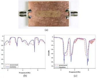
Figure 13. (a) Ground plane of the fabricated dual-band filter. (b) Measured and simulated S11 parameters. (c) Measured and simulated S21 parameters.
(a)
(b) (c)
4. CONCLUSION
A compact multi-band band-reject filter is proposed based on the multi-ring complementary split ring resonator (N-ring CSRR). Two filters are designed and simulated for two different cases (for N = 2 and 3). The desired number of the stopbands in the filter can be controlled by the number of the rings in one CSRR unit cell. A dual-band bandstop filter was proposed by etching four unit cells of two-ring CSRR in the ground plane of a microstrip line. On the other hand, a tri-band bandstop filter was designed by cascading four unit cells of three-ring CSRR. Moreover, the designed filters show a great flexibility. By choosing the geometric dimensions of the multi-ring CSRR cell appropriately, the center frequencies of the stopbands could be easily determined. The proposed filters were fabricated and tested. A good agreement between simulated and measured results validates the proposed design. The proposed filters provide a new way to design multi-band filters with small dimensions and simple structures. Moreover, the newly fabricated filters are suitable for WiMAX and WLAN applications.
ACKNOWLEDGMENT
The authors wish to acknowledge the valuable help of Traian Antonescu and David Dousset of Polytechnique Montr´eal for their assistance in fabrication and for the experimental measurements.
REFERENCES
1. Cui, T. J., D. R. Smith, and L. Ruopeng, Metamaterials: Theory, Design, and Applications, Springer Science & Business Media, New York, 2010.
2. Pendry, J. B., A. J. Holden, D. J. Robbins, and W. J. Stewart, “Magnetism from conductors and enhanced nonlinear phenomena,” IEEE Transactions on Microwave Theory and Techniques, Vol. 47, 2075–2084, 1999.
3. Smith, D. R., W. J. Padilla, D. C. Wier, S. C. Nemat-Nasser, and S. Schultz, “Composite medium with simultaneously negative permeability and permittivity,” Physical Review Letters, Vol. 84, 4184–4187, 2000.
4. Marques, R., F. Mesa, J. Martel, and F. Medina, “Comparative analysis of edge- and broadside-coupled split ring resonators for metamaterial design-theory and experiments,” IET Microwaves, Antennas & Propagation, Vol. 51, 2572–2581, 2003.
5. Garca-Garca, J. J., I. Gil, F. Martin, M. C. Velzquez-Ahumada, and J. Martel, “Efficient area reduction in microstrip crosscoupled resonator filters by using split rings resonators and spiral resonators,”35th European Microwave Conference (CCECE), 1235–1238, 2005.
6. Fan, J.-W., C.-H. Liang, and D. Li, “Design of cross-coupled dual-band filter with equal-length split-ring resonators,”Progress In Electromagnetics Research, Vol. 75, 285–293, 2007.
7. De Paco, P., O. Men´endez, and J. Marin, “Dual-band filter using non-bianisotropic split-ring resonators,”Progress In Electromagnetics Research Letters, Vol. 13, 51–58, 2010.
8. Zhou, L., S. Liu, H. Zhang, X. Kong, and Y. Guo, “Compact dual-band bandpass filter using improved split ring resonators based on stepped impedance resonator,” Progress In Electromagnetics Research Letters, Vol. 23, 57–63, 2011.
9. Fallahzadeh, S., H. Bahrami, and M. Tayarani, “A novel dual-band bandstop waveguide filter using split ring resonators,”Progress In Electromagnetics Research Letters, Vol. 12, 133–139, 2009. 10. Falcone, F., T. Lopetegi, J. D. Baena, R. Marques, R. Martin, and M. Sorolla, “Effective
stopband microstrip lines based on complementary split ring resonators,” IEEE Microwave and Wireless Components Letters, Vol. 14, 280–282, 2004.
12. Lai, X., Q. Li, P. Y. Qin, B. Wu, and C. H. Liang, “A novel wideband bandpass filter based on complementary split-ring resonator,” Progress In Electromagnetics Research C, Vol. 1, 177–184, 2008.
13. Khan, S. N., X. G. Liu, L. X. Shao, and Y. Wang, “Complementary split ring resonators of large stop bandwidth,”Progress In Electromagnetics Research Letters, Vol. 14, 127–132, 2010.
14. Li, M.-H., H.-L. Yang, H. Lin, and B.-X. Xiao, “Compact dual-band band-reject filter using complementary split-ring resonators,” Electronics Letters, Vol. 48, No. 10, 574–575, 2012.
15. Cao, H., S. He, H. Li, and S. Yang, “A compact wideband bandpass filter using novel CSRR loaded QMSIW resonator with high selectivity,” Progress In Electromagnetics Research C, Vol. 41, 239–254, 2013.
16. Che, W. Q., W. J. Feng, and K. Deng, “Microstrip dual-band bandstop filter of defected ground structure and stepped impedance resonators,”International Journal of Electronics, Vol. 97, 1351– 1359, 2010.
17. Woo, D.-J., T.-K. Lee, J.-W. Lee, and S.-H. Chao, “Novel U-slot and V-slot DGSs for bandstop filter with improvedQfactor,” IEEE Transactions on Microwave Theory and Techniques, Vol. 54, No. 6, 2840–2847, 2006.
18. Rehman, S. U., A. F. Sheta, and M. Alkanhal, “Compact band-stop filter using defected ground structure (DGS),” Saudi International Electronics, Communications and Photonics Conference, SIECPC, 2011.
19. Wang, J., H. Ning, L. Mao, and M. Li, “Miniaturized dual-band bandstop filter using defected microstrip structure and defected ground structure,” IEEE MTT-S International Microwave Symposium Digest, 1–3, 2012.
20. Xiao, J.-K. and Y.-F. Zhu, “New U-shaped DGS bandstop filters,” Progress In Electromagnetics Research C, Vol. 41, 179–191, 2012.
21. Turkmen, O., E. Ekmekci, and G. Turhan-Sayan, “A new multi-ring SRR type metamaterial design with multiple magnetic resonances,”PIERS Proceedings, 315–319, Mar. 20–23, 2011.
22. Smith, D. R., S. Schultz, P. Markos, and M. Soukoulis, “Determination of effective permittivity and permeability of metamaterials from reflection and transmission coefficients,” Physical Review B, Vol. 65, 1–5, 2002.
23. Chen, X., T. M. Grzegorczyk, B. I. Wu, J. Pacheco, and J. A. Kong, “Robust method to retrieve the constitutive effective parameters of metamaterials,” Physical Review E, Vol. 70, 1–7, 2004. 24. Baena, J. D., J. Bonache, F. Martin, R. M. Sillero, et al., “Equivalent-circuit models for split-ring