20th International Conference on Structural Mechanics in Reactor Technology (SMiRT 20) Espoo, Finland, August 9-14, 2009 SMiRT 20-Division III, Paper 1775
Simulating Dynamic Fracture in Oxide Fuel Pellets
Using Cohesive Zone Models
R. L. Williamson
aand D. A. Knoll
a aIdaho National Laboratory, PO Box 1625, Idaho Falls, ID 83415-3855, USA, e-mail: [email protected]
Keywords: fuel fracture, cohesive zone models, discrete cracking, dynamic fracture
1
ABSTRACT
Finite element cohesive zone (CZ) fracture methods are used to investigate dynamic crack behavior in oxide fuel pellets during power-up, steady-operation, and power-ramping. Single-pellet models are developed in 2D (axisymmetric and plane strain) and 3D, assuming nonlinear fully-coupled thermomechanical behavior. Cohesive surfaces are placed along potential crack paths, with the path orientation dictated by experimental evidence from irradiated pellets. Cohesive cracks initiate where the maximum principal stress reaches the fracture strength, and open as dictated by a prescribed traction-separation function. Softening behavior in the CZ constitutive law leads to numerical difficulties, requiring viscous regularization to achieve convergence. Sensitivity to meshing, iteration convergence tolerance, and viscous regularization is investigated. Predicted cracking patterns and crack interaction behavior are described. Radial and transverse fracture occurs during initial heating, with further cracking (including circumferential fracture) observed as temperature gradients increase during steady-operation and power-ramping. The stress field is strongly affected by fracture, becoming highly non-uniform after cracking. Results suggest that realistic fuel pellet fracture modeling will likely require a combination of discrete and smeared-crack models.
2
INTRODUCTION
It is well known that oxide fuels crack during the first rise to power, with continued fracture occurring during steady operation and especially during power ramps or accidental transients. Fractures have a very strong influence on the stress state in the fuel which, in turn, drives critical phenomena such as fission gas release, fuel creep, and eventual fuel/clad mechanical interaction. These phenomena carry important implications not only for subsequent fuel performance, but also for safety.
A variety of approaches are used to account for pellet fracture in fuel performance codes. The most common and simplest technique employs empirical relocation models, which simply force radial displacement of the fuel as a function of power and burnup. A few codes employ a more mechanistic approach, using smeared-cracking models to locally modify the material behavior and approximate the effects of fracture (Rashid, Dunham, and Montgomery 2004; Van Uffelen 2005; Michel et al. 2008). These models are reasonably straightforward to implement, since they do not involve the complexities associated with tracking of discrete cracks; only the local constitutive behavior in terms of stresses and strains is modified in any region which undergoes cracking. Recently, interest has been expressed in discrete fracture methods, such as the cohesive zone approach (Helfer et al. 2004). Such models are attractive from a mechanistic and physical standpoint, since they reflect the localized nature of cracking. The precise locations where fractures initiate, as well as the crack evolution characteristics, are determined as part of the solution. Cohesive zone models also offer the possibility to simulate important phenomena such as crack closure during power reduction and crack healing (re-sintering) in high temperature regions.
3
COHESIVE ZONE MODELS
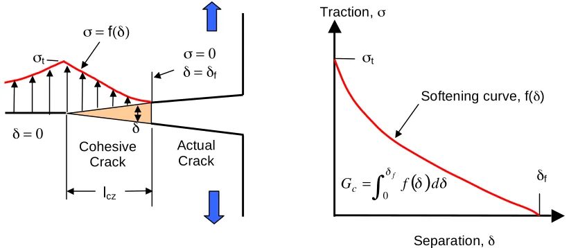
Cohesive zone (CZ) modeling, based on the original ideas of Dugdale (1960) and Barenblatt (1962), has become a well-established approach in computational fracture mechanics. CZ techniques have been used to model crack growth in a wide variety of materials (e.g., concrete, ceramics, metals, and polymers) as well as interfaces between materials (see Planas et al. 2003 for references). The CZ fracture process, in its simplest form, is shown schematically in Fig. 1. A cohesive crack initiates where the maximum principal stress σI
reaches the fracture strength σt, resulting in a crack oriented perpendicular to the principal stress direction.
After forming, the cohesive crack opens while transferring stress from one crack face to the other, as dictated by a prescribed traction-separation function, f(δ), usually called the softening function or softening curve; δf
is the critical opening displacement at which the cohesive traction is reduced to zero. The softening function is typically characterized by two material properties: the fracture strength (σt) and cohesive fracture energy
(Gc). The fracture energy is the external energy required to create and completely break a unit surface area of
the cohesive crack, and is given by the area under the softening curve, as indicated in Fig. 1. The assumed shape of the softening function is a third variable in the constitutive description, and many different shapes have been tried. de Borst (2003) reports that for ductile fracture, the effect of the assumed shape is typically less important than σt and Gc, however, for brittle decohesion, the shape plays a bigger role, and is sometimes
even more important than the fracture strength.
Figure 1. Schematic of the cohesive-zone fracture process.
The softening behavior in the constitutive law can often lead to numerical difficulties, including mesh sensitivity, lack of convergence, and highly disparate time scales. Viscous regularization, which involves adding a small amount of viscous damping to the damage function, is oftentimes needed to achieve convergence, particularly for low toughness materials. These numerical issues will be considered in more detail below.
Powerful CZ modeling capability was recently included in the ABAQUS (2008) commercial finite element thermomechanics software, which was used for this investigation. In ABAQUS, one can specify CZ behavior using either cohesive elements (which typically have finite thickness) or cohesive surfaces. Although some experimentation was done with cohesive elements, surfaces were selected for this study since they include the capability to model heat transfer and contact following initial separation, and are easier to set-up, particularly in 3D.
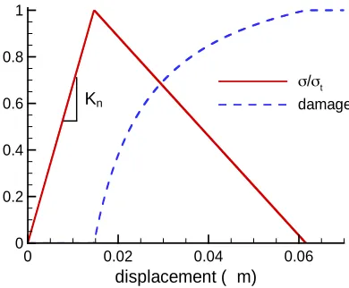
Before application to fuel pellet geometry and operating conditions, the ABAQUS CZ constitutive model was tested using a simple 2D two-element problem. The elements were bonded along their common face using a cohesive surface, and a simple linear softening curve was assumed. The stiffness of the elements (bulk material) was set artificially large to isolate the traction-separation behavior at the cohesive interface. Fracture properties typical for UO2, specifically a fracture strength of 130 MPa (Bailly, Menessier, and
Prunier 1999; Oguma 1983) and fracture energy of 4 J/m2 (Matzke, Inoue, and Warren 1980; Kutty et al. 1987), were specified. To overcome convergence difficulties, ABAQUS requires the cohesive surface have an artificial elastic stiffness (Kn) prior to any damage accumulation, which was set at 1.0x10
16
N/m3. The Separation, δ
Traction, σ
Actual Crack Cohesive
Crack σt
σ = f(δ)
σ = 0 δ = δf
δ δ = 0
Softening curve, f(δ) σt
δf
lcz
( )
! !!
d f Gc =
"
fshown in Fig. 2. Note that for the assumed triangular traction-separation function, the cohesive fracture energy is simply Gc = σtδf /2 (area under the curve), which, for the UO2 fracture properties specified above,
yields δf = 0.0615 µm. The ABAQUS computed traction-separation function (Fig. 2) matches the initial
stiffness, fracture strength, and separation at failure, as expected.
Figure 2. ABAQUS computed traction-separation and damage functions for UO2.
4
APPLICATION TO FUEL PELLETS
The most common application of CZ models is to situations where, either due to symmetry or experimental evidence, the crack path is known in advance. In these cases, the mesh can be constructed such that the crack path coincides with element boundaries, and cohesive elements or surfaces are placed between continuum elements along the potential crack path. To permit a more arbitrary direction of crack propagation, cohesive zones can be placed between all continuum elements, as demonstrated by Xu and Needleman (1994). The approach taken for this study was to design the mesh and place cohesive surfaces along a few potential crack paths, as dictated by experimental evidence. Cross-sections of irradiated oxide fuel pellets show that cracking occurs predominantly along radial and transverse (perpendicular to the cylindrical axes) planes, with some circumferential cracking observed after a few thermal cycles (Bailly, Menessier, and Prunier 1999; Oguma 1983). For simplicity and computational efficiency, the pellet geometry was initially approximated in 2D. Fully-coupled thermomechanical behavior was employed, including the effects of thermal expansion and swelling due to fission products. Only mode 1 (tensile) fracture was considered, in all cases using the UO2 fracture properties and traction-separation function (Fig. 2) given in section 3.
4.1 Pellet models
A simple cylindrical fuel pellet geometry was assumed (no dishing or chamfer), having a diameter of 9.34 mm and height of 14 mm. Three geometrical approximations were considered, as shown in Fig. 3. The partition lines in each figure identify potential crack paths, where continuum elements were joined with cohesive surfaces. Second-order reduced-integration continuum elements were used in the 2D calculations and first-order fully-integrated elements employed in 3D. To investigate cracking behavior in various modes of operation, each simulation included three time periods: an initial rise from ambient conditions to a uniform power of 240 W/cm over 200 s, steady operation to a burnup of 67 MWd/kgU, and then a power ramp (50% over 30 minutes) and 12 hr hold. Heat is removed by convective cooling from the pellet radial free surface, assuming a convection coefficient of 5000 W/m2K and coolant temperature of 500 K.
A 2D axisymmetric model (Fig. 3a) was considered initially, and is clearly the simplest, since only transverse cracking is possible. Seven potential crack paths are included, permitting fracture into eight equal-sized pieces. During initial uniform heating, the largest axial stress (and first point to exceed the fracture strength) is on the radial free surface at the axial midpoint, as indicated in the figure. Attention was focused on the crack propagating from this point to gain insight into numerical issues such as mesh sensitivity and the effects of viscous regularization. Information gained here was used in subsequent models.
displacement (µm)
0 0.02 0.04 0.06
0 0.2 0.4 0.6 0.8 1
!/!t
A transverse slice through the pellet center was considered next, resulting in the 2D plane-strain model shown in Fig. 3b. This geometry represents a step-up in complexity, since both radial and circumferential cracking is possible. Potential crack paths were included to permit fracture into eight radial slices and four circumferential rings. Note that this geometry identifies an additional complexity with regards to computing crack initiation sites. For uniform heating, the maximum principal stress occurs at the pellet free surface, but is uniform around the pellet periphery. So, in theory, cracks will develop at the same time and along all radial crack planes, independent of how many potential planes have been included in the model. In reality, it is known that only a few radial cracks form since there is a stochastic component to the fracture process, with crack initiation sites affected by irregularities in the surface geometry or material properties, leading to local stress concentrations. To investigate this effect, the mesh was “seeded” with small flaws at the radial crack initiation points, simply by displacing the outermost radial node 20 µm inward. Then four separate calculations were run with flaws included at one, three, four, and all eight of the radial crack planes. Based on numerical sensitivity results from the axisymmetric model, the radial nodal spacing (Δr) was set at 0.036 mm and the viscous regularization at 10-4 for all simulations.
The 3D model is shown in Fig. 3c. Potential crack paths were included to permit combined radial and transverse, but not circumferential, fracture. Note that symmetry permits analysis of an eighth-section of the full fuel pellet. At this point, the 3D calculations are considered preliminary, mainly designed to demonstrate feasibility. For example, no crack “seeding” was included, thus initiation of radial cracks is expected to be either along all potential paths or, as it turned out, along a lesser number of paths and likely determined by numerical error.
Figure 3. Pellet geometries considered: (a) 2D axisymmetric, (b) 2D plane-strain, and (c) 3D with eighth symmetry. Partition lines identify cohesive surfaces, or potential crack paths through the pellet.
4.2 Material behaviour
The fuel material was assumed to be UO2 at 95% theoretical density. The Young’s modulus (E), Poisson’s
ratio, and thermal expansion coefficient were assumed constant at 219 GPa, 0.345, and 10.0 x 10⁻⁶ K-1, respectively, as given by Olander (1976). Temperature and burnup dependent thermal properties and fission product fuel swelling was included via ABAQUS user-defined subroutines.
The temperature-dependent thermal conductivity of unirradiated UO2 was defined using an empirical
equation suggested by Fink (2000), modified to account for the effects of irradiation and porosity using a series of multipliers, as outlined by Lucuta, Matzke, and Hastings (1996). The result is a significant reduction in thermal conductivity with irradiation, particularly at lower temperatures, as shown in Williamson and Knoll (2009). As with the conductivity, an empirical relationship from Fink(2000) was used to define the temperature-dependent specific heat. Swelling is included using empirical relations from the MATPRO material library (Allison et al. 1993). Both solid and gaseous fission product swelling is included as described in detail in Williamson and Knoll (2009).
z
r (a)
r
(b) r
(c) r
symmetry planes potential crack paths
4.3 Crack-face behavior
Once a crack forms, models are included to describe the mechanical and thermal behavior of interacting crack faces. Faces which come into contact, either due to crack closure or fragment motion, are assumed to transmit only normal compressive forces (no friction). Although with ABAQUS it is possible to specify that crack faces rejoin upon contact, crack healing was not included in this study.
Heat transfer between crack faces is important, particularly for circumferential cracking, which can inhibit radial heat flow from the pellet. Both radiant and conduction heat transfer is included at all crack faces. Radiant exchange is modelled using a standard Stefan-Boltzmann law, dependent upon the surface emissivities and a view factor. For the closely spaced gaps in this study, the view factor was assumed to be unity and the emissivity was set at a constant value at 0.8. Conduction is included by computing a gap conductance between interacting surfaces, kg/dg, where kg is the temperature dependent thermal conductivity
of the fill gas and dg is the evolving gap width. The fuel rod fill gas was assumed to be pure helium (no
fission gas effects) with the conductivity given by a kg = 0.00264(T) 0.71
(Allison et al. 1993), where T (K) is an average of the two crack face temperatures and kg has the units of W/mK.
5
RESULTS
5.1 Numerical sensitivity
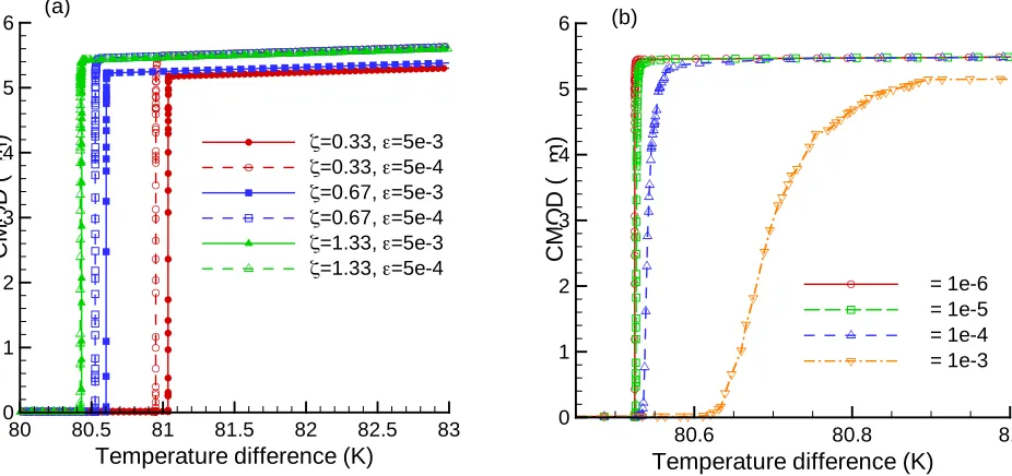
To assess numerical sensitivities, attention is first focused on the initiation and growth of the initial crack in the axisymmetric model (see Fig 3a). Figure 4 shows the computed crack mouth opening displacement (CMOD) vs temperature difference for various values of (ζ), a non-dimensional mesh parameter, (ε), the convergence criterion for the ABAQUS nonlinear Newton iteration, and (µ), a parameter controlling artificial viscous damping applied to the damage function (Fig. 2) to facilitate numerical convergence during material softening. Symbols are placed at each time increment to indicate the number of time steps required to simulate the crack growth process. In this figure and all results to follow, the temperature difference is measured between the fuel pellet centerline and outer surface, and is the driving force for crack growth. The mesh parameter ζ is given by lcz/Δr, where Δr is the nodal spacing and lcz is the length of the cohesive zone
(Fig. 1), approximated as lcz ~ EGc/σt 2
(Turon et al. 2007). Studies have shown that ζ should be on the order of three to achieve spatial mesh resolution (Turon et al. 2007), which, for the UO2 properties considered
here, requires fine meshing since lcz is on the order of 50 µm.
Figure 4. Computed crack mouth opening displacement (CMOD) vs. temperature difference for the initial crack in the axisymmetric model. Results in (a) show sensitivity to meshing and iteration tolerance and in (b) to viscous regularization. Symbols are placed at each time increment in the calculation.
Temperature difference (K)
C M O D ( µm )
80 80.5 81 81.5 82 82.5 83 0 1 2 3 4 5 6
!=0.33,"=5e-3 !=0.33,"=5e-4 !=0.67,"=5e-3 !=0.67,"=5e-4 !=1.33,"=5e-3 !=1.33,"=5e-4
Temperature difference (K)
C M O D ( µm )
80.6 80.8 81
0 1 2 3 4 5 6
µ= 1e-6
µ= 1e-5
µ= 1e-4
µ= 1e-3 (a)
Figure 4a shows the solution approaching spatial convergence as the number of radial quadratic elements is increased from 15 (Δr = 156 µm, ζ = 0.33) to 30 (Δr = 78 µm, ζ = 0.67) and then to 60 (Δr = 39
µm, ζ = 1.33). Although the finest mesh considered does not quite achieve the recommended ζ of three, either the 30 or 60 element simulations appears adequate for engineering accuracy. Since the length of the cohesive zone changes as the square of the fracture strength, a further check on spatial convergence was done by simply dropping the fracture strength in half and repeating the calculations on the existing meshes, providing solutions with ζ values of 1.33, 2.67, and 5.35. Although not shown here, solutions for the two finer meshes essentially overlaid. Note that Fig 4a also shows sensitivity to ε. Since the Newton iteration typically provides rapid convergence, the overall solution time is often not greatly increased by a 10x reduction in the iteration tolerance, and thus the tighter tolerance is probably warranted. The effect of viscous regularization on crack growth is shown in Fig. 4b. Since viscous damping is artificial, the goal is to improve the rate of convergence without compromising the results. For the specific case considered, a µ of 10-3 is clearly too dissipative, however, the solution with µ = 10-4 appears adequate for engineering calculations.
5.2 Axisymmetric model
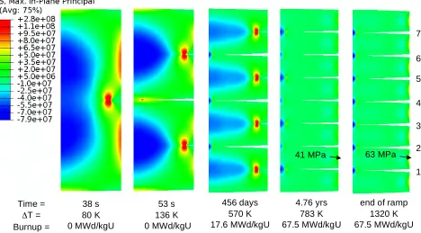
The computed maximum in-plane principal stress for the 2D axisymmetric model, showing predicted cracking behavior at various times in fuel life, is shown in Fig. 5. Cracks tips are easily identified by the focused high-stress regions. In the first three figures, plot times were selected just after crack initiation, and display rapidly propagating fractures. The first crack forms on the axial symmetry plane at a temperature difference of 80 K, resulting in significant local stress relief and a shift in the location of the peak stress along the pellet surface. A second set of cracks initiates at 136 K, resulting in a total of three transverse cracks at the end of pellet heat-up step. The final set of cracks is not observed until 456 days of operation, and occurs due to a gradual rise in the pellet temperature gradient due to reduced thermal conductivity with burnup. No further cracking is predicted during further steady operation as the temperature gradient continues to increase. As shown by comparing the two final plots, the power-ramp results in only a modest increase in stress at the pellet outer surface (41 to 63 MPa), and a slight increase in CMOD, even though the temperature difference increases substantially. Once fractured into eight pieces, very large temperature gradients are possible while the maximum principal stress remains well below the UO2 fracture strength.
Figure 5. Maximum in-plane principal stress (Pa) from the axisymmetric calculation, showing the predicted
cracking sequence. Displacements are magnified by 10x to better visualize fractures. 38 s
80 K 0 MWd/kgU
53 s 136 K 0 MWd/kgU
456 days 570 K 17.6 MWd/kgU
4.76 yrs 783 K 67.5 MWd/kgU
end of ramp 1320 K 67.5 MWd/kgU Time =
ΔT = Burnup =
41 MPa 63 MPa
1
1
2
1
4
1
5
1
6 1
1
7 1
1
3
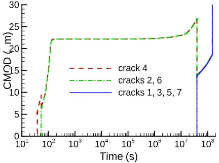
The fracture sequence is further illustrated in Fig. 6, showing the CMOD time history for all seven fractures. Note that cracks 2 and 6 (see Fig. 5 for crack numbers) result in a small and temporary closure of crack 4, but soon all three grow at the same rate and to the same CMOD. Of more interest is the partial closure of cracks 2, 4, and 6 once the final four cracks initiate. In this case, the three original cracks remain partially closed for long times (note the log time scale), raising the possibility of crack healing during operation. The figure also demonstrates the importance of an implicit variable time-step numerical algorithm, with computational time steps varying from microseconds, during rapid crack growth, to months, during steady operation.
Figure 6. CMOD versus time for all cracks predicted in the 2D axisymmetric model. Crack numbers are given in Fig. 5.
5.3 Plane-strain model
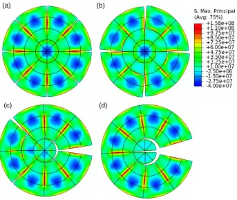
Figure 7 compares the maximum principal stress and predicted cracking behavior for the 2D plane-strain model at the end of the heat-up step, assuming crack “seeding” at eight, four, three, and one circumferential locations. The and 4-seed cases show symmetric cracking, as expected, with only radial cracking in the 8-seed case, but both radial and circumferential cracking in the 4-8-seed case. It is interesting that even a single crack results in immediate stress relief along the pellet periphery, with no further crack initiation from the outer surface. Instead, further radial and circumferential cracking occurs from inside the pellet. Note that the 1-seed results are invalid for a real fuel pin, since the large displacements shown (magnified 10x in the figure) would be impossible due to the constraint of the cladding. The results suggest, however, that an early single crack would likely close the pellet-clad gap non-symmetrically, significantly affecting the temperature field and any further cracking. Although not shown here, an additional calculation was done with the 8-seed model, however, the convective boundary was modified to produce nonuniform cooling around the pellet periphery. The non-axisymmetric temperature field in the pellet resulted in a single crack initiation point, and a crack pattern following initial heat-up similar to the 1-seed case.
Figure 8 illustrates further cracking in the 8-seed model, both at the end of steady-operation (Fig. 8a) and the end of the power-ramp step (Fig. 8b). Also shown is a time history (Fig. 8c) of the maximum principal stress at two points of interest (identified in Fig. 8a), during steady operation. From a comparison of Figs. 7a and 8a, it is evident that a band of circumferential cracks is predicted during steady operation due to increased thermal gradients resulting from thermal conductivity degradation with burnup. This cracking occurs shortly after 108 seconds, as indicated by the sharp stress drop at points A and B in Fig. 8c. The earlier and more gradual drop evident in the stress histories results from a gradual extension of the eight radial cracks. The stress histories are primarily shown to illustrate an inadequacy with the modeling approach. Note that, following initial circumferential cracking, the stress at point A is able to increase above the assumed fracture strength (130 MPa), since no potential crack path exists at this point. Thus instead of additional radial cracking, the stresses at both point A and B continue to rise until, during the power-ramp step (not shown), the stress at B reaches the fracture strength, and a second set of circumferential cracks occurs (Fig 8b). Without adding the complexity of additional discrete cracks, a simple solution to this problem might be to include a smeared-crack constitutive model to provide needed stress relief.
Time (s)
C
M
O
D
(
µm
)
101 102 103 104 105 106 107 108 0
5 10 15 20 25 30
Figure 7. Maximum principal stress (Pa) from the plane-strain model, showing predicted cracking for (a) 8-seed, (b) 4-8-seed, (c) 3-8-seed, and (d) 1-seed assumptions. Displacements are magnified by 10x to better visualize fracture.
Figure 8. Maximum principal stress (Pa) from the 8-seed plane-strain model, showing predicted cracking (a) at the end of steady-operation and (b) at the end of the power-ramp step. Displacements are magnified by 10x and the contour legend is given in Fig. 7.
5.4 3D model
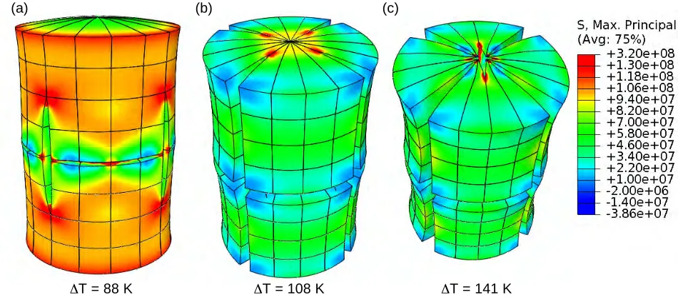
Figure 9 shows the maximum principal stress and predicted cracking behavior for the 3D model, at three times during initial heating. Fracture begins at a temperature difference of 88 K, with cracks forming in both the radial and transverse directions (Fig 9a). As the temperature difference increases, the radial cracks converge on the symmetry axis at the pellet top and bottom (Fig. 9b), and, with further heating, result in the formation of new radial cracks that propagate outward (Fig. 9c). As mentioned above, these results should be
Time (s)
M
a
x
p
ri
n
c
ip
a
l
s
tr
e
s
s
(M
P
a
)
0 5E+07 1E+08 1.5E+08
80 90 100 110 120 130 140
point A point B
A
B
(a) (b)
B
(c)
(a) (b)
considered preliminary, since they are for a reasonably coarse mesh (Δr = 0.24 mm) and do not include any crack seeding. They are mainly included here to demonstrate feasibility.
Figure 9. Maximum principal stress and predicted cracking behavior for the 3D model, at three times during initial power-up. Displacements are magnified by 200x.
6
CONCLUSIONS
Cohesive zone fracture modeling has been used to investigate progressive cracking in UO2 fuel pellets during
various stages of reactor operation. Conclusions from the study include:
• CZ models are attractive from a mechanistic and physical standpoint, since they reflect the localized nature of cracking. Such models permit exploration of a wide variety of phenomena including complex crack interactions and the effects of material properties and reactor operating conditions.
• The stress field in a fuel pellet is strongly affected by cracking behavior and very non-uniform after cracking.
• Although much can be learned using 2D approximations, fuel fracture is inherently 3D; important interactions between radial and transverse fractures cannot be captured in 2D.
• Although fracture of the brittle oxide fuel has a stochastic component, with crack initiation sites governed in part by surface flaws and material inhomogeneity, exploring cracking behavior based on an assumed number and location of initial flaws provides useful insight.
• Fuel fracture modeling is probably best done using some combination of discrete (e.g., CZ) and smeared cracking models. Discrete cracks are important for accurate prediction of pellet-clad mechanical interactions, but highly irradiated fuel contains far too many cracks (microcracking) to be described solely with discrete methods.
• Future modeling efforts should include the fuel cladding and fuel-clad gap to provide more realistic thermal behavior and permit detailed investigation of pellet-clad mechanical interaction.
• CZ fracture methods could be used to investigate the feasibility of employing “engineered flaws” in fuel pellet design. Controlled cracking could potentially result in improved fuel performance (e.g., enhanced thermal behavior, better fission gas control, or reduced pellet-clad mechanical interaction).
Acknowledgements. Work supported through the INL Laboratory Directed Research & Development
(LDRD) Program under DOE Idaho Operations Office Contract DE-AC07-05ID14517.
REFERENCES
ΔT = 88 K ΔT = 108 K ΔT = 141 K
ABAQUS. 2008. SIMULIA, Rising Sun Mills, 166 Valley Street, Providence, Rhode Island.
Allison C. M. et al. 1993. SCDAP/RELAP5/MOD3.1 Code manual volume IV: MATPRO. NUREG/CR 6150.
Bailly, H., Menessier, D., and Prunier, C. (ed.). 1999. The nuclear fuel of pressurized water reactors and fast reactors: design and behavior. Paris, France: Lavoisier Publishing. 642 p. ISBN CEA 2-7272-0198-2.
Barenblatt, G. I. 1962. The mathematical theory of equilibrium cracks in brittle fracture. Advances in applied mechanics. Vol. 7. P. 55-129.
de Borst, R. 2003. Numerical aspects of cohesive-zone models. Engineering fracture mechanics. Vol. 70. P. 1743-1757.
Dugdale, D. S. 1960. Yielding of steels containing slits. Journal of the mechanics and physics of solids. Vol. 8, P. 100-104.
Fink, J. K. 2000. Thermophysical properties of uranium dioxide. Journal of nuclear materials. Vol. 279. P. 1-18.
Helfer, T., Garcia, P., Ricaud, J. M., Struzik, C., Sidoroff, F., and Bernard, L. 2004. Modeling the effect of oxide fuel fracturing on the mechanical behavior of fuel rods. Pellet-clad interaction in water reactor fuels. Aix-en-Provence, France, March 9-11. ISBN 92-64-01157-9.
Kutty, T. R. G., Chandrasekharan, K. N., Panakkal, J. P., and Ghosh, J. K. 1987. Fracture toughness and fracture surface energy of sintered uranium dioxide fuel pellets. Journal of materials science letters. Vol. 6. P. 260-262.
Lucuta P. G., Matzke, H., and Hastings, I. J. 1996. A pragmatic approach to modeling thermal conductivity of irradiated UO2 fuel: Review and recommendations. Journal of nuclear materials. Vol. 232. P. 166-180.
Matzke, H., Inoue, T., and Warren, R. 1980. The surface energy of UO2 as determined by hertzian
indentation. Journal of nuclear materials. Vol. 91. P. 205-220.
Michel, B., Sercombe, J., Thouvenin, G., and Chatelet, R. 2008. 3D Fuel cracking modeling in pellet cladding mechanical interaction. Engineering fracture mechanics. Vol. 75, P. 3581-3598.
Oguma, M. 1983. Cracking and relocation behavior of nuclear fuel pellets during rise to power. Nuclear engineering and design. Vol. 76. P. 34-45.
Olander D. R. 1976. Fundamental aspects of nuclear reactor fuel elements. Springfield, Virginia: National Technical Information Service. 613 p.
Planas, J., Elices, M., Guinea, G. V., Gomez, F. J., Cendon, D. A., and Arbilla, I. 2003. Generalizations and specializations of cohesive crack models. Engineering fracture mechanics. Vol. 70. P. 1759-1776.
Rashid, Y., Dunham, R., and Montgomery, R. 2004. Fuel analysis and licensing code: FALCON MOD01. EPRI Report 1011308, Palo Alto, California.
Turon, A., Davila, C. G., Camanho, P. P., and Costa, J. 2007. An engineering solution for mesh size effects in the simulation of delamination using cohesive zone models. Engineering fracture mechanics. V. 74. P. 1665-1682.
Van Uffelen, P. 2005. Towards nuclear fuel modeling in the various reactor types across Europe with TRANSURANUS. Proceedings of the enlargement and integration workshop, Prague, Czech Republic, June 23-24.
Williamson, R. L. and Knoll, D. A. 2009. Enhancing the ABAQUS thermomechanics code to simulate steady and transient fuel rod behavior. Proceedings of Top Fuel 2009, Paris, France, September 6-10.