SOIL-STRUCTURE INTERACTION EFFECTS ON NUCLEAR
STRUCTURE FOUNDED ON LARGE PILE FOUNDATION
Peter Rangelow 1, Werner Schütz 2
1
AREVA Expert, PECC-G, AREVA GmbH, Offenbach, Germany
2
AREVA Advisor, PECC-G, AREVA GmbH, Offenbach, Germany
ABSTRACT
This paper presents results from an ongoing study on seismic soil-structure interaction (SSI) of a reactor building with a circular basemat supported by large number of concrete piles, performed within a seismic margin assessment (SMA) project. The objective of the study is to assess realistically kinematic and inertial interaction effects and to derive internal loads and floor-response spectra for the building structure. Transfer functions for the kinematic interaction motion (KIM) of the pile foundation for three different soil conditions are evaluated and compared with the free-field motion. Results derived by the subtraction method (SM) are verified by the modified subtraction method (MSM). Structure-soil-structure interaction (SSSI) effects with a neighboring building are also addressed through comparison of transfer functions for stand-alone and coupled modeling. Realistic evaluation of SSI effects on nuclear power plant (NPP) buildings supported by large pile foundations can substantially reduce over-conservatism in the design calculations and help identify additional seismic margin in a SMA.
INTRODUCTION
In a Seismic Margin Assessment the internal structural loads and floor-response spectra for the SMA Review Level Earthquake (RLE) have to be evaluated in order to establish a realistic seismic margin of the safety relevant structures, systems and components (SSC) over the Design Basis Earthquake (DBE) demand. The present paper summarizes results of SSI calculations of a reactor building with a circular basemat (diameter of ca. 50 m) supported by 430 concrete piles. The presented results are derived from ongoing extended analysis of the kinematic interaction motion at the bottom of the pile foundation cap (elevation -1.0 m) and from some preliminary inertial interaction calculations with a detailed 3D structural model. The analyses are performed with the SASSI2010 (2012) computer code.
CONFIGURATION OF THE PILE FOUNDATION AND SOIL CONDITIONS
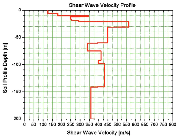
The shear wave velocity profile corresponding to the best-estimate shear modulus Gave for small strain –
established to a depth of -200 m – is shown in Figure 1. The alluvial soil consists of different types of cohesion-less sand, cohesive clay and mixtures thereof. The uncertainties in the soil properties are taken into account by considering three soil profiles: a) best estimate shear modulus Gave; b) minimum shear
modulus Gmin = 0.67 × Gave; and maximum shear modulus Gmax = 1.50 * Gave.
Figure 1. Best estimate shear wave velocity soil profile.
CONTROL POINT OF THE REVIEW LEVEL EARTHQUAKE SPECTRA
A recent probabilistic seismic hazard assessment (PSHA) study defines the site-specific hazard by a uniform hazard spectrum (UHS) at a hypothetical “Rock Outcrop” with shear wave velocity VS > 750. In
the present study a trial RLE is adopted with mean value ground response spectra for an annual frequency of exceedance of 10-4. The control point for the RLE spectra is assumed at a hypothetical outcrop surface at -800 m. Because of the lack of soil investigation data beyond the depth of 200 m, the soil properties between elevation -200 m and -800 m are assumed by analogy with the soil properties of another plant in similar geological conditions and by engineering judgment. Thus, in case of the best-estimate Gave soil
profile, the shear modulus increases linearly from the value at -200 m to a value corresponding to VS = 775 m/s at -550 m and is kept constant at this value to a depth of -800 m.
PERFORMED SITE-RESPONSE ANALYSIS
The aim of the site-response analysis is the evaluation of the iterated RLE strain-compatible shear modulus and damping ratio in the soil profiles as well as the ground motions within the soil column in the free-field at an elevation corresponding to the base of the pile foundation of the building, i.e. at -10m. Finally, both results – the iterated soil profiles and the ground motions (time-histories) at the base of the pile foundation – serve as input for the kinematic and inertial interaction analysis to be performed with the SASSI2010 (2012) program code for soil-structure interaction analysis. The site-response calculations – performed with the program SHAKE (1972) – take into account the nonlinear behavior of the soil material by using equivalent linear soil properties. An iterative calculation procedure is implemented to obtain values for shear modulus (G) and damping ratio (D) compatible with the effective seismic strain (!) in each layer. The G – ! and D – ! test curves necessary to that end are adopted from a recent geotechnical expert report.
SOIL-STRUCTURE INTERACTION ANALYSIS PROCEDURE
The SSI problem is most effectively analyzed using the sub-structuring approach. In this approach, the linear soil-structure interaction problem is subdivided into a series of simpler problems. Each sub-problem is solved separately and the results are combined in the final step of the analysis to provide the complete solution, based on the principle of (linear) superposition. For the case of structures with surface foundations, for which the structure and the foundation interface is located at the surface of the soil medium, the sub-structuring method is relatively simple. For structures embedded in the soil region or structures on pile foundations, the sub-structuring method becomes considerably more complicated. Conceptually, three types of solution methods are available depending on how the interaction degrees-of-freedom at the soil-structure interface are handled. These three types are: a) the rigid boundary method; b) the flexible boundary methods, and c) the flexible volume method. The flexible volume sub-structuring method is based on the concept of partitioning the total soil-structure system into two sub-structure systems. The first substructure consists of the original site, and the second substructure consists of the structure and basement (piles) minus the excavated soil, which is replaced with the basement. The substructures, when combined, form the original SSI system.
The SASSI2010 (2012) computer software adopts this flexible-volume method of sub-structuring. The program solves the equations of motion in the frequency domain and accounts for a horizontally layered half-space representing the soil region. The impedance matrix for the soil region is determined by inverting the foundation flexibility matrix. This matrix is calculated for the interaction nodes which are common to the structure and the soil region, based on displacements of a soil column located within the free-field and with a defined radius. This soil column is subjected to horizontal and vertical harmonic unit forces. The corresponding analysis is performed by using a consistent boundary at the border of the finite-element region. The impedance matrix is added to the stiffness matrix of the structure resulting in an overall complex matrix for all the degrees of freedom necessary to describe the behavior of the soil-structure system. This global matrix needs to be calculated and solved for a number of discrete frequencies in order to evaluate the transfer functions related to the free-field location where the seismic excitation is defined. The analysis is usually performed for about 50 ÷ 100 frequencies covering a frequency range up to 30 Hz. Transient motions are handled by applying the Fast Fourier Transform (FFT) techniques. Because the equations of motion are not solved for all the frequencies needed to perform the FFT, the values of the transfer functions which are in between the calculated ones are interpolated using a special interpolation scheme.
The SASSI2010 (2012) software provides two options for the calculation of the impedance matrix. The direct method (DM) assumes that all nodes of the flexible volume are interaction nodes. Practically, this method can be used only for relatively small problems with corresponding small number of interaction nodes. The calculation of the impedance matrix as the inverse of the flexibility matrix based on a large number of interaction nodes is a task that results in prohibitively extensive computation times and disk space, even for only few frequencies. The second option, called subtraction method (SM), reduces the impedance calculation to the degrees of freedom related to the outer boundary of the flexible volume. With this option, the size of the fully populated impedance matrix is reduced significantly to about 7500 x 7500 degrees of freedom for the present SSI problem. However, transfer functions calculated with this method should be carefully reviewed for unacceptable deviations in the frequency range of interest. The modified subtraction method (MSM) is an improvement of the subtraction method by including additional interaction nodes at the top surface of the foundation. The results of the modified subtraction method are used to validate the subtraction method results in the present study.
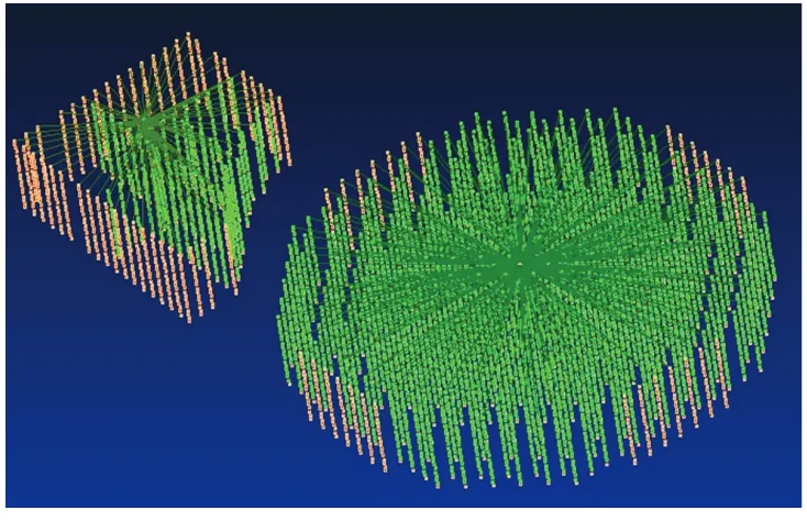
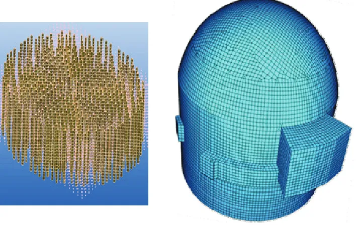
In order to evaluate the seismic response of the pile foundation, the soil region within the flexible volume is removed and then replaced together with the piles and the rigid pile cap. Mathematically, this is realized using brick and beam elements representing the excavated soil region (Figure 3) and piles (Figure 4). When establishing the overall matrix, the excavated soil elements are added with negative sign and the soil is replaced by special inter-pile elements accounting for the presence of the piles. The piles themselves are represented by beam elements. Their head is assumed to be fixed into the pile cap. Rigid beam elements (Figure 4) connect the center of the pile cap and the pile heads in order to calculate the dynamic response of the pile group.
The earthquake ground motion causes displacement in the soil known as free-field motion. In the case of embedded structures or pile foundations the soil will not follow the free-field motion. The inability of the foundation to match the free-field motion causes the kinematic interaction motion.
In the performed SSI analysis the kinematic interaction motion accounts for the existing pile foundation and is calculated for the pile cap which is assumed to be rigid and massless. Furthermore, it defines the seismic motion to which the building structure is subjected.
The mass of the pile cap is accounted for in the subsequent SSI calculations with the mass and stiffness of the building structure, where induced inertial forces cause further deformation in the soil, which is termed as inertial interaction.
PERFORMED KINEMATIC INTERACTION ANALYSIS
For SSI calculations with SASSI2010 (2012) the location of the free-field excitation can be specified either at the surface of the free-field or at an arbitrary elevation within the soil profile. In the current analysis, the seismic excitation is specified at the elevation of the pile toe within the free-field, i.e. -10 m. The necessary acceleration time histories are calculated with the program SHAKE (1972).
From the solution of the overall dynamic equations of motion for a number of frequencies the transfer functions can be evaluated. These functions represent the dynamic response of the total system related to the free-field. For the calculation of the kinematic interaction motion only the response at the center of the bottom of the pile cap is needed. The corresponding transfer functions for the horizontal direction and for the three soil conditions Gmin, Gave and Gmax are plotted in Figure 5 together with the transfer functions for
the free-field surface. The transfer functions look plausible in the frequency range of interest between 0.5 and 10 Hz. As expected, with increase of the soil stiffness the peaks of the transfer functions shift to higher frequencies. In comparison with the free-field motion, the peaks of the KIMs response are reduced due to the pile cap averaging and wave scattering effects.
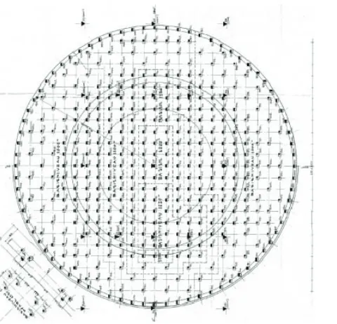
Figure 2. Configuration of the pile foundation.
Figure 3. Nodal points of the Flexible Volume (left) and Excavated Soil (right).
0.5 1 10 30 0
1 2 3 4 5 6 7 8 9 10 11
Free-Field Top G
minFree-Field Top G
aveFree-Field Top G
maxKIM G
minKIM G
aveKIM G
maxA
m
p
lif
ic
a
ti
o
n
F
a
c
to
r
Frequency [Hz]
Figure 5. Horizontal transfer functions between free-field input motion (-10 m, within soil column) and kinematic interaction motion at bottom of pile foundation cap (-1 m) and free surface (-1 m), respectively.
0.5 1 10 15 0
1 2 3 4 5 6 7 8 9
RB alone
NB alone
RB coupled
NB coupled
A
m
p
lif
ic
a
ti
o
n
F
a
c
to
r
Frequency [Hz]
Figure 7. Horizontal transfer functions between foundation input motion (-10 m, within soil column) and kinematic interaction motion at bottom of pile foundation caps (-1 m) of reactor building (RB)
and neighboring building (NB) for single (alone) and coupled model configurations.
0.5 1 10 20 0
1 2 3 4 5 6
SM MSM
A
m
p
lif
ic
a
ti
o
n
F
a
c
to
r
Frequency [Hz] Top of Basemat
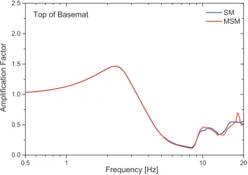
Figure 9. Transfer functions between foundation input motion (-10 m, within soil column) and the motion (kinematic + inertia) at top of reactor building basemat in horizontal X direction,
evaluated by the subtraction (SM) and modified subtraction methods (MSM).
0.5 1 10 20
0.0 0.5 1.0 1.5 2.0 2.5
SM MSM
A
m
p
lif
ic
a
ti
o
n
F
a
c
to
r
Frequency [Hz] Top of Basemat
Figure 10. Transfer functions between foundation input motion (-10 m, within soil column) and the motion (kinematic + inertia) at top of reactor building basemat in vertical Z direction,
0.5 1 10 20 0
1 2 3 4 5 6
SM MSM
A
m
p
lif
ic
a
ti
o
n
F
a
c
to
r
Frequency [Hz] Top of Building
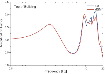
Figure 11. Transfer functions between foundation input motion (-10 m, within soil column) and the motion (kinematic + inertia) at reactor building top in horizontal X direction,
evaluated by the subtraction (SM) and modified subtraction (MSM) methods.
0.5 1 10 20
0.0 0.5 1.0 1.5 2.0 2.5
SM MSM
A
m
p
lif
ic
a
ti
o
n
F
a
c
to
r
Frequency [Hz] Top of Building
Figure 12. Transfer functions between foundation input motion (-10 m, within soil column) and the motion (kinematic + inertia) at reactor building top in vertical Z direction,
PERFORMED INERTIAL INTERACTION ANALYSIS
Because the generation of the site-specific 3D reactor building model is not completed, preliminary kinematic and inertial interaction analysis are performed with a detailed 3D model of a similar reactor building, see the right-hand half of Figure 8. The 3D structural model has about 60 000 nodes, 70 000 elements and 380 000 degrees of freedom. The model is buildup of thick shell elements, except for the thin shell elements of the containment structure (cylindrical and half-spherical structures) and the 3D stick elements of structural columns and beams. The total mass of the model is about 160 000 t.
In Figure 9 and Figure 10 the transfer functions between foundation input motion (-10 m, within soil column) and the motion (kinematic + inertia) at the basemat of the reactor building in horizontal X and vertical Z direction, respectively, evaluated by the subtraction and modified subtraction methods are shown. Similarly, Figure 11 and Figure 12 depict the transfer functions for the top of reactor building. Unacceptable deviations are not observed in the frequency range of interest between 0.5 and 10 Hz.
Figure 10 and Figure 11 indicate fundamental horizontal translational mode at about 1 Hz, rocking mode at about 3.5 Hz and vertical translational mode at about 2.5 Hz. The difference between the results for the Subtraction and Modified Subtraction methods at foundation level is negligible. Figure 11 confirms the expectation of motion amplification with increase of building height. Figure 12 points to significant vertical vibration modes between approx. 10 and 15 Hz. At this higher structural elevation the results for the subtraction and modified subtraction methods are very similar, except for the frequency range between 10 and 15 Hz where due to local vibration modes the difference is about 10 %. Since the spectral acceleration of the seismic demand in vertical direction in this frequency range is relatively small (expected for soft soil conditions), the effect on the response will be negligible.
CONCLUSION
In a seismic margin assessment the internal structural loads and floor-response spectra for the RLE have to be evaluated in order to establish a realistic seismic margin of the safety relevant structures, systems and components over the DBE demand. The present paper summarizes results of soil-structure interaction calculations of a reactor building supported by 430 concrete piles. The presented results are derived from ongoing extended analysis of the kinematic interaction motions at the bottom of the pile foundation cap and from some preliminary inertial interaction calculations with a detailed 3D structural model. The SSSI interaction between the reactor building and a smaller neighboring building is examined in terms of kinematic interaction. The corresponding transfer functions indicate that coupled modelling of both buildings reduces their peak response. Furthermore, the coupled modelling shifts the peak of the transfer function of the heavy structure (reactor building) to a lower frequency and the peak of the light structure to a higher frequency. Comparative results for the transfer functions evaluated by the subtraction and modified subtraction methods indicate negligible difference for both horizontal and vertical translations at foundation basemat level. At the top of the reactor building the results for the subtraction and modified subtraction methods are also very similar, except for the vertical response in the frequency range of approx. 10 to 15 Hz where the difference is about 10 %. Since the spectral acceleration of the seismic demand in vertical direction in this frequency range is relatively small (expected for soft soil conditions), the effect on the response will be negligible.
REFERENCES
SASSI 2010 (2012). “A Computer System for Analysis of Soil Structure Interaction”, University of California, Berkeley, USA.