DEVELOPMENT OF LAND BASED MOBILE MAPPING SYSTEM USING GLOBAL POSITIONING SYSTEM AND
CLOSE RANGE PHOTOGRAMMETRIC TECHNIQUES
WONG CHEE SIANG TONY
A thesis submitted in fulfilment of the requirements for the award of the degree of Master of Science (Geomatic Engineering)
Faculty of Geoinformation Science and Engineering Universiti Teknologi Malaysia
iv
ACKNOWLEDGEMENTS
In particular, I wish to express my sincere appreciation to my supervisor, Prof. Dr. Shahrum Ses and co-supervisor Dr. Anuar Ahmad for their encouragement, guidance, and friendship. Without their continue support and interest, this thesis would not have been the same as presented here.
A special thanks to Prof Dr. Halim Setan, for borrowing the digital camera and thanks also to the people from CIMES who help and giving support to my research.
I also wish to express my thankful to the following people whose have assisted me in the implementation of this research, which include Ms Chew May Yeen, Mr. Shu Kian Kok, Mr. Voon Min Hi, Mr. Kee Tuan Chew, Mr. Lim Wen Hong and Mr. Tan Wee Keng.
ABSTRACT
vi
ABSTRAK
TABLE OF CONTENTS
CHAPTER TITLE PAGE
THESIS STATUS DECLARATION
SUPERVISOR’S DECLARATION
DECLARATION ON COOPERATION WITH OUTSIDE AGENCIES AND CERTIFICATION OF
EXAMINATION
TITLE PAGE i
DECLARATION ii
DEDICATION iii
ACKNOWLEDGEMENTS iv
ABSTRACT v
ABSTRAK vi
TABLE OF CONTENTS vii
LIST OF TABLES xi
LIST OF FIGURES xii
LIST OF ABBREVIATIONS xv
LIST OF APPENDICES xvi
1 INTRODUCTION 1
1.1 Introduction 1
1.2 Problem Statement 2
1.3 Research Objectives 3
1.4 Research Scopes 4
1.5 Contribution 4
viii
1.7 The appliances 8
1.7.1 Mapping Sensor 9
1.7.2 GPS Receiver 9
1.7.3 PhotoModeler 9
1.7.4 Matlab 9
1.8 Research Methodology 10
1.9 Thesis Outline 12
2 CONCEPT AND THEORY 13
2.1 Global Positioning System 13
2.1.1 Concept of GPS Positioning 14 2.1.2 GPS Receivers Consideration 16
2.2 GPS Observation Techniques 17
2.2.1 Static Technique 18
2.2.2 Rapid Static Technique 18
2.2.3 Kinematic Technique 19
2.3 Geographical Information System 19
2.4 Photogrammetry 20
2.4.1 Rotation 21
2.4.2 Orientation 22
2.5 Coordinate Transformation 25
2.5.1 Two Dimensional Transformation 26
2.6 Terrestrial Photogrammetry 27
2.7 Mobile Mapping System 28
2.7.1 Georeferencing 30
2.7.2 Attribute Information in Mobile Mapping 32
2.8 Camera Calibration 33
2.8.1 Laboratory Calibration 33
2.8.2 On-the-job Calibration 35
3 SYSTEM DESIGN, SYSTEM CALIBRATION
AND FIELD PROCEDURE 37
3.1 System Design 37
3.1.1 Post Process Kinematic Positioning 38
3.1.2 Camera Position 38
3.2 Camera Calibration 39
3.2.1 Calibration Procedure 39
3.2.2 Camera Information 43
3.3 Field procedure 44
4 SOFTWARE AND IMAGE PROCESSING 46
4.1 PhotoModeler 46
4.1.1 Accuracy Factor 46
4.1.2 Project Setup 48
4.1.3 Camera Setup 49
4.1.4 Import Photographs 50
4.1.5 Marking and Referencing 51
4.1.6 Translation 52
4.1.7 Scaling 53
4.1.8 Rotation 54
4.1.9 Point Table 55
4.1.10 Export Coordinate 56
4.2 2D Transformation Program 58
5 RESULTS AND ANALYSIS 62
5.1 Camera Calibration 62
5.2 Distance Test 62
5.3 Baseline Test 65
5.4 Base map 67
5.5 Updating Road Database 69
x
5.7 Updating Building 75
6 CONCLUSIONS AND RECOMMENDATIONS 82
6.1 Conclusions 82
6.2 Recommendations 84
REFERENCES 85
LIST OF TABLES
TABLE NO. TITLE PAGE
2.1 Example of Available MMS 29
5.1 Camera Calibration Results 62
5.2 Accuracy Assessment of 5 meters 64 5.3 Accuracy Assessment in 10 meters 64
5.4 Accuracy Assessment in 15 meters 64 5.5 Accuracy Assessment in 20 meters 65
5.6 Result of Short Baseline 66
5.7 Result of Long Baseline 67
5.8 Four GPS Checkpoints established in the Study Area 67 5.9 Accuracy Assessment of Road Database 70 5.10 Accuracy Assessment of Road Sign Project 72 5.11 Accuracy Assessment of 5 meters Baseline 78 5.12 Accuracy Assessment of 12.7 meters Baseline 78 5.13 Accuracy Assessment of 22 meters Baseline 78
xii
LIST OF FIGURES
FIGURE NO. TITLE PAGE
1.1 Mobile Mapping System 3
1.2 Basic Concept of Mobile Mapping System 7 1.3 PhotoModeler, Digital Camera, GPS Receiver and Matlab 8
1.4 Flow Chart of Research Methodology 11
2.1 Principle of Satellite Positioning 15 2.2 The Intersection of Surface of Position
based on Range Measurement 17
2.3 Sequential Rotation of Axes in Three Dimensional Spaces 22
2.4 Object Coordinate System 22
2.5 Image Coordinate Frame in Object Coordinate System 23 2.6 Relationships between Different Coordinate System 31 2.7 Laboratory camera calibration in this research 34
3.1 System Design 37
3.2 System Configuration 38
3.3 Calibration Grid 40
3.4 Camera Calibration Project 42
3.5 Processing Finished Dialog Box 43
3.7 Mobile Mapping System in Study Area 44 3.8 System Configuration during Data Acquisition Phase 45
4.1 Accuracy Factor 47
4.2 Set up New Project 48
4.3 Measurement Unit 49
4.4 Camera Review 49
4.5 Import Images 50
4.6 Marking Points in the Middle Image 51 4.7 Marking Points at the Left Angle Image 52
4.8 Setting up the Coordinate 53
4.9 Assigned Camera with Translation Coordinates 53
4.10 Setting up the Scale Factor 54
4.11 Two Cameras are assigned with Scale 54 4.12 X-axes and Z-axes are defined in the Image 55 4.13 Quality Assessment of the Points 56
4.14 Cameras Position 57
4.15 Points Coordinate 58
4.16 Flow Chart of 2D Transformation Program 59
4.17 Program Interface 60
4.18 Import File to the Program 60
4.19 The ‘Quit’ button 61
5.1 Distance Test 63
5.2 Check Points of Distance Test 63
5.3 Set up of Camera Baseline 66
xiv
5.5 Four GPS Checkpoints of Study Area 68
5.6 Road Database Project 69
5.7 Image of Road Database Project 70
5.8 Road Sign Project 72
5.9 Road Sign in Base Map (scale 1:3900) 73 5.10 Qualitative Accuracy of Road Sign Project (scale 1:300) 73 5.11 Bus Stop in Base Map (scale 1:3900) 74 5.12 Qualitative Accuracy of the Bus Stop Project (Scale 1:300) 74
5.13 Updating ‘Building A’ Project 75
5.14 Image of Building for Part 1 76
5.15 Image of Building for Part 2 76 5.16 Image of Building for Part 3 77 5.17 Location of Check Point 3 in the Image 77 5.18 Building A in Base Map (scale 1:2300) 79
5.19 Updating ‘Building B’ Project 79
5.20 Building B 80
LIST OF ABBREVIATIONS
cm Centimetre
DOP Dilution of Positioning
DSMM Department of Survey and Mapping Malaysia DTM Digital Terrain Model
GIS Geographical Information System GLONASS Global Satellite Navigation System GPS Global Positioning System
Hz Hertz
Km Kilometre
m Metre
mm Millimetre
OTF On-the-fly
ppm Part per million
PPK Post Processed Kinematic PRN Pseudo Random Noise RMS Roof Mean Squares RSO Rectified Skew Orthomophic RTK Real Time Kinematics TGO Trimble Geomatics Office WGS84 World Geodetic System 1984
3D Three Dimensional
xvi
LIST OF APPENDICES
APPENDIX TITLE PAGE
A SPECIFICATIONS OF DIGITAL CAMERAS 90
B SPECIFICATIONS OF GPS RECEIVERS 96
C CAMERA CALIBRATION PROJECT FOR
KODAK DC290 AND CANON S400 101
D RESULTS OF ROAD NETWORK AND
BUS STOP PROJECTS FROM TGO 104
E POINTS REPORT OF ROAD SIGN,
BUS STOP AND BUILDING PROJECTS 108 F COORDINATE CONVERSION PROJECT
CHAPTER 1
INTRODUCTION
1.1 Introduction
The last two decades have shown an increasing trend in the use of Global Positioning System (GPS) technology in several applications in Malaysia. Such applications include land vehicles and automated car navigation, GPS-equipped KLIA limousines, land deformation monitoring and marine survey job which currently applied both in private and government sector.
The development of Mobile Mapping System (MMS) is still at initial stage in Malaysia. The research in MMS has been carried out since the first prototype introduced by the Center of Mapping at The Ohio State University (Bossler et.al., 1991). This system integrates navigation sensor such as GPS, Inertial Navigation System (INS) and mapping sensor such as Charge Coupled Device (CCD) camera.
2
1.2 Problem Statement
The conventional method of mapping such as aerial photography and field survey are coupled with the use of different remote sensing method. Basically, the data are integrated within a Geographic Information System (GIS) environment. Limitation of traditional land-based surveying systems is that each point of interest (i.e control point) needs to be occupied. The analysis of remote sensing data includes both optical and radar images. The processing of these conventional methods is more difficult, time consuming and costly. The use of digital camera is advantageous because it eliminates the requirement to scan photograph and it would substantially reduce the period from raw data collection to extracted data dissemination.
In MMS, direct georeferencing is done by using GPS and INS to locate the camera position and orientation. This is fundamentally different from traditional indirect georeferencing whereby the position and orientation of the platform are determined using measurements made to control points.
The control points are established through a field survey prior to or after data acquisition, and their establishment is typically expensive and time-consuming. Therefore, eliminating such step results in apparent decrease in both the cost and time required for data collection. The task of establishing ground control is much more complicated since its cost and time requirement are basically difficult to estimate. In many terrestrial surveys the establishment of sufficient ground control is virtually impossible, for example to consider the control requirement to map an entire city using close range photogrammetry. The establishment of ground control is not practical unless direct georeferencing is performed.
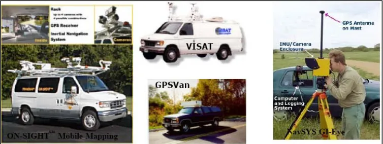
Figure 1.1: Mobile Mapping System (Zhang and Xiao, 2004)
Cartography and GIS have gain increases popularity in modern days. This new situation requires spatial database. Modern data requirements necessitate distinct solutions for acquisition of spatial information. The growing use of GIS technology and the consequent necessity to update information increases the importance of an environment to handle spatial data and information that will be even more demanding. An efficient electronic deposit of a large quantity of road images obtained by the mobile system is envisaged, whereby an image database is required to manage growing volume of data and images (Fernando and Silva, 2003).
1.3 Research Objectives
The objectives of this research include the following:-
i. To geo-referenced the geographical features of the digital image using GPS, digital camera comprise with the usage of a photogrammetric software, known as PhotoModeler.
4
1.4 Research Scopes
The research scopes of this study include the following:-
i. Camera calibration in the laboratory.
ii. Familiar with the Post Process Kinematic GPS technique and close range photogrammetry technique.
iii. Develop a program to integrate between the camera position and GPS coordinates.
iv. Accuracy test on Post Process Kinematic GPS technique. v. Updating base map from digital image.
vi. Evaluate the effectiveness of integration between digital camera, software and GPS.
1.5 Contribution
The aim of this research is to evaluate the effectiveness of GPS and photogrammetry in developing land-based mobile mapping system. Hopefully the outcome of this research is useful and can be implemented in Malaysia. The MMS is deemed to be more comprehensive and innovative in the future.
1.6 Literature Review
The mobile mapping technology has been developed since 1980’s. The development of the mobile mapping system became possible due to the availability of GPS signal for the civilian community.
collectors are getting smaller, lighter, and less expensive. The GPS and GIS software has become cheaper and easier to learn. All these advancements have made the GPS/GIS data collection tasks easier, faster and more economical.
Each GPS satellite transmits signal on two frequencies: L1 (1575.42 Mhz) and L2 (1227.60 Mhz). The L1 frequency contains the civilian Coarse Acquisition (C/A) Code as well as the military Precise (P) Code. The L2 frequency contains only P code. The P code is encrypted by the military which are using a technique known as anti-spoofing and is applicable to authorized personnel only. The encrypted P code is referred to as Y code. Civilian GPS receivers use the C/A code on the L1 frequency to compute positions, although high-end survey grade civilian receivers use the L1 and L2 frequencies’ carrier waves directly. Military GPS receivers use the P (Y) Code on both L1 and L2 frequencies to compute positions (Rizos,1999).
GPS receivers need at least three satellites to determine its position. Satellites position computation method is called trilateration. Recently, selective availability, an intentional degradation of the satellites signals, has been turned off down to centimeters or less, depending on equipment used and the conditions.
Undeniably, there may have particular uncertainties or errors, inherent in these positions. A number of factors that contribute to these errors include satellite clock drift, atmospheric conditions, measurement noise and multi-path. In addition, due to the satellite geometry, vertical accuracy (i.e elevation) generally can be one and a half to three times worse than horizontal accuracy.
6 Janeiro in 1984. Within ten years, digital close range photogrammetry has matured to the extent that it can now serve as a precise and reliable technique for non-contact three-dimensional measurement. The ease and speed of data acquisition, the inherent on-line and even real time capabilities, the high degree of automation and the adaptability to various requests have made it a viable measurement tool for a great number of different applications in science, art and industry (Akinson, 1996).
The position of a point in space is commonly defined by a three dimensional Cartesian coordinate system. The origin, scale and orientation can be arbitrarily defined. It is often necessary to convert between coordinates in systems having different origins, orientations and possibly scale (Akinson, 1996). In other words, it is required to define coordinated points with reference to a coordinate datum related to features on the object itself. Subsequently it may be required to define the points to a new datum.
Mobile Mapping System (MMS) is capable of observing objects at closer range, thus providing greater details. Land-based MMS uses digital camera as imaging sensor. This was possible because of the much smaller camera-to-object distance in land-based MMS when compared to air-borne systems. The poor resolution of CCD chips revealed that they could not be used in aerial applications without noticeable accuracy degradation (El-Sheimy, 1996). The use of digital camera is an advantageous because it eliminates the requirement to scan photographs. Consequently they substantially reduce the period from raw data collection to data dissemination.
The strength of MMS lays on the ability of georeferencing the mapping sensors. A mapping sensor is georeferenced when its position and orientation relative to mapping coordinate system is known. Once georeferenced, the mapping sensor can be used to determine the position of external points to the platform in the same mapping coordinate system. MMS differ from the traditional georeferencing where the position and orientation of the platform are determined using measurements made to control points. Establishment of control points are time consuming and labour intensive.
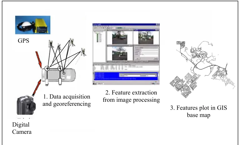
GPS
2. Feature extraction from image processing 1. Data acquisition
and georeferencing
3. Features plot in GIS base map Digital
Camera
Figure 1.2: Basic Concept of Mobile Mapping System
8 Completion of data acquisition, the images and navigation data from the INS and GPS sensor are downloaded to a personal computer. INS and GPS data are processed couple with digital images towards georeferenced with the aid of appropriate software. Finally, using photogrammetric principles, two or more georeferenced digital images, 2D and 3D positions of any point or object that is visible in the two or more images can be depicted.
1.7 The appliances
Figure 1.3 shows the instrumentation that used in this research. Instrumentation used includes digital cameras (Kodak DC290 and Canon S400) and GPS receivers (Trimble and Leica). Image processing is carried out using photogrammetry software known as PhotoModeler. On the other hand, Matlab are used for programming purpose.
1.7.1 Mapping sensor
For mapping sensor, Kodak DC290 and Canon S400 zoom digital camera are used in this research. The specifications of the camera are shown in Appendix A.
1.7.2 GPS Receiver
Positions of the mapping vehicle and cameras are determined using GPS Trimble 4800 and Leica GPS System 500. The specification of the GPS receivers are shown in Appendix B. Post Pocessing Kinematic (PPK) technique is adopted to optimise the field task. Processing of the GPS data are carried out using Trimble GPS processing software known as Trimble Geomatic Office (TGO).
1.7.3 PhotoModeler
PhotoModeler is a close range photogrammetric software developed by EOS System. It is windows based which is capable of extracting measurements and constructing 3D models from digital images (EOS, 2006).
1.7.4 Matlab
10
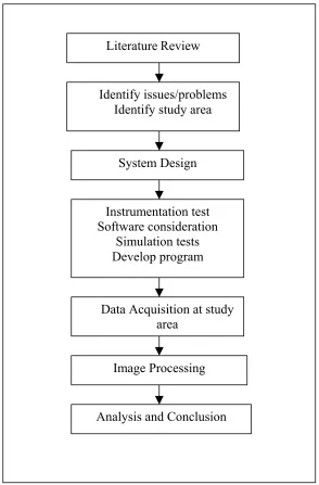
1.8 Research Methodology
Figure 1.4 shows the research methodology. Research methodology includes the followings:
i. Literature Review
The literature review is the backbone of the research. Information about Global Positioning System, close range photogrammetry, mobile mapping system and GIS are reviewed.
ii. System Design
The instruments that include in this research are GPS, CCD cameras, car and processing software, Photogrammetry.
iii. Instrumentation Test
Instrumentation test is carried out to make sure the instruments can applied effectively to the system. The tests are includes accuracy test on Post Process Kinematic GPS technique, camera calibration, software consideration and developed a 2D coordinate transformation program.
iv. Data Acquisition
The topographical features of study area are captured with the developed mobile mapping system.
v. Image Processing
vi. Analysis and Conclusion
At this stage, the anticipated finding will be derived from the analysis of the research. The conclusion is based on findings and experienced gain.
LiteratureReview
Identify issues/problems Identify study area
System Design
Instrumentation test Software consideration
Simulation tests Develop program
Analysis and Conclusion Data Acquisition at study
area
Image Processing
12
1.9 Thesis Outline
This thesis is divided into six chapters:-
i. Chapter 1: Introduction
This chapter discussed on the topic being studied such as issues and problems, research objectives, scope of study, significance of study, and research methodology.
ii. Chapter 2: Concept And Theory
The related theories are briefly discussed in this chapter. The discussion is focus on definition, concept about GPS, close range photogrammetry, GIS, and mobile mapping system.
iii. Chapter 3: System Design, System Calibration and Field Procedure
This chapter discussed on instruments calibration, system design and field procedures.
iv. Chapter 4: Software and Image Pocessing
This chapter deals with the processing software used, developed program and data processing of the topographic details gathered from the study area.
v. Chapter 5: Results and Analysis
Analysis on the accuracy of the topographic details and the evaluation of the mapping devices are discussed in this chapter.
vi. Chapter 6: Conclusions and Recommendations
REFERENCES
Atkinson, K.B. (1996). Close Range Photogrammetry and Machine Vision.
Department of Photogrammetry and Surveying, University College London.
Bossler, J.D., Goad, C.C., Johnson, P.C. and Novak, K. (1991). GPS and GIS Map the Nation’s Highway. Geo Info Systems.
EOS System Inc. (2006). Photomodeler Pro5.0 Help. http://www.photomodeler.com
ESRI Corporation (2001). ArcUser: The Mag. for ESRI Software User. United States Of America.
ESRI Corporation (2003). ArcPad version 6.0.3. http://www.esri.com/arcpad
Ellum, C.M., El-Sheimy, N. and Novak,K. (2002). Land Based Mobile Mapping Systems. Photogrammetry Engineering & Remote Sensing, 68(1): 13,15-17 and 28.
El-Sheimy, N. (1996). The Development of VISAT-A Mobile Survey System for GIS Applications. UCGE Report #20101, Department of Geomatics Engineering,
The University of Calgary, Canada.
Faizah Binti Bakri (2001). Sistem Maklumat Tanah Taman Universiti:
Pembangunan Pangkalan Data Sosio-ekonomi. Bachelor Thesis, Faculty Geoinformation Science and Engineering, UTM.
86
Fraser, C. (1997). Digital Camera Self Calibration. ISPRS Journal of Photogrammetry & Remote Sensing, 52(1997): 149-159.
GIS Lounge (2006). What is GIS?.
http://gislounge.com/library/introgis.shtml GIS Development (2006). Overview of GIS.
http://www.gisdevelopment.net/tutorials/tuman006.htm
Gontran, H. (2000). A Mobile Mapping System for Road Data Capture via Single Camera. Swiss Federal Institute of Technology.
Habib, A.F. (2000). Quantitative Measures for The Evaluation of Camera Stability. University of Calgary
He, G. and Novak, K. (1992). Automatic Analysis of Highway Features from Digital Stereo Images. International Archives of ISPRS, 29, B3: 119-124.
Hofman,B., Lichtenegger,H. and Collins.J. (1994). Global Positioning System: Theory and Pratice. Springer Wien ,NewYork.
Jechev,D (1999). Close Range Photogrammetry with Amateur Camera. GIS Sofia Ltd, Bulgaria.
Jia Sheng-Ju (2003). Spatial Location on City 3D Modeling with Close Range Stereo Images. Tongji University Shanghai China.
Karara, H.M and Adams, L.P (1989). Non-topographic photogrammetry. 2nd Edition, American Society for Photogrammetry and Remote Sensing, Falls Church, Virgina.
Kazuya Aoyama, (2003). Efficient Calibration of Amateur Digital Camera and Orientation For Photogrammetric Application. Tokyo Denki University.
Leick, A. (2004). GPS Satellite Surveying. John Wiley & Sons, Third Edition. ISBN 0-471-05930-7, New York.
Manandhar, D. (2000). Georeferencing of Multi Sensor Range Data for Vehicle Born Laser Mapping System (VLMS). ACRS2000, The University Of Tokyo.
Marc, E. H. (2001). Programming in Matlab. Pacific Grove, California
Margherita, F. (2003). A Low Cost MMS Integrating GPS, Digital Compass And A Camera To The Direct Georeferencing Of Digital Images. University di Salerno, Italy.
Meng, X. (1999). Vehicle-borne Highway Geometric Alignments and Facilities Data Capture Using DGPS and GPS/GIS Integration. ION GPS'99, 1667-16674.
Mohd. Nor Said. (1999). Pengenalan Kepada Sistem Geoinformasi. Monograf, Faculty Geoinformation Science and Engineering, Universiti Teknologi Malaysia
Moffitt, F.H. (1980). Photogrammetry. Third Edition, New York.
Novak, K. and Bossle, J.D. (1995). Development and Application of the Highway Mapping System. Photogrammetric Record, 15(85),pp.123-134, Ohio State University,
Ooishi T., Yamada K., Takeda H. and Kawai T. (2002). Development of Simple Mobile Mapping System for the Construction of Road Foundation Data. PS WGII/1 Real Time Mapping Technologies, Tokyo.
Rafael, C.G., Richard, E.W. and Steven, L.E. (2004). Digital Image Processing Using MatLab. Upper Saddle River.
Rizos,C (1999). Principle and Practice of GPS surveying.
88 Rizos,C (1999). Chapter 1: The GPS System. University of New South Wales,
http://www.gmat.unsw.edu.au/snap/gps/gps_notes1.pdf
Li,R.X. (1998). Detection and Location of Objects from Mobile Mapping Image Sequences by Hopfield Neural Networks. The Ohio State University.
Li,R.X. (1999). Mobile Mapping- An Emerging Technology for Spatial Data Acquisition. The Ohio State University.
Seeber, G. and Wubbena, G. (1989). Kinematic Positioning with Carrier Phases and ‘On The Way’ ambiguity resolution. Proceedings of the Fifth International Geodetic Symposium on Satellite Positioning, Las Cruces, New Mexico, 13-17 March, pp. 600-609.
Sompoch P. (2001). Automatic Recognition and Location of Road Signs from Terrestrial Color Imagery. Map Information Center, Royal Thai Survey Department, Thailand.
Wells,D. (1987). Guide to GPS Positioning. Canadian GPS Associates.
Zhang,K.F. and Xiao,B.L. (2004). Current Status of Low Cost GPS and Mobile Mapping Systems. Department of Geospatial Science, RMIT University, Melbourne, Australia