University of Windsor University of Windsor
Scholarship at UWindsor
Scholarship at UWindsor
Electronic Theses and Dissertations Theses, Dissertations, and Major Papers
1-1-1981
A read-only-memory oriented implementation of the number
A read-only-memory oriented implementation of the number
theoretic transform butterfly unit.
theoretic transform butterfly unit.
Mahmood Akhtar
University of Windsor
Follow this and additional works at: https://scholar.uwindsor.ca/etd
Recommended Citation Recommended Citation
Akhtar, Mahmood, "A read-only-memory oriented implementation of the number theoretic transform butterfly unit." (1981). Electronic Theses and Dissertations. 6754.
https://scholar.uwindsor.ca/etd/6754
by
MAHMOOD AKHTAR
A- Thesis
Submitted to the Faculty of Graduate Studies Through the Department of Electrical Engineering in partial fu lfillm e n t of
the requirements fo r the Degree of Master of Applied Science a t the
University of Windsor
Windsor, Ontario, Canada
UMI Number: EC54737
INFO RM ATION TO USERS
The quality of this reproduction is dependent upon the quality of the copy
submitted. Broken or indistinct print, colored or poor quality illustrations
and photographs, print bleed-through, substandard margins, and improper
alignment can adversely affect reproduction.
In the unlikely event that the author did not send a complete manuscript
and there are missing pages, these will be noted. Also, if unauthorized
copyright material had to be removed, a note will indicate the deletion.
UMI Microform E C 5 4 7 3 7 Copyright 2010 by ProQuest LLC
All rights reserved. This microform edition is protected against unauthorized copying under Title 17, United States Code.
ProQuest LLC
789 East Eisenhower Parkway P.O. Box 1346
ABSTRACT
This thesis is concerned with, the design o f a hardware
implementation o f a Number Theoretic Transform b u tte rfly structure.
The b u tte rfly is being used as the computational element in a
Number Theoretic Transform processor suitable fo r d ig ita l signal
processing operations. The b u tte r fly has been realized using
arrays of read-only-memory (ROM), and table look-up techniques. A ll
mathematical operations performed by the Number Theoretic Transform
b u tte rfly have been carried out using the Residue Number System.
The; ROM oriented structure lends i t s e l f to an e ffic ie n t re a liz a tio n
using very large scale integration CVLSIl technology. The use of
high density EPROMS in a pip eline configuration results in a
structure suitable fo r real time signal processing applications.
Dr. W.C. M ille r fo r many valuable discussions and constructive
critic is m on th is thesis. I am also very thankful to Dr. G.A.
Ju llien fo r his advice and assistance throughout the study period.
Thanks are due to the other members of the Department and my fellow
graduate students, especially Mr. H.K. Nagpal who helped me in
various ways.
To my parents, I extend my sincere gratitude. Without th e ir
help and love, though fa r away, th is work would not have started.
Thanks are also due to Mrs. Marion Campeau fo r her diligence
in typing this thesis.
TABLE OF CONTENTS
ABSTRACT Ci)
ACKNOWLEDGEMENTS (_ii)
TABLE OF CONTENTS ( i l l )
LIST OF TABLES (V1)
LIST OF FIGURES
(vH)
CHAPTER 1 INTRODUCTION 1
1.1 Preamble 1
1.2 Number Theoretic Transform 1
1.3 The NTT B u tte rfly Unit 3
1.4 Objective and Outline of the Work 4
1.5 Thesis Organization 5
CHAPTER 2 LOOK UP TABLE IMPLEMENTATION OF RESIDUE ARITHMETIC 8
2.1 Introduction 8
2.2 Modular Arithmetic 8
2.3 Residue Number System 10
2.3.1 Representation of Numbers 10
2 .3 .2 Basic Arithmetic Operations in RNS 11
2 .3 .3 Conversion From RNS Using Chinese 13
Remainder Theorem
2 .4 Implementation of RNS Using Look Up Tables 17
2.4.1 Addition/Subtraction Using Sub-Moduli 20
2 .4 .2 M u ltiplicatio n Modulo A Prime Number 26
2.5 Summary - 30
CHAPTER 3 DIGITAL CONVOLUTION AND IMPLEMENTATION USING 32
TRANSFORM TECHNIQUES
3.1 Introduction to D ig ita l Convolution 32
3.1.1 F in ite Linear Convolution 32
3 .1 .2 Periodic or Cyclic Convolution 34
3 .1 .3 Linear Convolution via Cyclic 34
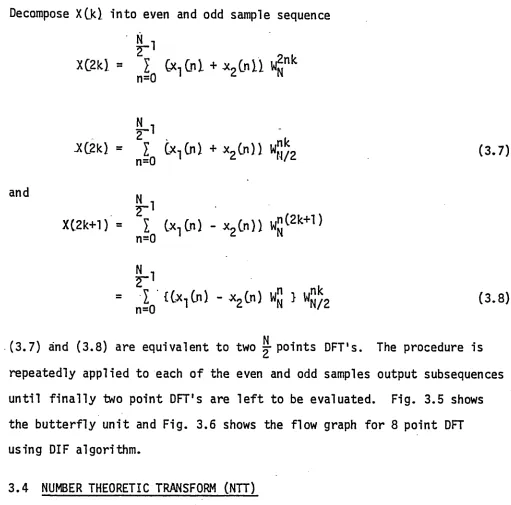
3.4 Number Theoretic Transform 42
3.4.1 In v e r t ib ilit y and Convolution 44
Property of NTT
3.5 Choice of the Parameters fo r the NTT 46
3.5.1 Transforms Defined Over Galois Fields 48
3.5 .2 Construction of Galois Fields GFCirf1) 50
3 .5 .3 Searching fo r the Generator a in 53
GF(m2)
3.6 NTT Using RNS Concepts 54
3.7 Summary 57
CHAPTER 4 IMPLEMENTATION OF AN NTT BUTTERFLY 61
4.1 Introduction 61
4.2 NTT Processor 62
4.2.1 Memory Structure 62
4 .2 .2 The B u tte rfly Unit 72
4 .2 .3 Efficiency of Primes 73
4 .2 .4 Selection of the Primes fo r Hardware 76
Implementation
4.3 ROM Realization o f B u tte rfly Structure 81
4.3.1 ROM Realization fo r 4n + 1 Primes 81
4 .3 .2 ROM Realization fo r 4n + 3 Primes 84
4.4 Simulation o f the B u tte rfly Structure 86
4.4.1 The Transform o f Real and Complex 90
Data fo r Both Primes
4 .4 .2 Upper Bound on Convolution 90
4 .4 .3 Simulation Results gg
4.5 Hardware Implementation of the B u tte rfly 99
Structure
4.5.1 Description of ICs Used 99
4 .5 .2 Generating and Storing the Tables 104
4 .5 .3 A Typical Pipeline Interconnection 107
4.6 Clock C irc u itry 116
4.8 Discussion on the Hardware Realization 120 of the B.F. Unit
4.9 Summary 124
CHAPTER 5 SUMMARY 126
CHAPTER 6 CONCLUSIONS 130
APPENDICES
t
A Simulation Programs 132
B Programs to Generate Table fo r Eprom, on Intel 220 157
REFERENCES . 184
2.1 Index o f the Elements Mod 11 27
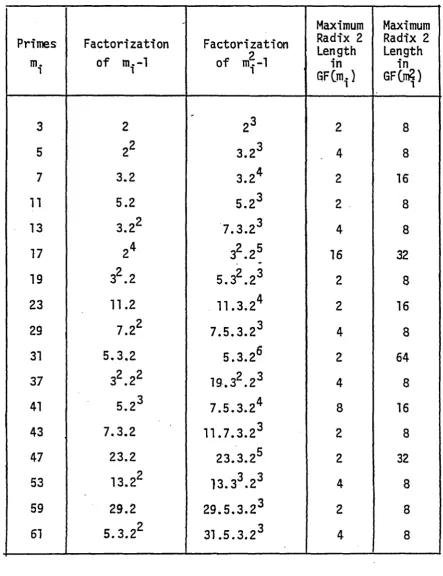
3.1 Table o f F ir s t Few Primes and the Associated 56
Transform Length
4.1 Comparison Between the Primes 76
4.2 Table o f Primes m- = 4n + 1 Less Than 9 B its 77
4 .3 Table of Primes m. = 4n + 3 Less Than 9 B its 78
4 .4 Requirements fo r Both Type o f Primes 84
LIST OF FIGURES
Figure Page
2 . 1 Pipeline Array fo r the Function ||a *b |+ |c *d ||
fo r 16 < m < 32 m
19
2 . 2 Modulo 9 Operations With Pre-M ultiplied Constant 21
2.3 Addition Modulo 19 Using 6 and 7 as Sub-Moduli 23
2.4 Addition Using Sub-Moduli Approach 25
2.5 M u ltiplication Using Index Addition and Sub-Moduli 29
2 . 6 M ultiplicatio n Using Index Addition Modulo 191 31
3.1 Explanation of Linear Convolution 33
3.2 Convolution Using OFT Method 37
3.3 2 Point B u tterfly (DIT) 41
3.4 Eight Point B u tterfly CD IT) 41
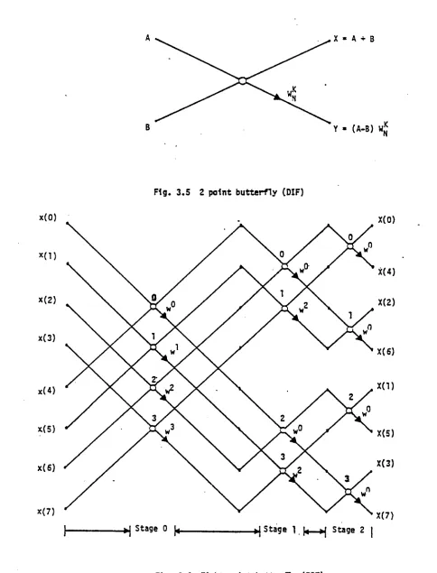
3.5 2 Point B u tte rfly CDIF) 43
3.6 Eight Point B u tte rfly CDIFl 43
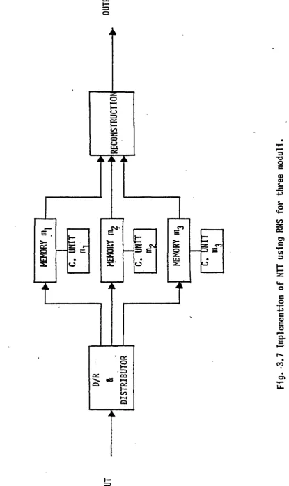
3.7 Implementation of NTT Using RNS fo r Three Moduli 58
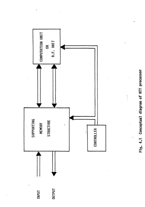
4.1 Conceptual Diagram of NTT Processor 63
4.2 Basic Machine Organization fo r 0100 66
4.3 Expansion of Transform Matrix fo r 0100 68
4.4 Flow Graph fo r an Eight Point 0100 Algorithm 69
4.5 An NTT Processor fo r 0100 Algorithm 70
4.6 An NTT Processor fo r Real Time 0100 71
4 .8 (a ) B u tterfly Unit fo r 4n + 1 Prime (n = even) 75
4.8(b) B u tterfly Unit fo r 4n + 1 Prime (n = odd) 75
4.9 Conceptual Diagram of B.F. Unit 82
4.10 Design o f NTT B u tterfly fo r 4n + 1 Prime (193) 83
4.11 Design of NTT B u tte rfly fo r 4n + 3 Prime (191) 85
4.12 Input and Transform of x(n ) 93
4.13 Convolution of Real Input 95-96
4.14 Convolution of Complex Input in GF(449 ) 97-98
4.15 Clock Pulses fo r the B u tte rfly Unit 100
4.16 Block Diagram and Pin Configuration of 2708 lkx8 Eprom 102
4.17 Logic Diagram and Pin Configuration of 8212, 8 b it 103
-Latch.
4.18 A Typical Pipeline Interconnection 108
4.19 Board 1 110 ,
4.20 Board 2 111
- 4.21 Board 3 112
4.22 Board 4 113
4.23 D ifferen t View of the Hardware Implemented B u tte rfly 115
4.24 Clock C irc u it fo r Pipeline Structure 117
4.25 Input-Output of the B u tte rfly Before-After Changing 119
One B it
CHAPTER 1
INTRODUCTION
1.1 PREAMBLE
This thesis describes a hardware re a liza tio n of a number
th eo retic transform b u tte rfly . The work. forms p art of a more general
-development of a d ig ita l signal processing f a c i l i t y th at is being
constructed by the signal and systems laboratory a t the University
o f Windsor. The authors re s p o n s ib ility in this project was to design
an NTT b u tte rfly that can be multiplexed with a memory support structure
to u ltim a te ly provide a d ig ita l f ilt e r in g ca p a b ility .
1.2 NUMBER THEORETIC TRANSFORM
F in ite d ig ita l convolution has many practical applications in
d ig ita l signal processing. I t can be used to implement non-recursive
d ig ita l f i l t e r s . I t can also be used to carry out auto and cross
c o rre la tio n , as well as, polynomial m u ltip lic a tio n . The d ire c t
✓
method of computing a convolution sum involves a number of m u ltip lication s
proportional to the product of the' length o f the two inputs [143.
M u ltip lic a tio n in a d ig ita l system, is a r e la tiv e ly slow operation
and. therefore techniques were investigated to minimize the number of
m u ltip lication s in the convolution sum. The use of transform
techniques to compute convolution is quite popular and the savings in
The ch aracteristic of these transforms ara such that the
convolution in time domain is equivalent to pointwisa m u ltip lication
in transform domain.
The discrete Fourier transform CDFT) is defined in the complex
number f ie ld and is one of the transforms that exhibits the cyclic
convolution property. The DFT is defined as
N-l -j.2ir/N.nfc. •
XQc) = I xCnl e , Ic = 0 , 1 , . . . ,N-1 U * U
n=0
The DFT becomes very a ttra c tiv e to use as i t can be implemented
e f f ic ie n t ly using the Fast Fourier Transform (FFT) type algorithm
[1 5 ]. The two main disadvantages associated with the FFT are the
m u ltip lic atio n by irra tio n a l co efficients and the inherent number
growth. Both o f the above introduce truncation and/or round-off
errors when implemented on a f in it e wordlength machine.
Pollard [4 ] has shown that transforms defined in a f in it e ring
also e x h ib it the c y clic convolution property. These transforms are
named as Number Theoretic Transforms (NTT) because number theoretic
concepts are used in th e ir d e fin itio n . The number theoretic
transform is defined as
N- 1 n l r
XCRL = | I *CnI a | k • 0 , 1 , 2 , . . . ,N-1 0 . 2 )
n=0 M
where a is the cyclic generator of order N. These transforms are
implemented using an integer number system. Since these transforms are
defined in f in it e rings, the number growth problem is inherently
3
convolution is within the defined range. Whenever the re su lt o f an
operation exceeds M, th e number is reduced modulo M and i f the
fin a l re s u lt is within the dynamic range, the intermediate overflows
can Be ignored. Thus the computation is exact and
truncation-roundoff errors do not a rise .
The proposed implementation of the NTT requires a supporting
memory structure and a computational unit commonly known as the
b u tte rfly unit CBFJ.- The operations performed by the b u tte rfly unit
are addition, subtraction and m u ltip lic a tio n , but no division. The
complexity of the BF unit depends upon the choice of the fie ld and
also the form of the generator, which is used to define the number
theoretic transform.
1.3 THE NTT BUTTERFLY UNIT
The binary operations in the BF u n it are performed modulo an
integer M, which is used in the d e fin itio n of the NTT. Modulo reduction
is not an easy operation unless the modulus M has a simpler form,
preferably a power o f two fo r the Binary number system implementation
o f the BF u n it. Radar [63 used the Mersenne number and Agarwal and
Burrus [73 used the Fermat numbers to ease o f the computation in
the BF u n it using the binary number system to perform the required
arithm etic operations modulo M. McClellan [163 has b u ilt hardware
fo r implementing the Fermat number transform and used adders-subtractors
to implement the BF u nit. The generator was chosen such that the
These adders-suhtractors and the h it s h iftin g were arranged tn a pipeline
configuration fo r a high, throughput ra te.
In using an array of ROMS, rather than adder-subtractor, e t c . , an
extremely simple structure emerges th at o ffers identical characteristics
fo r any required operation and is inherently simple to pipeline. The
use o f ROM arrays fo r implementing BF unit also relaxes the constraints
on the choice of the parameters fo r NTT and they can be chosen fre e ly
on purely number th eo retic basis to maximize the transform length.
1.4 OBJECTIVE AND OUTLINE OF THE WORK.
The use of NTT to compute convolution is very a ttra c tiv e because
o f it s e rro r fre e computation. The heart of the processor is the
computational u n it or the B u tte rfly u n it. The orientation in th is
.work, is to u t iliz e the advancement in memory fabrication technology
and build up a b u tte rfly unit using arrays of look up tables arranged
in a pip eline configuration. The look up table approach is quite a ttra c tiv e
because o f the fa c t th at m u ltip lication can be performed by
accessing the data from the tables and thus the m u ltip lication time
is reduced to the access time o f the ROMS.
Normally the dynamic range assocaited with an NTT processor would
be too large to allow an e ffic ie n t re a liza tio n based on table look, up
techniques. In th is work the Residue Number System has been employed
so th a t a problem w ith a large dynamic range can be converted to a number
of p a ra lle l operations with small dynamic ranges. In th is manner a r e a l
ization based on array of ROM is not only practical but desirable as i t
5
with memory fabrication.
The present work was divided into three phases. The f i r s t phase
of the work consisted of a lite ra tu re survey to establish the
theoretical basis fo r the design of the NTT processor. Pollard [4]
has defined transforms in f in it e rin g s /fie ld and has showed the cyclic
convolution property (ccp). of the transforms. Agarwal and Burrus [7]
have established the necessary conditions fo r the transforms to exh ib it
the ccp. Baraniecka [8] has proposed the look-up table approach using
the residue number system to implement the computational unit of
Number Theoretic Transform (NTT) processor. The use of look-up tables
relaxes the constraints on the choice of the parameters of the NTT.
Baraniecka [8] also outlined the procedure fo r selecting the NTT para
meters fo r look-up table implementation.
Pease [9] has presented a procedure fo r the design of the memory
organization of a FFT processor and Corinthois [ 1 0 ] - [ ll ] h a s used this
idea as the basis fo r a proposed memory organization fo r a FFT processor.
The same memory organization is used fo r the FNTT processor because of
the sim ilar structure of the two transforms.
The second phase of the work was to design a complete read-only-memory
oriented hardware implementation of the NTT B u tterfly u n it. The design
u tiliz e s the table look-up approach and employes a pipeline configuration.
A computer simulation of the hardware structure of the NTT bufferly and
the associated memory organization was carried out on the IBM 370/3031
f a c i li t y to v e rify the v a lid ity o f the proposed structure. The simulation
consisted of generating the look-up tables and then arranging them in the
selection of the parameters.
The fin a l phase of the work was to ac tu a lly build a prototype
computational unit using 2708 Eproms and 8212 as registers arranged
in a pipeline fashion. The registers are necessary fo r storing the
intermediate data to keep the pipeline f u l l . This unit was then
tested fo r real time application.
1.5 THESIS ORGANIZATION
Chapter 2 provides a review of the basic modular arithm etic
-used in the design. The advantage of using the RNS fo r a look-up
table implementation, especially fo r m u ltip lic a tio n , is established.
Binary operations using sub-moduli techniques are also described and
the implementation of addition-subtraction using look up tables is
shown. An e ffic ie n t way of performing m u ltip lication fo r large
primes is also described in th is chapter.
Chapter 3 starts with an introduction to d ig ita l convolution and
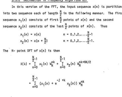
its implementation using transform techniques. Decimation in time
CDITl and decimation in frequency (DIF) forms of the FFT algorithm are
presented in d e ta il.
The choice of the parameter fo r the NTT and the construction of
the 2nd degree extension Galois fie ld s are reviewed. A suitable
choice of parameters fo r an RNS based implementation of the Number
Theoretic Transform is discussed.
The concept of an NTT processor is provided in Chapter 4. A
7
memory organization is suggested. The selection of the primes for
an e ffic ie n t hardware re alizatio n of the NTT b u tte rfly unit is
discussed and a fin a l design of the b u tte rfly structures for both
kind of primes ,is presented. These b u tte rfly structures were
simulated on an IBM 370 computer and the details of the simulation ,
are included in this chapter.
The b u tte rfly unit fo r 4n + 1 type primes was then implemented
in hardware using 2708 Eproms and 8212 latches. The sim plicity of
the structure using ROM arrays is obvious from the hardware design.
The generation of the look up tables on an In te l 220 system, and
the other relevant material is discussed, and the clock c irc u itry
fo r running the pipeline is given.
Chapter 5 summarizes the work presented in the thesis and
Chapter 6 presents the conclusions th at can be reached regarding this
2.1 INTRODUCTION
The look up ta b le approach o ffe rs the potential fo r a ROM oriented
high speed re a liz a tio n . This approach is p a rtic u la r ly advantageous in
re a liz in g m u ltip lic a tio n operations, which now become as simple and fa s t
as addition. The use o f the Residue Number System (RNS) to implement ad d itio n ,
subtraction and m u ltip lic a tio n in look up tables provides a great saving in
!
hardware and is more e f f ic ie n t than the BNS. The RMS is also an inherently
carry-borrow fre e system and does not introduce in te rn al delays due to
carry-borrow d ig it propagation.
In 'th is chapter a d e ta ile d discussion o f the residue number system
and it s implementation using look up tables is presented. The concepts
developed here w ill be applied to the number th e o re tic transform (NTT)
in the next chapter.
The residue number system is an integer number system and in the
i
following discussion, a l l the variables take on integer values only.
2 .2 MODULAR ARITHMETIC
I f two in te g e rs ,a and m,are re la te d by the follow ing equation
a = q . m + r (2.1)
where q and r are integers and r e 0 , 1, ____ _ m-1, then r
9
From eq. (2 .1 ) i t is clear that q is the quotient and r is the
le a s t positive remainder of — . m
D efin itio n 1: I f two integers have the same residue then they are
called congruent and represented as:
a h b mod m
such that
I a I = I b | = r
'm 1 'm
This also implies that (a-b) is d iv is ib le by m and w ritten as m |(a-b).
Thus a ll integers are congruent mod m to some integer in the f in it e set
( 0 , 1 , 2 , . . . ,m -l} and are said to belong to one o f the m classes. The
residue classes mod m form a commutative ring with id e n tity with respect to
modulo m addition and m u ltip lication and' is denoted by Z^. For example, i f
m=7,*there are seven d is tin c t classes and the integers belonging to these are
{0} = -1 4 , -7 , 0 , 7, 14,
{1}..= ... .. -13, -6, 1, 8, 15,
{2}..= ... .. -1 2 , -5 , 2 , 9 , 16,
( 3> = ... -1 1 . - 4 , 3, 10, 17, {4} = ... -10, -3 , 4, 11, 18, {5}..= ... ... - 9, -2 , 5, 12, 19,
{6}..= ... .. - 8, - 1 , 6, 13, 20,
e.g . 13 and 27 belong to the same class as | 13|^ = |27|^ = 6 or 13 = 27
mod 7.
The following basic arithm etic operations are permissible with
modulo arithm etic
(2 . 2 )
(2 .3 )
a) addition: 8 + 12 = 20 s 3 mod 17
b) negation: -7 s (-7 + 17 » 10) mod»-T2™-~
c) subtraction: 7 - 12 = 7 + ( -1 2) = (7 --M>-= -12) mod 17
d) m u ltip lic a tio n : 7 x 12 = 84 = 16 mod 17
e) division: ^-exists i f b has a m u ltip lic a tiv e inverse and
b divides a
2.3 RESIDUE NUMBER SYSTEM (RNS)
2.3.1 Representation o f Numbers
The representation of an integer in the residue number system
takes the form o f an n-tuple
a = (a-j, a2 , . . . , an) (2.5)
o f the least positive residue with respect to the set o f moduli
(m-j, , . . . , mn) . '
The residues, a^, are formally w ritten a.. = |a |^ . The residue
representation o f a number is unique. The converse of this statement
is true only i f the numbers considered are in the range of 0 to M-l
where
M = n m. (2 .6 )
i= l 1
and a ll the m.'s are re la tiv e ly prime. I f negative numbers are to be
represented in th is system, then the number range can be divided into
two parts. The f i r s t part represent positive numbers and second,
negative numbers.
11
x = +ve no i f x e {0,1 , 2
-ve no i f x e {£ , ! r + ^ • * • • > M -n
For M = odd
x = +ve no. i f x e {Q ,l , 2 9 • • •
-ve no. i f • • • 9 M -n
Example 1:
fo r n = 3
and m^ = 5; = 7; = 9
3
M = n m. = 5 . 7 . 9 = 315
- i= l 1
p ositive numbers e {0*1, . . . *157} f ”
negative numbers e {1 5 8 *...* 3 1 4 }
2 .3 .2 Basic A rithm etic Operations in the RNS
D e fin itio n 2: A binary operation defined on a set s of elements is
a ru le th a t assigns to each p a ir o f elements from s a unique element
from s.
D e fin itio n 3: A set s is closed with respect to binary operations i f
where a, b and c are any element in s and is the binary operation. The
residue number system is , in general, not closed under the binary operation of
division as the re s u lt o f division may not be an integer.
The residue number system is inh eren tly a carry/borrow free
system. The binary operations under which the system is closed can
be performed by independent operations on the respective d ig its , i . e . ,
Z = x □ y implies I . = |x . □ y.| (2 .8 )
where Q represents the allowed binary operations.
I t is useful to be fa m ilia r with the idea o f the m u ltip lic a tiv e inverse
before considering division in the residue number system.
Assume i t is desired to divide x by y in the real number system,
y y 1 1
then — can be w ritte n as ^ = x . — where — is the m u ltip lic a tiv e inverse
j y j j
o f y , and thus d ivision by y can be replaced by m u ltip lic a tio n with j .
I f ^ is not an integer in the real number system, then i t can
not be represented in the residue number system and division o f x by
y is not defined in the RNS. But fo r y an in te g e r, in other words, when
x is a m ultiple o f y , the idea o f a m u ltip lic a tiv e inverse can be used
to perform d iv is io n .
D e fin itio n 4: I f 0 < a < m and l ab |m = ^ e n a 1S ca^ e d the m u ltip lic a tiv e
inverse o f b. mod m and is denoted by a * |g jm .
The quantity |g |m exists i f and only i f (b,m) = 1 and |b |m i 0 .
In th is case |g |m is unique and division can be performed as
13
2.3.3 Conversion From RNS Using Chinese Remainder Theorem (CRT)
In th is section conversion from the RMS to any other number system is
discussed. This conversion is made possible using a theorem from number
theory [1 ] called the Chinese Remainder Theorem.
Given the residue representation (r -j, r 2 , . . . , r n) of x, the
Chinese Remainder Theorem makes i t possible to determine |x |^ , provided
the greatest common d iviso r of any p a ir o f moduli is one or moduli are
pairwise re la tiv e ly prime, l-xl^ is then given by the following equation:
III *
J J
The following example illu s tra te s the procedure to convert a
number from its residue representation using Chinese Remainder Theorem.
Example 2:
l e t m-j = 5, m2 = 7, = 9
3 ,
then M = H m. = 5 . 7 . 9 = 315
i= l 1
m-j = 63, m2 = 45, m^ = 35.
n r .
(2.10)
n
where M = n m .,
i= l 1
m. "i.
nu 2 45 7
'
i
3 '- 3 3 '= 1 = In = 8 since | 35
35 y
x 8|
Chinese Remainder Theorem
( x L ,= | in-, I — L + mo I == L +
M 1 1 1 r; 'm, 2 1 i 'm ,
m-j 1 *
-fi3 1
f
m3
o r
1 x l M= 1 63 . | r-j . 2 | 5 + 45 | r £ . 5 >7 +
Addition
moduli 5 7 9
x * 173 & 3 5 2
+y = 94 /| 3 4 +
|2 6 7 |315 = 267 ---2 1 6
using equation (2 .1 2 ) where ^ = 2 , ^ = 1 and r 3 :
|x |M = | 63.4 + 45.5 + 3 5 .3 |3]5 = 1582 J315 = 267
which is the correct re s u lt o f addition.
Subtraction
moduli 5 7 9
.x = 173 rt ? J 5W 2
-y = 94 /I 1 4
-(2.11)
315 (2.12)
15
using eq. (2.12) fo r (4 ,2 ,7 ) as (r-j»r2, r 3)
|63.3 + 45.3 + 3 5 .2| 315 = 79.
I f -ye nos. are also to be represented then the number range,
0 to 314, is divided as
0 , 1, 2 , . . . , 157 positive numbers
158, 1 5 9 , . . . , 314 negative numbers.
The following example explains the procedure when the re s u lt of
subtraction is-negative
moduli 5 7 9
x = 94 - - r * 4 3 4
-y = 173 — 1> 3 5 2
-79 - — o 1 5 2
using equation (2.1 2) , (1,5,2) ^ 2 3 6 since the resu lt lie s in the
negative number range, i t is a negative re s u lt therefore: subtract 315
from this^236 - 315 = -79 which is the correct re s u lt o f subtraction
in signed number representation.
M u ltiplica tio n
Choose the numbers such th at the re s u lt of m u ltip lication is
contained in the dynamic range
moduli 5 7 9
y = 6 1> 1 6 6 x
Division
x = 312 = (2 ,4 ,6 )
y = 13 = (3 ,6 ,4 )
F ir s t fin d the m u ltip lic a tiv e inverse o f y^'s
1
lml 1 3 I5
1 | = I 1 1
H 'm2 1 5 17
i | = 1 1 1
y3 3 1 4 '9
= 2 since | 3x2|g = 1
Division can now be performed by m ultiplying x..'s with m u ltip lic a tiv e
inverses o f y .'s
moduli 5 7 9
x = 312---- --- > 2 4 6
1 ^ 2 6 7 x
=--- o
y
312 using equation (2 .1 2 ), (4 ,3 ,6 ) -> 24 which is - y j •
To v e r ify th at division in RNS w ill not produce the closest integer value i f
x is not d iv is ib le by y , take
x = 311 = (1 ,3 ,5 )
y = 13 = (3 ,6 ,4 )
17
(2 ,4 ,8 ) - 242 f [£ ]r = 24
where [ .J R indicates rounding to nearest integer. Note that there
is no relation between ^7 and |£-| . The reason is quite obvious.
y y 315
^7
is not an integer and so |^-| has no meaning in the RNS. Twoy y 315
conclusions can be drawn from the above examples: ( i ) The RNS is not
a weighted magnitude representation. The residue representation does
not give any idea of magnitude and sign of the number represented.
( i i ) Division is not a simple operation. ( i i i ) Operations on a p air
of residues is independent of other residue operations.
2 .4 IMPLEMENTATION OF RNS USING LOOK UP TABLES
Recent advances in high density memory technology have made i t
possible to implement the RNS operations using look-up tables stored in
ROMS. The results of the operations can be precalculated and stored
in the locations addressed by the input data. Binary operations are
then reduced to the accessing of data from the stored tables. This is
p a rtic u la rly advantageous in m ultiplication which becomes as simple and
fa s t as addition. Speed of operation is then dependent only on the
access time of the ROMS.
For a given modulus, m. <. 32, the operation o f m u ltip lication and
addition modulo m. o f the two numbers can be computed by looking up
the re su lt in a Ik x 8 bits commercially available ROMS. Using the
same approach, operation moduli m-, 32 < m. <_64, would require a 4k x 8
bits ROM or four Ik x 8 b its ROMS and so on.
dynamic range. For example, with a wordlength of B b its , 2 numbers
p p OR
can be represented and therefore a to ta l of 2 . 2 = 2 entries are
required to store the re s u lt of operations in look up tables. For
n B
the same dynamic range, m.'s can be choosen such that n m. > 2 , then
2 1=1
each m. requires m. entries in the ta b le . Hence a to ta l of
n 2
£ m. entries are needed as compared to the d irec t implementation
i= l 1
or n p
which requires
2
n m. and fo r a reasonable value of n and m.'si= l 1 1
I m, 2 « 22B .
i= l 1
As an example o f an RNS implementation using look up ta b le , Fig. 2.1
illu s tr a te s a residue m u ltip lie r fo r modulo 31, followed by a
residue adder to implement the function | | a . b | 3-j + J c . d j3-j. The input
to each ta b le smodulo 31, can be represented by a maximum of 5 bits
and the to ta l o f the two inputs require ten address lin e s , the
output is fiv e bits and so commercially available Ik x 8 bits ROMS can
be used to implement th is function. A to ta l of three Ik x 8 ROMS and
two stages are required to compute the re s u lt. From Fig. 2 .1 , i t is
noted th a t ROM arrays o ffe r the p o s s ib ility o f easy pipelining fo r high
throughput. The data .from each ROM is latched and used as a p a rtia l
address fo r the next ROM. The only control function required is a latch
pulse. For every latch pulse, new input is accepted and a new output
is generated. The throughput rate o f the system is equal to the
19 (x )T A B L E lk x 8 R O M
i1 4
in ,
m £ fO _S JS CMcn
V I
V VO s-.0 ■o u -Q ft] z o
»—I
d z=3 LU L U z o >-< z z < ui z I—t z LU —I •
0 3 CM
C
r— co s •
x 0
*>< z z • r *
LU
in
Another advantage of the look-up table is that i t does not
require any extra hardware fo r addition or m u ltip lication with a
constant. The constant can be pre-m ultiplied or added and can be
stored along with the re s u lt of the operation.
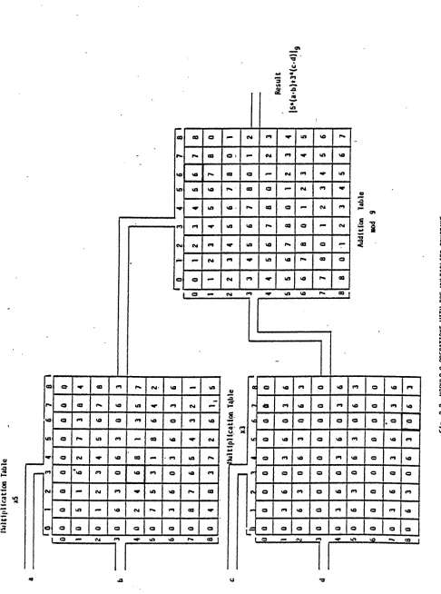
Example 3:
For modulus m = 9 compute
Z = | 5 |a . bI + 3 fc .d [ | with a=3, b=4, c=6 , d=8.
9 9 9
The re s u lt of the computation using residue arithm etic is 6. Fig. 2.2
shows the entries and the interconnections between the look up tables.
Two m u ltip lic atio n and one addition table is required to compute Z.
The f i r s t mil tip iic a tio n table generates the re s u lt o f m u ltip lication
p er-m ultiplied by 5, modulo 9, and second table generates the re s u lt of the
second m u ltip lic atio n pre-m ultiplied by 3, modulo 9. Note th a t
jn u Itip lic a tio n by 3 and 5 does not require any extra storage and does
not introduce any extra delay.
2.4 .1 Addition/Subtraction Using Sub-Moduli
As mentioned e a r lie r , commerically available ROMS can be used to
store tables fo r the RNS arithm etic, but this imposes an upper lim it
on the largest modulus to be used. To implement arithm etic modulo
m. < 32, Ik x 8 b its ROMS can be used, operation modulo 32 < m.. ^ 6 4
would require a 4k x 8 b its ROMS or four Ik x 8 b its ROMS and operation
modulo 64 < m. <, 128 would require 16k x 8 b its ROM or sixteen o f Ik x 8
b its ROMS and so on. As w ill be explained in the next chapter, prime
Il u ltl p H ca tlo n T a b le 21 u* CM CO CM 00 09 <n oo CSI MS uv oo o us os
o CM
US n
cm
oo o
us 1*1
00
cn
CM O CM m cn03 US CM cn o o
«o< <3 o o O O a
cn
© va
a US cn U9
o
o o
o o
o
cn o VO
o CM
us
X
03
O a o a o
o f sixteen or more ROMS does not seem a very e f f ic ie n t approach. In
order to increase the implementation e ffic ie n c y , the same technique
o f Breaking a large dynamic range in to sm aller moduli can be used to
implement the addition/subtraction modulo a large modulus. The
only constraints on the choice o f sub-moduli is th a t they should be
large enough to contain the re s u lt o f the operation modulo main
modulus and should be r e la tiv e ly prime. For example, i f main modulus
is m.j, then the maximum number which can occur is m.. - 1. The maximum
re s u lt o f addition is 2(m.. - 1) and therefore the sub-moduli should be
chosen such th at th e ir product is greater than 2(m. - 1 ). Mathematically
the condition can be represented as
ml i x m2i > 2 ^mi " ^ (2* 13)
where m^. and are the sub-moduli.
M u ltip lic a tio n can not be implemented e f f ic ie n t ly using the sub-moduli
approach as more than two sub-moduli are required to contain the re s u lt of
m u ltip lic a tio n , modulo the main modulus. However, fo r prime moduli, there
exists an e f f ic ie n t method to implement m u ltip lic a tio n u t iliz in g the •
sub-moduli approach and w ill be d e a lt with la t e r .
Fig. 2 .3 illu s tr a te s the addition modulo 19 using 6 and 7 as sub
moduli. F ir s t note th a t 6 .7 > 2 0 9 - 1 ) and so these are appropriate
sub-moduli, which w ill produce the correct re s u lt o f addition modulo 19.
This example is c le a rly not an e f f ic ie n t one as only one ROM would be
F ig . 2 .3 A D D IT IO N : ! I 19 U SIN G 6 an d 7 as S U B -M O D U L I © © o O
03
- CO on © CO 4k cn o
ro 4k On “■* 4k cn ©
u> on © ro cn o — ro
4> on m* ■ CO o - ro CO
o f\5 4k ro CO
SO
m
i/>os m
r -m cn © onm 4 * u> ro ~ eTI co ro —*
§
©
s
©CO fO —« o
R
r>
s -H g fOn ro CD in <0 ©
•o
CO © On ro 0» Mi
CO o ro 00
H i
CO 4k CO ID cn ro
.
cn ro o On CO CO
f •hJ «h4
CO cn 4k o On
*
OH
implementation using sub-moduli.
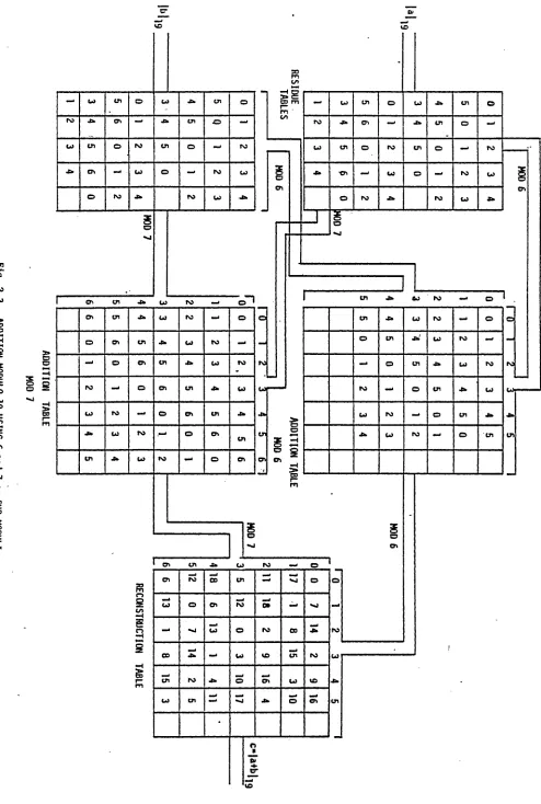
Example 4:
Assume Ik x 8 b its ROMS are av a ila b le to implement a d d itio n /
subtraction modulo 191. Numbers from 0 to 190 can be represented
by 8 b its and hence a to ta l o f 16 input (address) lines are required
and therefore the memory needed is 64k x 8 b its or 64 ROMS of Ik x 8
b its each. The maximum value o f the sub-moduli th at can be chosen
is 31 which have fiv e b it representation and the look up table w ill
require a to ta l o f 10 address lin es and so Ik x 8 ROMS can be used
to store the tab les. Fig. 2 .4 shows the implementation using sub
moduli 17 and 23, both have fiv e b i t representation. In the f i r s t
stage, the numbers to be added are reduced modulo 17 and 23. In the
next stage, addition modulo 17 and 23 is performed and in the fin a l stage,
the re s u lt is reconstructed and corrected using Chinese remainder
theorem to produce the re s u lt modulo 191.
A to ta l o f seven Ik x 8 ROMS are required to implement a d d itio n /
subtraction. I t is obvious from th is example th a t sub-moduli scheme
saves a lo t o f memory at the cost o f increasing the time of operation.
I t requires three stages to compute the re s u lt whereas d ire c t implementation
would have required only one stage but the tremendous saving in hardware
is obviously more advantageous.
For implementing subtraction, the same scheme is used except th at
subtraction tables are required in the 2nd stage o f Fig. 2 .4 and the
RESIDUE TABLES
ADDITION TABLES
RECONSTRUCTION TABLE
256x8
b its
256x8
b its
lkx8
b its
lkx8
b its
lkx8
b,i ts
256x8
b its 256x8
b its
c = [a tb |iQ1
2 .4 .2 M u ltip lic a tio n Modulo A Prime Number
As explained in the previous section, look up tables speed up
the operation o f a d d itio n -m u ltip lic a tio n , i f they can be implemented
e f f ic ie n t ly in hardware. For moduli m.. <_32, commercially av ailab le
lk x 8 ROMS can be used to store the tables of a d d itio n /m u ltip lic a tio n .
For large moduli, addition/subtractio n can be implemented e f f ic ie n t ly using
the sub-moduli approach. For m u ltip lic a tio n , however; the d ire c t application
o f the sub-moduli scheme does not o ffe r an e f f ic ie n t way. Taylor [2 ] recently
proposed a scheme to implement m u ltip lic a tio n modulo (2njJ ,2 n)'. Jull.ien [3 ]
presented an e f f ic ie n t scheme to implement m u ltip lic a tio n modulo a prime
number. For p ra c tic a l NTT's, moduli o f in te re s t are primes and
therefore J u llie n 's scheme can be used to implement m u ltip lic a tio n .
A complete description o f the scheme is as follow s.
The residue classes (mod m) form a, commutative ring with id e n tity
w ith respect to addition and m u ltip lic a tio n modulo m, tr a d itio n a lly
known as the ring o f integers modulo m or the residue ring and denoted
by Zm> The ring of residue classes (mod m) contains exactly m d is tin c t
elements. The ring o f the residue classes (mod m) is a f ie ld i f and
only i f m is a prime number. Thus the non-zero classes o f Zm form a
c y c lic m u ltip lic a tio n group o f order m-1, {1,2 , . . ,m -l}, with
m u ltip lic a tio n modulo m, isomorphic to the addition group {0,1,2 , . . ,m-2}
with addition modulo m-1.
This property of isomorphism can be used to implement m u ltip lic a tio n
27
For a prime modulus, there exists a set o f integers, called p rim itiv e
roots, whose repeated m u ltip lic a tio n s generates a ll the elements of the
m u ltip lic a tiv e group.
\at \m = a e ( 1 , 2 ,. . ,m-l > (2.1 4)
where a is the p rim itiv e root and t is the index o f a. For d iffe re n t
values o f t , d is tin c t elements o f the f ie ld are generated. Note th a t
zero does not have an index and therefore m u ltip lic a tio n by zero needs
extra care. However in look up tab le implementation, m u ltip lic a tio n
by zero can be taken care o f e a s ily .
Example 5:
For modulus 11, the p rim itiv e root is 2. Table (2 .1 ) shows the
element and the respective indices o f the f i e l d . M u ltip lic a tio n |6xl0|-j^=5
can be mapped into addition o f indices |9+5|^q=4. 4 is the index o f
5 and the correct re s u lt o f m u ltip lic a tio n is obtained. In th is way
X indg *
1 0
2 1
3 8
4 2
5 4
6 9
7 7
8 3
9 6
10 5
m u ltip lic a tio n is replaced by addition and can be implemented using the
sub-moduli approach fo r large moduli.
The follow ing steps are required to perform m u ltip lic a tio n
using the index method.
C iI Find the indices of the numbers to be m u ltip lie d .
C iil Add indices mod m-1.
C i i i l Perform inverse index operation.
Our main in te re s t is in look up ta b le implementation and therefore
a sub-modular ROM adder can be considered. Here the modulus is
decomposed into two r e la tiv e ly prime moduli and the addition is
carried out w ithin th is two moduli system. The fin a l re s u lt is re
constructed using another look up ta b le . This reconstruction tab le can
include:
Ci) sub-moduli reconstruction using Chinese remainder theorem.
C ii) Modulus over flow correction.
C iii) Inverse index look up.
The following example illu s tr a te s the complete procedure. Consider the
operation, |x.y|^g=Z and choose sub-moduli 6 and 7 which gives a composite
modulus 6x7 = 42 > 2x19. Fig. C2.5) shows the required tables and
appropriate interconnection. M u ltip lic a tio n by zero is in v a lid using the
index method, an in v a lid index (in th is case,7 ) , is stored as the index of
zero. In the inverse look up, knowing th a t 7 w ill never occur except
by m u ltip lic a tio n of zero, zero is stored to give the correct re s u lt
29
at
vo cn LA LACO CO
CO
CO CO CM
CM
<n VO
LA
VO
VO cn
CM
a
CM
cn
LACM CM CM LA O a vo CM VO o
Q CM
cn
CM
o CM
I f the look up tables o f Fig. (2 5 ) are followed (re s u lt at every
stage is in square ) the correct re s u lt is obtained.
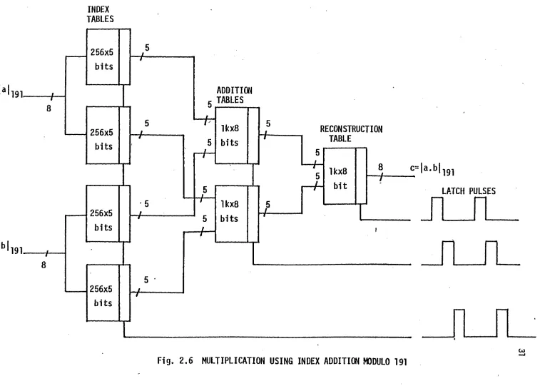
Fig. (2 .6 ) shows the block diagram fo r m u ltip lic a tio n modulo
191 using sub-moduli 30 and 31. Note the s im ila r ity between Fig. (2 .4 )
to perform addition and Fig. (2 .6 ) to perform m u ltip lic a tio n . Both
operations now take the same tim e, number o f stages and same number
o f ROMS.
2 .5 SUMMARY
In th.is chapter the basic idea o f modular arith m etic was presented.
The residue number system was described and was applied to perform
binary operations namely a d d itio n , su b traction , m u ltip lic a tio n and
d iv is io n . The method was c le a rly illu s tr a te d by using examples. The
a d o p tib ility o f the RNS fo r a look up ta b le implementation o f
m u ltip lic a tio n and addition was shown.
From the discussion in th is chapter i t can now be concluded th a t
the RNS is an e f f ic ie n t and fa s t way o f performing a d d itio n , subtraction
and m u ltip lic a tio n since i t is in h eren tly a carry borrow fre e system and
there is no in t e r d ig it dependence. D ivision is possible only in c e rta in
cases.
The RNS also o ffe rs the best re s u lt fo r hardward implementation
using look up ta b le s . M u ltip lic a tio n modulo a prime number can be
e f f ic ie n t ly implemented and o ffe rs the same speed o f operation as
a d d itio n .
Re pr od uc ed w ith pe rm is si o n of th e co py ri gh t o w ne r. Fu rthe r rep roduction p ro h ib it e d wi th ou t p e rm is s io n . INDEX TABLES Ib| ADDITION TABLES 191 RECONSTRUCTION TABLE
c= | a. b | ig-j
LATCH PULSES
3.1 INTRODUCTION TO DIGITAL CONVOLUTION
F in ite d ig ita l convolution has many powerful applications in
d ig ita l signal processing. I t is used to implement non-recursive
or f i n i t e impulse response d ig ita l f i l t e r s . I t is also used to carry
out auto and cross co rrelatio n as well as fo r computation such as
polynomial m u ltip lic a tio n [43.
3.1.1 F in ite Linear Convolution
F in ite lin e a r discrete convolution o f two sequences is mathematically
represented as
n.,+n2-i
yCn) = £ h(n-m) x(m) n=0,l , 2, . . .(N-,+N9- l ) (3 .1 )
m=0 1 *
where x (n ), h(n) and y(n) are the f i n i t e d ig ita l sequences of length
N.j, N2 and N-j+Ng-l resp ectively. Fig. 3.1 shows a simple p ic to ria l
representation o f how lin e a r convolution is carried out in practice.
Fig. .3.1(a) shows a typ ica l sequence x (n ) th a t is non-zero in the range
0 < n < 4. Fig. 3 .1 (b ) shows the sequence h(n) th a t is non-zero fo r
0 <_ n _< 7. Fig. 3 .1 (c ) shows the m irror image o f h(n) along the y -a x is .
Fig. 3.1 (d ) to Cf) show simultaneous plots o f x(m) and h(n-m). fo r
n=T j4 ,1 1. C learly fo r n < 0 and n > 11, there is no overlap between
33
x(n)
; C * ¥
n n
Ca)
0
h(n)
i-L-L
(b)
Q
h (-fl)
i i I I I I
( 0
a
hO»fl)
« *; ft x *
M r 1 1 1 n
Cd)
hi 4-n)
, I 1
i- ft ji 1 1'
a ;I
n
-3 4
( a )
h (T l-n )
h » y ft ft
I I I
( f )
n)
n
(g)
n
shows y ( n ) , which is the desired convolution.
"3 .1 .2 Periodic or Cyclic Convolution
I f h(n) represents one period o f the periodic sequence hp(n ),
and xCn) represents th a t o f xp(n ), of both period N samples, then the
periodic or cy c lic convolution o f h(n) and x ( n ) is defined as
N-l
yCn) = I x(m) h |n - m |N fo r n = 0,1, . . ,N-1 (3 .2 )
m=0
and is represented as y (n ) = x(n) * h(.n). Because o f the
p e rio d ic ity , sequences x (n) and h (n-m) are considered
r r
only in the in te rv a l 0 _< m <_ N -l.
As the samples o f hp(n-m) s lid e past m =N -l, the id e n tica l samples
appear a t m=0. Thus the term c y clic convolution is a description o f
the convolution o f two sequences defined on a c ir c le . When two periodic
sequences are convolved, the output sequence is periodic and o f the same
period.
3 .1 .3 Linear Convolution Via Cyclic Convolution
Consider two f i n i t e duration sequences x(n) and h (n ). The duration
of x(n) is N-j and the duration o f h(n) is Ng. The lin e a r convolution of
x(n) and h(n) yie ld s the sequence y ( n ) of duration N^+Ng-l. To obtain
th is sequence using c y c lic convolution, both input sequences should also
be o f period N -j+ ^ -l. Zeros can be appended to these input sequences
to make them o f duration N^+Ng-l and then c irc u la r convolution can be
35
3.2 DISCRETE FOURIER TRANSFORM
F in ite d ig ita l convolution can be implemented using transforms
having the cyclic convolution property (ccp). The ch aracteristics of
these transforms are such th at the transform of convolution in the time
domain is equal to the term by term product in the transform domain.
One o f the transforms th at e x h ib it ccp is the Discrete Fourier
Transform (DFT) and is given by
N-l nl>
DFT X(k) = I x(n) W , k = 0,1
n=0
where W = exp ( - 0 j|p).
N-l (3 .3 )
The inverse transform (_IDFT) is given by
(3 .4 )
Then the cy c lic convolution property is given as
I f yCn) - x(n) ( * ) h(n)
(3 .5 )
then Y(k) = X(k) . H(k)
where X, H and Y are the respective transforms of x , h and y.
To prove the ccp o f DFT, take
N-l
(3 .6 )
Take the transform o f both sides o f equation (3 .6 )
YDCk) = I I I x CD hCn-D } e
p n=0 1=0 p
N -l N-l
IN-1 N - l
I
-xD0 1 iI
h (n -U • e 1=0 p n=0_______ __,
2
* C n -l)-kN } e
J
KpCk)
XpCk)
or
YpCk} = XpCk) • HpCk). which is the desired re s u lt.
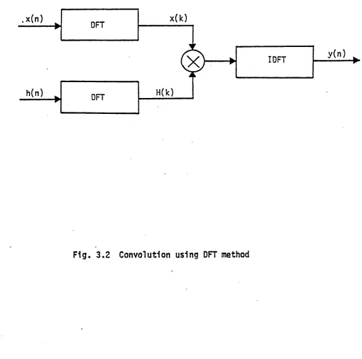
Using the ccp o f DFT, convolution can be implemented in the
follow ing way
i ) take the DFT o f both the input sequences
i i ) obtain the term by term product in transform domain
i i i l perform the inverse DFT to obtain the output sequence.
The block diagram o f Fig. 3.2 shows the complete procedure to
perform convolution.
3.3 FAST FOURIER TRANSFORM (FFT)
The term FFT re fe rs -to a number o f algorithms th at employ a
number o f methods fo r reducing the computation time required to
compute a DFT. They make use o f the symmetry and p e rio d ic ity of
de-x(k) . x (n )
H(k) h(n)
DFT
IDFT
DFT
compose a long DFT computation into smaller length DFT computations.
To compute an N point DFT, a to ta l o f (N -l) complex m u ltip lic a tio n s
and N (N -l) additions are required while using the FFT fo r the same N
transform requires approximately loggN m u ltip lic a tio n and N log2N
addition fo r radix 2 algorithm . B asically there are two types of
FFT algorithm s, called'decim ation in time (D IT) and decimation in
frequency (D IF ).
3.3.1 Decimation in Time Algorithm (DIT)
The algorithm in which the input sequence (time domain) is
decomposed in to smaller sequences is called a DIT algorithm. The
procedure is illu s tr a te d fo r an N point sequence where N = 2r ,
r is an in te g e r.
By d e fin itio n :
N- 1 _ u
X(k) = I x(n) W k = 0 , 1 , 2 , . . , N-l
n=0
Define two point sequences x-j(n) and x2(n) as the even and odd
members of x (n ).
x-j (n ) = x (2n) '
n = 0,1,2, . . , | - 1
39
Then N-point DFT is
Xtk) = I x (2 n l W?n k + I aC2n+l) WNC2n+1)k
n=0 n n= 0 N
. 2ir 0 . 2u/N/2
? M * “J
where WN = e = e = WN /2
N , n ,
2 2
XCk) = J x-jCn) Wjk 2 + wj^ I x2(n) wj] k 2
= X-j (k) + Wk X2Ck)
where X-jCk) and X2Ck) are point DFT's, and of period ^ . Therefore,
XCk) = X1 Ck) + Wk X2Ck) 0 < k < | - 1
= X1 Ck-J-) + wj X2C k 4 ) | < k £ N-l .
2
As mentioned, fo r d ire c t evaluation of an N point DFT, N m u ltip lic atio n s
N
are required. S im ila rly , d ire c t eva-luation of an ^ point DFT, requires
t?r} 2 m u ltip lic a tio n s . I f the above procedure is used to compute an N point
DFT, a to ta l of
m 2
C^-) • 2 + N m u ltip lic a tio n s are required and
i.2 ^ 2
fo r F » N approximately g- m u ltip lic a tio n are required and