Electronic Theses and Dissertations Theses, Dissertations, and Major Papers
1-1-2019
Synthesis, Characterization, and Reactivity of Chelating Ligand
Synthesis, Characterization, and Reactivity of Chelating Ligand
Complexes of Group 13-15 Elements
Complexes of Group 13-15 Elements
Ala'aeddeen Swidan University of Windsor
Follow this and additional works at: https://scholar.uwindsor.ca/etd Part of the Chemistry Commons
Recommended Citation Recommended Citation
Swidan, Ala'aeddeen, "Synthesis, Characterization, and Reactivity of Chelating Ligand Complexes of Group 13-15 Elements" (2019). Electronic Theses and Dissertations. 7761.
https://scholar.uwindsor.ca/etd/7761
Synthesis, Characterization, and Reactivity of Chelating Ligand Complexes of Group 13-15 Elements
By
Ala’aeddeen Swidan
A Dissertation
Submitted to the Faculty of Graduate Studies through the Department of Chemistry and Biochemistry
in Partial Fulfillment of the Requirements for the Degree of Doctor of Philosophy
at the University of Windsor
Windsor, Ontario, Canada
2019
Synthesis, Characterization, and Reactivity of Chelating Ligand Complexes of Group 13-15 Elements
by
Ala’aeddeen Swidan
APPROVED BY:
______________________________________________ D. Richeson, External Examiner
University of Ottawa
______________________________________________ J. Gagnon
Earth and Environmental Sciences
______________________________________________ J.R. Green
Department of Chemistry and Biochemistry
______________________________________________ S. Johnson
Department of Chemistry and Biochemistry
______________________________________________ C. Macdonald, Advisor
Department of Chemistry and Biochemistry
PUBLICATION
Co-Authorship
I hereby declare that this dissertation incorporates material thatis a result of joint research, as follows:
Chapter 2 of the dissertation contains results published in the original research communication “2,6-Bis(benzimidazol-2-yl)pyridines as more electron-rich and sterically accessible alternatives to 2,6-bis(imino)pyridine for group 13 coordination chemistry” (Swidan, A.; Binder, J. F.; St. Onge, P. B.; Suter, R.; Burford, N.; Macdonald, C. Dalton Trans. 2019, 1284–1291). Mr. St. Onge contributed to the synthesis and characterization of some of the reported compounds, Mr. Binder contributed to the computational studies, Dr. Macdonald and Dr. Suter helped in the writing and editing of the manuscript.
Chapter 3 of the dissertation contains results published in the original research article “2,6-Bis(benzimidazol-2-yl)pyridine Complexes of Group 14 Elements” (Swidan, A.; St. Onge, P. B.; Binder, J. F.; Suter, R.; Burford, N.; Macdonald, C. Dalton Trans.2019, 48, 7835-7843). Mr. St. Onge contributed to the synthesis and characterization of some the reported compounds, Mr. Binder contributed to the computational studies, Dr. Macdonald helped in the writing, editing and provided ideas to investigate and include in the manuscript.
I am aware of the University of Windsor Senate Policy on Authorship and I certify that I have properly acknowledged the contribution of other researchers to my dissertation and have obtained written permission from each of the co-author(s) to include the above material(s) in my dissertation. I certify that, with the above qualification, this dissertation, and the research to which it refers, is the product of my own work.
Previous Publication
This dissertation includes 3 original papers that have been previously published/submitted for publication in peer-reviewed journals, as follows:
Dissertation
Chapter Publication title/full citation Publication status
Chapter 2 “2,6-Bis(benzimidazol-2-yl)pyridines as more electron-rich and sterically accessible alternatives to 2,6-bis(imino)pyridine for group 13 coordination chemistry” Swidan, A.; Binder, J. F.; St. Onge, P. B.; Suter, R.; Burford, N.; Macdonald, C. Dalton Trans.
2019, 1284–1291.
Published
Chapter 3 “2,6-Bis(benzimidazol-2-yl)pyridine Complexes of Group 14 Elements” Swidan, A.; St. Onge, P. B.; Binder, J. F.; Suter, R.; Burford, N.; Macdonald, C. Dalton Trans.2019, 48, 7835-7843.
Published
Chapter 5 “Tris(benzoimidazol)amine (L) complexes of pnictogen(III) and pnictogen(V) cations and assessment of the [LP]3+/[LPF2]3+ redox couple” Swidan, A.; Suter, R.; Macdonald, C. L. B.; Burford, N. 2018, 5837–5841.
Published
I certify that I have obtained written permission from the copyright owner(s) to include the above published material(s) in my dissertation. I certify that the above material describes work completed during my registration as a graduate student at the University of Windsor.
General
in my dissertation, published or otherwise, are fully acknowledged in accordance with the standard referencing practices. Furthermore, to the extent that I have included copyrighted material that surpasses the bounds of fair dealing within the meaning of the Canada Copyright Act, I certify that I have obtained written permission from the copyright owner(s) to include such material(s) in my dissertation.
2,6-bis(benzimidazol-2-yl)pyridine derivative (G-BZIMPY, G = NBn,
N(3,5-CF3)Bn, N-allyl and O) have been used as pincer ligands to coordinate and isolate
various group 13-15 complexes. For Group 13, treatment of G-BZIMPY with two
equivalents of GaCl3 results in the self-ionization products [G-BZIMPYGaCl2][GaCl4].
This Ga(III) complex can be reduced to a Ga(I) centre using K2[Fe(CO)4] as a reducing
agent to result in the Ga(I) complex [(NBn-BZIMPY)(Cl)Ga–Fe(CO)4] (Chapter 2).
Group 14 complexes of G-BZIMPY have been synthesized in a similar fashion
through the self-ionization reactions of G-BZIMPY with two equivalents of MCl2 (M =
Ge, Sn) to yield [G-BZIMPYMCl][MCl3]. Attempts to reduce these complexes into the
M(0) centre were not successful. Other reactivities and UV-vis studies are detailed in
this dissertation (Chapter 3). Comparison of group 13 and 14 complexes of G-BZIMPY
to complexes of the structurally similar bis(imino)pyridine (DIMPY) are studied and
reveal G-BZIMPY as a stronger donor than DIMPY for group 13 coordination. For
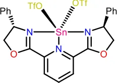
group 15 elements, treatment of PnCl3 (Pn = P, As, Sb) with G-BZIMPY does not yield
any reactivity, however, the addition of TMS-OTf (Trimethylsilyl
trifluoromethanesulfonate) results in the isolation of [G-BZIMPYPnCl][OTf]2 (Chapter
4).
In-addition, a tetradentate ligand
tris((1-ethyl-benzoimidazol-2-yl)methyl)amine (BIMEt3) has been investigated. A series of cationic complexes
involving a pnictogen(III) (Pn = P, As, Sb) centre coordinated to BIMEt3 have been
XeF2 provides access to [PF2(BIMEt3)]3+ representing the first structurally
characterized example of a phosphorus(V) centred trication (Chapter 5).
Attempts to synthesize an anionic carbon(0) are detailed in chapter 6.
Although obtaining an anionic carbon(0) was not successful, it lead to a series of
interesting compounds and results. Compounds containing carbon centre behave
differently than their heavier group-14 analogues of the same bidentate anionic
My academic journey would not have been possible if it wasn’t for the support
of my community. My community has provided me with the necessary environment
and tools to be successful and for that, I am eternally gratefully and will always be
indebted to this loving and caring community.
My supervisor, Dr. Charles L. B. Macdonald, has been very supportive
throughout the years and I am very thankful to have him as my mentor and for giving
me the opportunity to join his research group. Despite his busy schedule, Chuck is
always available, even after moving to Carleton, Chuck is available to answer
questions and would free-up time to be there for the group. Working with Chuck
allowed me opportunities that helped me improve by building on my experiences and
skills. Different collaborations and taking part in developing a course are among the
many opportunities that were made available to me by Chuck, and for that, I am very
thankful.
The Macdonald group members have made this journey an enjoyable one and
for that, I would like to thank all the past and present group members. Special thanks
to Blake whom I mentored in his 410 project and by having him on-board, he helped
make significant advances. Although I was mentoring and training Blake, I myself
have learned a lot from Blake. I would like to thank Justin for the continued
collaborations we had over the years and for all the good times spent together in and
out of the lab. When it comes to chemistry discussions between Justin and myself, if
numerous conversations and hangouts we had. Lastly, I would like to thank Steph,
Max and Loue for making the lab a fun place to be in and for the amazing memories
that I will cherish forever.
I would like to thank our collaborators, Dr. Neil Burford and Dr. Riccardo Suter
for the amazing collaborations we had over the last two years. Meeting Dr. Suter at
the Toronto CSC conference in 2017, little did I know the extent this collaboration will
have, and I am very pleased in the turnout of this fruitful collaboration between the
two groups.
In the chemistry department, I would like to thank Dr. Matthew Revington for
his help and training in the NMR instruments. Dr. Janeen Auld for her help in the
set-up of elemental analysis instruments, making it always available and ready to go. A
special thanks to Marlene Bezaire, our graduate secretary, for keeping me on track to
graduate and for all the love and support she shows to graduate students. She is very
caring and wants all students to be successful, she tries her best to make this happen.
In addition, I would like to thank our undergraduate laboratory coordinators, Una Lee
and Nedhal Al-Nidawy, for the opportunity to teach and mentor undergraduate
students over the years.
I would like to thank my committee members, not only for agreeing to be on
my committee but also for providing guidance and assistance throughout my degree.
Dr. Green is always my go to when I have any questions or problems with synthesis
clarify. Working with Dr. Johnson on the inorganic chemistry tutorials is something I
really enjoyed, and I looked forward to GAing the course year after year. I would like
to thank Dr. Maeva for agreeing to be my outside-of-department reader at the
beginning of my PhD. I would like to thank Dr. Joel Gagnon for agreeing to fill-in for
Dr. Maeva and really appreciate his time and willingness to be on my committee. I
would like to thank Dr. Richeson for agreeing to be my external examiner and really
appreciate his time and the trouble of travel. Dr. Richeson’s research has been of great
interest to me and some of the research results in this dissertation were a direct
inspiration of work reported by Dr. Richeson. Additionally, I would like to thank Dr.
Peter T. Wolczanski for being a great mentor during time at Cornell University as a
graduate student. Pete is very supportive, and I have learned a lot in the short span of
time I spent with Pete.
Last but not least, I would like to thank my wife who has been supportive and
understanding. Having to leave in the middle of the night to mount the next crystal
when it’s our turn on the diffractometer is something I had to do frequently, and my
wife has been very supportive throughout my PhD journey and I would like to thank
DECLARATION OF CO-AUTHORSHIP AND PREVIOUS PUBLICATION ... III ABSTRACT ... VI DEDICATION ... VIII ACKNOWLEDGEMENTS... IX LIST OF TABLES ... XVI LIST OF FIGURES ... XVIII LIST OF SCHEMES ...XXIV LIST OF ABBREVIATIONS, SYMBOLS, AND UNITS ... XXVII
CHAPTER 1: Introduction ... 1
1.1 General Introduction ... 1
1.2 Oxidation States ... 3
1.3 Chemical Bonding: The Covalent Bond ... 6
1.4 Pincer Ligands ... 9
1.5 Pincer Complexes of Group 15 Elements and Their Role in Modern Main Group Chemistry ...14
1.6 Pincer Complexes of Group 14 Elements and Their Role in Modern Main Group Chemistry ...20
1.7 Pincer Complexes of Group 13 Elements and Their Role in Modern Main Group Chemistry ...23
1.8 References ...30
CHAPTER 2: 2,6-Bis(benzimidazol-2-yl)pyridine as More Electron-Rich and Sterically Accessible Alternatives to 2,6-bis(imino)pyridine for Group 13 Coordination Chemistry ... 36
2.1 Introduction ...36
2.2 Results and Discussion ...39
2.2.3 Computational Studies ...48
2.3 Conclusions ...49
2.4 Experimental ...50
2.4.1 General Remarks ...50
2.4.2 Synthesis ...51
2.4.3 Computational Details ...57
2.4.4 X-ray Crystallography ...58
2.5 References ...63
CHAPTER 3: 2,6-Bis(benzimidazol-2-yl)pyridine Complexes of Group 14 Elements ... 69
3.1 Introduction ...69
3.2 Results and Discussion ...72
3.2.1 Synthesis and Characterization ...72
3.2.2 UV-vis Studies ...79
3.2.3 Reduction Attempts ...82
3.2.4 Computational Studies ...85
3.3 Conclusions ...86
3.4 Experimental ...87
3.4.1 General Remarks ...87
3.4.2 Synthesis ...88
3.4.3 Computational Details ...95
3.4.4 X-ray Crystallography ...95
3.5 References ... 101
CHAPTER 4: 2,6-Bis(benzimidazol-2-yl)pyridine Complexes of Group 15 Elements ... 107
4.2 Results and Discussion ... 109
4.2.1 Synthesis and Characterization ... 109
4.3 Conclusions ... 114
4.4 Experimental ... 115
4.4.1 General Remarks ... 115
4.4.2 Synthetic Information ... 116
4.4.3 X-ray Crystallography ... 118
4.5 References ... 121
CHAPTER 5: Tris(benzoimidazol)amine (L) complexes of pnictogen(III) and pnictogen(V) cations and the [LP]3+/[LPF2]3+ redox couple ... 127
5.1 Introduction ... 127
5.2 Results and Discussion ... 128
5.3 Conclusions ... 137
5.4 Experimental ... 137
5.4.1 General Remarks ... 137
5.4.2 Synthesis ... 138
5.4.3 X-ray Crystallography ... 145
5.5 References ... 149
CHAPTER 6: Towards the Synthesis of an Anionic Carbon(0) ... 153
6.1 Introduction ... 153
6.2 Results and Discussion ... 159
6.2.1 Attempted Synthesis of an Anionic Carbodiphosphorane ... 159
6.2.2 Attempted Synthesis of an Anionic Carbodicarbene ... 166
6.3 Conclusions ... 171
6.4.2 Synthesis ... 172
6.4.3 X-ray Crystallography ... 175
6.5 References ... 178
CHAPTER 7: Conclusions and Future Work ... 182
7.1 Dissertation Overview ... 182
7.2 Bidentate Ligands ... 182
7.2.1 Bidentate Ligands Toward the synthesis of an Anionic Carbon(0) ... 182
7.2.2 Bidentate Ligands for Group 13 and 14 Coordination – Part 1 ... 184
7.2.3 Bidentate Ligands for Group 13 and 14 Coordination – Part 2 ... 188
7.3 Neutral Pincer (Tridentate) Ligand Donor for Groups 13-15 ... 191
7.4 Trianionic Pincer (Tridentate) Ligand Donor for Phosphorus ... 192
7.5 Conclusions ... 196
7.6 Experimental ... 197
7.6.1 General Remarks ... 197
7.6.2 Synthesis ... 198
7.6.3 X-ray Crystallography ... 200
7.7 References ... 203
Table 2.1. Selected bond distances (Å) and angles (°) of complexes 1-7. ... 43
Table 2.2. Selected bond distances (Å) of [NBn-BZIMPYGaCl2][GaCl4] (1), [(NBn-BZIMPY)(Cl)Ga—Fe(CO)4] (7), [iPrPDIAlCl2][AlCl4] (6) and Berben’s [iPrPDIAlCl]. ... 46
Table 2.3. IR absorptions in the νCO range of complex 7, Fischer’s tmeda based complexes35 and Robinson’s multi-bonded Fe-Ga complex38 and Jutzi’s Cp*Ga -Fe(CO)4 complex39. L = tmeda, L’ = 2,6-bis(2,4,6-triisopropylphenyl)-phenyl, L’’ = Cp* and L’’’ = NBn-BZIMPY. ... 47
Table 2.4. Crystallographic data and structure refinement. ... 60
Table 2.5. Crystallographic data and structure refinement. ... 61
Table 2.6. Crystallographic data and structure refinement. ... 62
Table 3.1. Selected bond distances (Å) and angles (°) of complexes 1-6, and [iPrDIMPYMCl]+ (M = Ge, Sn)12. ... 74
Table 3.2. Selected bond distances (Å) and angles (°) of complexes 7-10. ... 79
Table 3.3. Crystallographic data and structure refinement. ... 97
Table 3.4. Crystallographic data and structure refinement. ... 98
Table 3.5. Crystallographic data and structure refinement. ... 99
Table 3.6. Crystallographic data and structure refinement. ... 100
Table 4.1. Selected bond distances (Å) and angles (°) of complexes 1, 2 and 3. ... 113
Table 4.2. Crystallographic data and structure refinement. ... 120
Table 5.1. Summary of Gibbs free energies for optimized gas phase structures for the stepwise methylation of [P(BIM)] at the PBEPBE/6-311+G(d,p) level of theory. N-methylation in blue and P-methylation in red. ... 130
Table 5.2. Selected bond distancesin Å, angles in ° and 31P NMR chemical shiftsin ppm for P(BIM), [P(BIMEt3)][OTf]3 and [PF2(BIMEt3)][OTf]3 ... 136
Table 5.5. Crystallographic data and structure refinement. ... 147 Table 5.6. Crystallographic data and structure refinement. ... 148 Table 6.1. νCO stretching frequencies cis-[RhCl(CO)2(L)] complexes where L = PR3,
NHC and CDC. ... 157 Table 6.2. Selected bond distances (Å) and angles (°) of compounds 1 and 2 along with
Ragogna’s [Ph2B(CH2PPh2)2MCl] (M = Ge, Sn). ... 165 Table 6.3. Selected bond distances (Å) and angles (°) of compounds VI and 6-8. .... 168 Table 6.4. Crystallographic data and structure refinement. ... 176 Table 6.5. Crystallographic data and structure refinement. ... 177 Table 7.1. Selected bond distances (Å) and angles (°) of compounds 2, 3, and 4 along
with Ragogna’s [Ph2B(CH2PPh2)2MCl] (M = Ge, Sn)... 186 Table 7.2. Selected bond distances (Å) and angles (°) of 5 and (NRBz)2CHBPh2 (from
Figure 1.1. Oxidation states of phosphorus in different molecules showing how
oxidation state is not always consistent with valence state. ... 4
Figure 1.2. A more convenient model to assigning an oxidation state based on the number of lone pairs present on a given atom. ... 5
Figure 1.3. Different Lewis drawings of carbodiphosphorane showing how the assignment of oxidation state on the carbon centre can be different depending on the way the Lewis structure is drawn. ... 6
Figure 1.4. A Lewis structure of a dioxygen atom (O2). ... 7
Figure 1.5. Molecular orbital diagram of dihydrogen. ... 8
Figure 1.6. Molecular orbital diagram of an O2. ... 9
Figure 1.7. Arduengo’s 10–As–3 T–shaped complex (mer-, left) and in the bent shape (fac-, right). ... 10
Figure 1.8. Classification of pincer ligands based on the overall charge of the pincer ligand, neutral (L3), anionic (XL2), dianionic (X2L) or trianionic (X3). ... 11
Figure 1.9. Goldman and Brookhart’s Iridium(III) catalyst (left) and Moulton’s Nickel(II) (right) are examples of robust metal pincer catalysts. ... 12
Figure 1.10. An example of how the tuning of pincer ligand can affect the reactivity of the catalyst. ... 12
Figure 1.11. Examples of chiral [N,N,N] pincer ligands. ... 13
Figure 1.12. An example of a redox non-innocent ligand that allows Ta(V) undergo reaction with nitrene without changing the preferred oxidation state of the metal centre. ... 14
Figure 1.13. Arduengo’s 10–P–3 T–shaped complex and its different resonance structures (left), and 8–P–3 bent complex (right). ... 15
Figure 1.16. Early examples of pincer-type complexes of group 14 main group elements. ... 20 Figure 1.17. Evans’ tin(II) chiral Lewis acid complex. ... 21 Figure 1.18. MO diagram depicting the difference between an L- and a Z-type ligand
coordinating to a transition metal. ... 25 Figure 1.19. Takaya and Iwasawa’s palladium(II) catalyst with E = Al, Ga and In. .... 26 Figure 2.1. DIMPY ligand, B: BZIMPY ligand (G = NH, NBn, N(3,5-CF3)Bn, N-Allyl and
O). ... 38 Figure 2.2. Solid state structure of the cations in [NBn-BZIMPYGaCl2][GaCl4] (1, left)
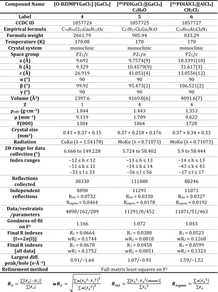
and [NAllyl-BZIMPYGaCl2][GaCl4] (3, right). Thermal ellipsoids are shown at 50% probability level. Hydrogen atoms, solvent molecules and counter anions are omitted for clarity. Selected bond distances and angles are given in Table 2.1. ... 40 Figure 2.3. Solid state structure of the cation in [O-BZIMPYGaCl2][GaCl4] (4). Thermal
ellipsoids are shown at 50% probability level. Hydrogen atoms, solvent molecules and counter anion are omitted for clarity. Selected bond distances and angles are given in Table 2.1. ... 41 Figure 2.4. Solid state structure of the cations in [iPrDIMPYGaCl2][GaCl4] (5, left) and
[iPrDIMPYAlCl2][AlCl4] (6, right). Thermal ellipsoids are shown at 50% probability level. Hydrogen atoms, solvent molecules and counter anions are omitted for clarity. Selected bond distances and angles are given in Table 2.1. 42 Figure 2.5. Solid state structure of [(NBn-BZIMPY)(Cl)Ga—Fe(CO)4] (7). Thermal
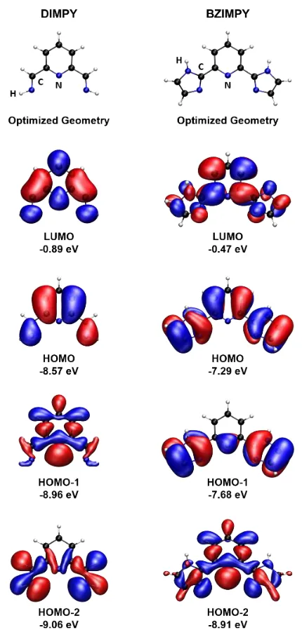
ellipsoids are shown at 50% probability level. Hydrogen atoms and solvent molecules are omitted for clarity. Selected bond distances (Å) of 7: Ga-Fe 2.3861(7), Ga-Cl 2.2477(10), axC-O 1.148(5), eqC-O 1.160(4), 1.152(5), 1.162(5). Selected bond distances (Å) of Driess’ complex: Ga-Fe 2.4010(12), Ga-Cl 2.2463(6), axC-O 1.149(3), eqC-O 1.168(3), 1.157(2), 1.156(3). Other selected bond distances and angles of 7 are given in Table 2.2. ... 47 Figure 2.6. Optimized geometries and selected molecular orbitals of simplified
Figure 3.2. Solid state structure of the cations in [NBn-BZIMPYGeCl][GeCl3] (1, left) and [NBn-BZIMPYSnCl][SnCl3] (2, right). Thermal ellipsoids are shown at 50% probability level. Hydrogen atoms, solvent molecules and counterions are omitted for clarity. Selected bond distances and angles are listed in Table 3.1. 72 Figure 3.3. Solid state structure of the cations in [Allyl-BZIMPYGeCl][GeCl3] (5, left)
and [O-BZIMPYGeCl][GeCl3] (6, right). Thermal ellipsoids are shown at 50% probability level. Hydrogen atoms, solvent molecules and counterion are omitted for clarity. ... 75 Figure 3.4. Solid state structure of the cations in [NBn-BZIMPYGeCl][OTf] (7, left) and
[NBn-BZIMPYSn][OTf]2 (8, right). Thermal ellipsoids are shown at 50% probability level. Hydrogen atoms and solvent molecules are omitted for clarity. Selected bond distances and angles are listed in Table 3.2. ... 77 Figure 3.5. a) UV-vis absoption of 1 in DCM vs CH3CN along with 7 in DCM. b) UV-vis
absoption of 2 in DCM vs CH3CN along with 8 in DCM. c) UV-vis absoption of 6 in DCM vs CH3CN. d) UV-vis absoption of 3-5 in DCM. Spectra collected in CH3CN are indicated by the dashed line... 82 Figure 3.6. Solid state structure of the cations in [(NBn-BZIMPY)2Ni][GeCl3]2 (9, left)
and [(NBn-BZIMPY)2Ni][SnCl3]2 (10, right). Thermal ellipsoids are shown at 50% probability level. Hydrogen atoms and solvent molecules are omitted for clarity. Selected bond distances and angles are listed in Table 3.2. ... 83 Figure 3.7. Overlapping CVs of 0.01M solution of ferrocene (Fc/Fc+) in black and
0.01M solution of ferrocene/NBn-BZIMPY in red. Both solutions were prepared in DCM with 0.1M [NBu4][PF6]. Working and counter electrodes were Pt, the reference electrode was Ag/AgCl, and the scan rate was 100 mVs–1. ... 84 Figure 3.8. Optimized geometry and selected occupied molecular orbitals of 1’ (M062X/cc-pVTZ). ... 86 Figure 4.1. Arduengo’s 10–P–3 (T-shaped) and 8–P–3 (bent) phosphines. ... 108 Figure 4.2. A: DIMPY ligand, B: BZIMPY ligand (G = NH, NBn, N(3,5-CF3)Bn, N-Allyl
[NBn-ellipsoids are shown at 50% probability level. Hydrogen atoms and solvent molecules are omitted for clarity. Selected bond distances and angles of complexes 1-3 are in Table 4.1. ... 111 Figure 4.4. 1H NMR of 1 (red), 2 (green), 3 (blue), and free NBn-BZIMPY ligand (black). ... 114 Figure 5.1. Highlight of the phosphorus containing compounds synthesized (left),
BIMH3 ligand (right)... 128 Figure 5.2. (a) Solid state structure of one of two independent molecules of P(BIM).
(b) Solid state structure of the cation in [P(BIMEt3)][OTf]3•(MeCN)2. (c) Solid state structure of the cation in [PF2(BIMEt3)][OTf]3•MeCN. Thermal ellipsoids are shown at a 50% probability level. Hydrogen atoms, solvent molecules and triflate anions are omitted for clarity. Inter-atomic distances and angles are summarized in Table 5.2. ... 131 Figure 5.3. Solid state structure of (a) [AsCl(BIMEt3)]2+, (b) [SbF(BIMEt3)]2+ , (c)
[As(BIMEt3)]3+ and (d) [Sb(BIMEt3)]3+. Thermal ellipsoids are shown at a 50% probability level. Oxygen atoms of the triflate anions that interact with the pnictogen centres are shown, but the other atoms of the anions are omitted for clarity as well as the hydrogen atoms and solvent molecules. Interatomic distances and angles are summarized in Table 5.3. ... 133 Figure 5.4. NMR spectra for [PF2(BIMEt3)][OTf]3 in CD3CN. ... 135 Figure 6.1. Grubbs’ second-generation catalyst (top), and some notable examples of
the use of N-heterocyclic carbenes in the stabilization of low-valent group 13-15 elements. ... 154 Figure 6.2. Depiction of carbon centres in the +4 (left), +2 (centre) and 0 (right)
oxidation states. ... 154 Figure 6.3. Frontier orbital difference between a carbon(+2) (left) and a carbon(0)
(right). The carbon(+2) shown is assuming a singlet state. ... 155 Figure 6.4. An example of carbon(0) with a σ and a π-donor (left), with two σ-donor
orbitals (right). ... 156 Figure 6.5. Selected examples of carbodiphosphorane complexes of transition metals
Figure 6.6. Solid state structure of 1 (left). Thermal ellipsoids are shown at 50% probability level. Hydrogen atoms and solvent molecules are omitted for clarity. Selected bond distances and angles are given in Table 6.2. 31P{1H} NMR of 1 (right). ... 162 Figure 6.7. Solid state structure of 2. Thermal ellipsoids are shown at 50% probability
level. Hydrogen atoms and solvent molecules are omitted for clarity. Selected bond distances and angles are given in Table 6.2. ... 164 Figure 6.8. Solid state structure of Ragogna’s [Ph2B(CH2PPh2)2GeCl] (left) and
Ragogna’s [Ph2B(CH2PPh2)2SnCl] (right). Thermal ellipsoids are shown at 50% probability level. Hydrogen atoms and solvent molecules are omitted for clarity. Selected bond distances and angles are given in Table 6.2. ... 165 Figure 6.9. Solid state structure of 6 (left) and 7 (right). Thermal ellipsoids are shown
at 50% probability level. Hydrogen atoms and solvent molecules are omitted for clarity. Selected bond distances and angles are given in Table 6.3. ... 168 Figure 6.10. Core structure of BODIPY (left) and a suspension of compound 6 in dark
(middle) and under UV-light (right). ... 169 Figure 6.11. A series of ruthenium-based catalysts reported by Grubbs. ... 171 Figure 7.1. Solid state structure of tBuCp(PPh2)2GeCl (2, left) and tBuCp(PPh2)2SnCl
(3, right). Thermal ellipsoids are shown at 50% probability level. Hydrogen atoms and solvent molecules are omitted for clarity. Selected bond distances and angles are listed in Table 7.1. ... 185 Figure 7.2. Solid state structure of (GeCl2)PPh2Cp(PPh2)2GeCl (4). Thermal ellipsoids
are shown at 50% probability level. Hydrogen atoms and solvent molecules are omitted for clarity. ... 186 Figure 7.3. Grown structure of 3 showing the intermolecular interaction present
between the GeCl fragment and the neighbouring GeCl2 fragment. ... 188 Figure 7.4. NacNac ligand (left) and [(GBz)2CH]- (right). ... 189 Figure 7.5. Left: Packing of 5 showing the intermolecular interactions present in the
Figure 7.6. Evans tin(II) chiral Lewis acid catalyst. ... 191 Figure 7.7. Structure of BZIMPY (left) and BZIM (right). ... 193 Figure 7.8. Solid state structure of the H-BZIMP(Et2N) (6). Thermal ellipsoids are
LIST OF SCHEMES
Scheme 1.1. The Reaction of ADSbO with hexafluoro-2-butyne (right) and with hexafluorobiacetyl (left). The reaction of bis(trifluoromethyl)dithiete with ADAsO (bottom). ... 16 Scheme 1.2. Radosevich’s synthesis of P(V)–H2 complex. ... 18 Scheme 1.3. Proposed mechanism of transfer hydrogenation catalysis of ADPO
catalyst. ... 19 Scheme 1.4. Examples of Group 15 low valent pincer complexes. ... 20 Scheme 1.5. Roesky’s DIMPY-M(II) complex (M = Ge, Sn) and Nikonov’s reduced Ge(0)
complex. ... 22 Scheme 1.6. Mechanism of the transamination reaction of DIMPY ligand with
Sn[N(SiMe3)2]2 to yield a Sn(0) complex. ... 22 Scheme 1.7. Zaitsev’s tridentate complexes and reactivity. ... 23 Scheme 1.8. Zwitterionic complexes containing ambiphilic pincer ligands. ... 24 Scheme 1.9. Reaction of DIMPY ligand with GaI, 2GaI3 or 2AlCl3. ... 27 Scheme 1.10. Reaction of DIMPY ligand with InOTf (left) and two equivalents of InCl3 (right). ... 27 Scheme 1.11. Reaction of DIMPY–FeCl2 with AlMe3 and AlEt3. ... 28 Scheme 1.12. Reaction of DIMPY with AlCl3 and AlCl2H. ... 29 Scheme 2.1. DIMPY complexes of group 13 elements. ... 36 Scheme 2.2. The synthesis of square planar Al(III) complexes. ... 37 Scheme 2.3. Reaction of [iPrDIMPYFeCl2] with AlMe3 and AlEt3. ... 38 Scheme 2.4. Self-ionization reactions of GaCl3 with G-BZIMPY ligands. ... 41 Scheme 2.5. Reaction of [NBn-BZIMPYGaCl2][GaCl4] with K2[Fe(CO)4] in THF to yield
[(NBn-BZIMPY)(Cl)Ga—Fe(CO)4] (7). ... 44 Scheme 3.1. Top: DIMPY (A) vs G-BZIMPY (G = NH, NBn, N(3,5-CF3)Bn, NAllyl and O).
Scheme 3.4. Self-ionization reactions of MCl3 (M = Ge, Sn) with G-BZIMPY ligands.. 73 Scheme 3.5. Reduction attempt of complexes 1 and 2 using Ni(COD)2 to yield
complexes 9 and 10 respectively (R = Bz). ... 84 Scheme 4.1. Low valent P(I) and As(I) complexes of DIMPY. Dipp = 2,6-diisopropylphenyl. ... 107 Scheme 4.2. Stephan’s dicationic P(III) catalyst. ... 108 Scheme 4.3. Reaction of MCl3 (M = P, As, Sb) with Bn-BZIMPY to yield complexes 1, 2
and 3. ... 110 Scheme 6.1. Synthesis of the first stable N-heterocyclic carbene. ... 153 Scheme 6.2. Bertrand’s synthesis of the first carbodicarbene. ... 157 Scheme 6.3. JCP-Tl ligand reactivity with heavier group 14 elements (Ge and Sn). 158 Scheme 6.4. Synthesis of Peters’ ligand, JCP-Li. ... 159 Scheme 6.5. Proposed synthesis of an anionic carbodicarbene using JCP-Li as the
starting ligand. ... 160 Scheme 6.6. Synthetic route to isolate neutral compound 1. Base = NaNH2 ... 161 Scheme 6.7. Synthetic route to isolate JCP-CBr (2) with and without the presence of
Zn0 powder. ... 163 Scheme 6.8. Reaction scheme showing the synthesis of triphosphenium P(I) cation
and the subsequent ligand exchange reaction with N-heterocyclic carbenes. 166 Scheme 6.9. Synthesis of compounds 3, 4, 6, and 7. G = NR, S or O, for VI, G = NMe. ... 167 Scheme 6.10. Reaction scheme showing synthesis of 8. ... 170 Scheme 7.1. Synthetic route for zwitterionic triphosphenium compound. ... 183 Scheme 7.2. A proposed reaction scheme to attain an anionic carbodiphosphorane. ... 184 Scheme 7.3. The proposed reaction of [Li][R-Cp(PPh2)2] with group 13 and 14 metal
halides... 184 Scheme 7.4. Proposed reaction of (GBz)2CH2 with group 14 metal halides (MX2, M =
Scheme 7.6. Proposed complex using R-PYBOX with PCl2X (X = Cl, Ph) and excess TMSOTf to yield R-PYBOX-PX. ... 192 Scheme 7.7. Synthesis of Verkade’s superbase. ... 193 Scheme 7.8. Proposed outcome of reacting BZIM with (Et2N)2PCl followed by KHMDS
LIST OF ABBREVIATIONS, SYMBOLS, AND UNITS
Å ångström
ADPnO 5-aza-2,8-dioxa-3,7-di-tert-butyl-1-[Pn]bicyclo[3.3.0]octa 3,6-diene *Pn = Pnictogen
AIM Atoms in Molecules
Anal. Analytical
Ar aryl
11B boron-11
BDE bond dissociation energy
Bn benzyl
Bn Benzyl (CH2-C6H5)
b broad
nBu n-butyl
tBu tert-butyl
BZIMPY 2,6-Bis(benzimidazol-2-yl)pyridine
13C carbon-13
C6D6 deuterated benzene
°C degree(s) Celsius
cal calorie(s)
calc. calculated
CDC carbodicarbene
CDP carbodiphosphorane
CHN carbon hydrogen nitrogen
cm–1 wavenumber(s)
cryst crystal
COD 1,5-cyclooctadiene
CSD Cambridge Structural Database
d doublet
deg (or °) degree(s)
DFT density functional theory
DIMPY bis(imino)pyridine
dppe bis(diphenylphosphino)ethane
Et ethyl
Et2O diethyl ether
eV electronvolt
19F fluorine-19
F structure factors (X-ray crystallography)
fac- facial
FT Fourier transform
g gram(s)
1H hydrogen-1
{1H} hydrogen-1 decoupled
HOMO highest occupied molecular orbital
HR-ESI-MS high-resolution electrospray ionization mass spectrometry
Hz hertz
IR infrared
J joule(s)
nJAB n-bond scalar coupling constant between nuclei A and B
K kelvin
kcal kilocalorie(s)
kJ kilojoule(s)
L liter
LCD Liquid-Crystal Display
LED Light-Emitting Diode
LUMO lowest unoccupied molecular orbital
m multiplet
Me methyl
Mes mesityl, 2,4,6-trimethylphenyl
MG main group
mg milligram
MHz megahertz
mL milliliter
mmol millimole
MO molecular orbital
mol mole
Mp melting point
mV millivolt
MW molecular weight
m/z mass/charge
NacNac 1,3-Diketimines derivatives
NBO natural bond orbital
NHC N-heterocyclic carbene
NMR nuclear magnetic resonance
NRT natural resonance theory
OAc acetoxy
ORTEP Oakridge Thermal Ellipsoid Plotting Program [OTf]− triflate, trifluoromethanesulfonate, [CF3SO3]−
p pentet
31P phosphorus-31
Ph phenyl
Pn pnictogen
ppm parts per million
iPr isopropyl
PYBOX bis(oxazoline)pyridine
q quartet
R hydrocarbyl
R reliability factor (X-ray crystallography)
Reflns reflections (X-ray crystallography)
s singlet
SCXRD single crystal X-ray diffraction
SIMes 1,3-bis(2,4,6-trimethylphenyl)-4,5-dihydroimidazol-2-ylidene SNHC S,N-heterocyclic carbene
t triplet
TD-DFT time-dependant density functional theory
tmeda tetramethylethylenediamine
TMS trimethylsilyl
UV-Vis ultraviolet-visible
THF tetrahydrofuran
V volt
vt virtual triplet
[X]− halide anion
Z asymmetric units per unit cell (X-ray crystallography) or trans (opposite side)
α atom in the alpha position or angle label (X-ray crystallography) β atom in the beta position or angle label (X-ray crystallography)
γ angle label (X-ray crystallography)
Ɛ molar absorptivity
δ chemical shift in ppm
θ degrees (X-ray crystallography)
ν vibrational frequency
ηn n-hapto
μA microampere
λ wavelength
μ bridging or absorption coefficient (X-ray crystallography)
π pi-bonding
ρ density
CHAPTER 1:
Introduction
1.1
General Introduction
The renaissance of Main Group Chemistry was born in the mid-1980s with the
October issue of Chemical Reviews in 1985 entitled “Main Group Chemistry”.1 Main
group chemistry is made up of both s- and p- block elements. s- and p- block elements
make up more than 90% of the elemental composition of the Earth’s crust.2
Additionally, elements like carbon, hydrogen, nitrogen, oxygen, phosphorus, and
sulfur are the most common elements found in biological organisms.3 The periodic
table is organized in different groups (columns) labeled 1-18 (using Arabic numerals)
or IA-VIIIA (using Roman numerals). Our group is mainly interested in p-block
elements, more specifically, groups 13-15 elements in lower than usual oxidation
states.
Group 13 elements, also known as the boron group or triels, contain boron (B),
aluminium (Al), gallium (Ga), indium (In) and thallium (Tl) with more attention given
to boron through indium due to the high toxicity of thallium. Triels contain three
valence electrons and have many industrial applications. For example, boron is
commonly used in fiberglass, ceramics, and bleach. Aluminium is used in various
electrical devices, construction materials and is widely used for food storage for its
inertness towards food products.4 Gallium arsenides are used in semiconductors,
is usually used as an alloy with other metals for various applications, mainly
conductive coating for displays like LCDs (liquid crystal displays).6
Group 14 elements, also known as the carbon group or tetrels, contain carbon
(C), silicon (Si), germanium (Ge), tin (Sn) and lead (Pb). Tetrels contain four valence
electrons with +4 as the most common oxidation state found (for C, Si, and Ge).
Carbon exists in various allotropes that include amorphous carbon, graphite,
diamond, fullerenes, buckyballs, nanotubes, nanobuds and nanofibers.7 Carbon is of
particular interest in organic chemistry because it’s the backbone for organic
compounds and living organisms in general. Carbon is smaller than its group 14
analogs and can have a more effective overlap of p-orbitals making it possible for
carbon to obtain double and triple bonds. Uses of carbon vary depending on the form
used, for example, crude oil containing hydrocarbon chains and charcoal are used as
fuel sources, while diamond is considered very precious and expensive. Silicon is the
second most abundant element in earth’s crust with various applications that range
from use in toothpaste to being a major component of glass.8 Germanium oxide is
mainly used in fiber optics (microscopes, camera lenses, etc.) due to its high index of
refraction and low optical dispersion.9Tin’s most common use is in soldering where
solder is used to create a permanent bond between metal pieces like copper pipes or
binding a wire to a circuit board.8 When it comes to lead, most of the lead produced
is used in the creation of lead-acid batteries. Just like thallium, lead is toxic and the
Group 15 elements, also known as the nitrogen family or pnictogens, contain
nitrogen (N), phosphorus (P), arsenic (As), antimony (Sb) and bismuth (Bi).
Pnictogens contain 5 valence electrons and exist mainly in +3 and +5 oxidation states.
In their elemental forms, the physical and chemical properties of these pnictogens
vary considerably. Nitrogen is found as a non-metal diatomic gas, phosphorus exists
as different allotropes and is a non-metal solid in most of these allotropes, arsenic and
antimony are metalloids and bismuth is considered a metal. Nitrogen (N2) makes up
most of the atmosphere on Earth and can be isolated by fractional distillation of air.
With a boiling point of –196 °C, nitrogen is commonly used as a cryogenic liquid.10
Both nitrogen and phosphate are used in fertilizers and elemental phosphorus is used
in the making of matches.10 Arsenic is highly toxic, as a result, one of its uses is as an
insecticide. Another use is in the form of an alloy with gallium in the making of LEDs
as mentioned above.
1.2
Oxidation States
Oxidation state is an integer number assigned to an atom which provides a
charge indicating the degree of oxidation. The degree of oxidation refers to the
number of electrons that have been removed from a neutral atom. French chemist,
Antoine Lavoisier was the first to use the term oxidation in reference to a reaction of
a substance with oxygen. The definition has been extended to include all reactions in
An oxidation state is used to assign electrons to individual atoms within a
molecule and thus can give an insight into the electron rich, poor and neutral sites
within a molecule. There are numerous ways of assigning oxidation states, but most
commonly, oxidation state is determined by disregarding the concept of shared
electrons (in covalent bonds) and assigning those electrons merely on the basis of
electronegativity where the more electronegative atom is assigned the electrons in a
chemical bond.12 Another term used, valence state, is based on the number of
electrons involved in bonding while taking charges into consideration. Both terms are
sometimes used interchangeably to describe the same thing which can be confusing
in many cases.
Oxidation
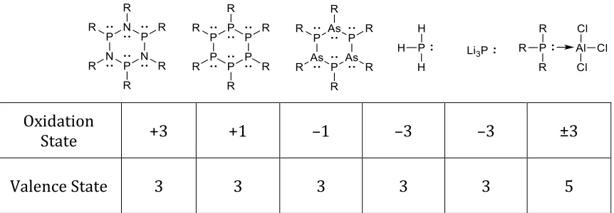
State +3 +1 –1 –3 –3 ±3
Valence State 3 3 3 3 3 5
Figure 1.1. Oxidation states of phosphorus in different molecules showing how oxidation state is not always consistent with valence state.
By examining the different phosphorus compounds shown in Figure 1.1, one
can see how oxidation state is not always in agreement with valence state. Oxidation
state itself is not always consistent and/or representative of the reactivity of a
compound. Comparing the first three compounds that contain pnictogens in a
very different oxidation states when they are similar in nature and bonding.
Comparing phosphine (PH3) and phosphide (Li3P), based on oxidation state rules,
they are assigned the same oxidation state (–3) when they are very different
compounds.
In the Macdonald group, we like using a more convenient model that is based
on the number of lone pairs in a given atom.13,14 In the case of phosphorus,
phosphorus with no lone pairs is in the +5 oxidation state (PV), phosphorus with one
lone pair is in the +3 oxidation state (PIII) and phosphorus with two lone pairs is in
the +1 oxidation state (PI). This model can be extended to other main group elements
and is particularly useful for group 13-15 main group elements. Figure 1.2 shows the
assignment of oxidation state for carbon using this model where carbon with no lone
pairs, one lone pair, two lone pairs, three lone pairs and four lone pairs are assigned
as carbon(+4), carbon(+2), carbon(0), carbon(–2) and carbon(–4), respectively.
+4 +2 0 –2 –4
Oxidation State
Figure 1.2. A more convenient model to assigning an oxidation state based on the number of lone pairs present on a given atom.
Every system has its shortcomings, and in this case, as the assignment depends
Lewis structure can be ambiguous as it’s possible to draw more than one plausible
structure for a given system. In the case of a carbodiphosphorane for example, two
phosphines are bound to a carbon centre as shown in Figure 1.3. The oxidation state
assignment can vary greatly depending on the way the structure is drawn. Lewis
structure is a tool to help illustrate basic connectivity of a given molecule, but to be
able to obtain more accurate electron density delocalization, computational methods
would be an ideal way of figuring out and assigning the presence or absence of lone
pairs on a given atom.15
+4 +2 0
Oxidation State
Figure 1.3. Different Lewis drawings of carbodiphosphorane showing how the assignment of oxidation state on the carbon centre can be different depending on the way the Lewis structure
is drawn.
1.3
Chemical Bonding: The Covalent Bond
The concept of a molecule dates to the seventeenth century, but it wasn’t until
the twentieth century that chemists got a better understanding of the structure of a
molecule. Gilbert Newton Lewis (1875–1946), was an American chemist that
discovered the covalent bond and the concept of an electron pair. He postulated the
track of electrons. Lewis also devised the octet rule which states that any
non-hydrogen atom will tend to form bonds until the octet rule is satisfied meaning it’ll be
surrounded by eight valence electrons.16,17
The Lewis model gave chemists a rationale for molecule formation, covalent
bonding and a way to help predict molecular geometries, but it didn’t answer the
question as to why molecules come together. Likewise, the octet rule was believed to
only work for the first two rows of the periodic table with the reasoning that atoms
in third shell or higher have access to d-orbitals, allowing for hybridization (orbital
mixing) yielding new orbitals capable of expanding beyond the octet rule. Firstly,
d-orbitals are high in energy and inaccessible to an atom like phosphorus and secondly,
there are examples of first and second row elements breaking the octet rule and
forming hypervalent compounds.18 Another downside to the Lewis model is the fact
that a Lewis structure of O2 (Figure 1.4) does not explain the paramagnetic
properties observed in liquid oxygen. This was the case until the introduction of
quantum mechanics.
Figure 1.4. A Lewis structure of a dioxygen atom (O2).
Molecular Orbital Theory (MO theory) is a method that describes a molecular
structure by combining atomic orbitals into orbitals that describe the bonding in a
dictates that the combination of these two orbitals would result in two molecular
orbitals, one bonding, and one anti-bonding. This is in accordance with Pauli
exclusion principle where no two electrons in a molecule can have the same set of
quantum numbers. Therefore, it’s necessary that the two originating atomic orbitals
be split into two molecular orbitals as shown in Figure 1.5.
Figure 1.5. Molecular orbital diagram of dihydrogen.
MO theory not only helps in rationalizing bonding but also explains why
bonding happens. Sharing of electrons can help stabilize a given molecule by bringing
down the energy of electrons as shown in Figure 1.5. Going back to the O2 example,
sketching the MO diagram (Figure 1.6) will make it clear why dioxygen is
paramagnetic. According to Hund’s rule, every orbital within a subshell is singly
occupied before an orbital is doubly occupied, thus, with two electrons to fill the
doubly degenerate π* orbital, each orbital must be filled with an electron before
Figure 1.6. Molecular orbital diagram of an O2.
1.4
Pincer Ligands
Early work in organometallic chemistry focused on monodentate and chelate
ligands; recent work, however, showed a lot of interest in pincer ligands due to their
versatility and ease of use. The term ‘pincer’ dates back to 1989 in which van Koten
used the term to describe tridentate ligands with an anionic carbon centre.19 Over the
past 15 years, the term pincer broadened to generally refer to any tridentate
(three-coordinate) ligand with adjacent binding sites that usually adopt a meridional (mer-)
geometry but can also be found with facial (fac-) geometry (butterfly-like) in some
the two geometries.20Figure 1.7 illustrates an [ONO] type ligand that is fluxional in
the sense that it can be present in a T-shaped geometry or a bent geometry, more
details to follow in section 1.5.21
Figure 1.7. Arduengo’s 10–As–3 T–shaped complex (mer-, left) and in the bent shape (fac-, right).
Due to their broadened definition, there is ambiguity regarding the
classification and nomenclature of pincer ligands. In a recent review, Peris and
Crabtree20 classify pincer ligands based on the charge and symmetry of the pincer
ligand. The term palindromic is used to describe symmetric donor arms (regardless
of the central donor), thus, coordinating atoms like [N,N,N], [O,N,O] and [P,C,P] are all
considered to be palindromic, as long as the substituents on terminal donors are the
same. In cases where the two terminal arms have differing donor atoms like [N,N,P],
or different substituents like [LN,N,NL’], the ligand is considered to be
non-palindromic. Regardless of the palindromicity of the pincer ligand, it can also be
further classified based on the overall charge of the ligand. It can be neutral (L3),
L3 XL2 X2L X3
Figure 1.8. Classification of pincer ligands based on the overall chargeof the pincer ligand, neutral (L3), anionic (XL2), dianionic (X2L) or trianionic (X3).
The use of pincer ligands with transition metals gained a lot of interest due to
the stability pincer ligands, the ease of tunability and cooperativity (through
non-innocent pincer ligands). Non-non-innocent ligands are redox active ligands that can
accept or lose electrons in its π-system resulting in significant change in the internal
bond distances of the ligand. This allows for the coordinated metal to maintain its
starting oxidation state or undergo reactivity that otherwise would not be possible.
Pincer ligands are very robust, which makes them a great choice in reactions that
require harsh conditions. Goldman and Brookhart22 reported the production of n
-alkanes using an iridium pincer catalyst (Figure 1.9) that can undergo extreme
reaction conditions, such as in the metathesis of n-decane that requires heating at 175
°C for nine days. Another example of the robustness of such systems is the Ni(II)
complex, Figure 1.9 (right), that is very thermally stable to the point that it can be
Figure 1.9. Goldman and Brookhart’s Iridium(III) catalyst (left) and Moulton’s Nickel(II) (right) are examples of robust metal pincer catalysts.
Pincer ligands also allow for tunability of the ligand framework, which gives
chemists a handle to manipulate the reactivity of the overall catalyst by modifying the
pincer ligand. The importance of pincer ligand design is illustrated in the Ni(II)
catalyst shown in Figure 1.10 that is used in the Sonogashia coupling between
terminal alkynes and alkyl halides. Dissociation of an amine sidearm is the rate
determining step of the reaction, a more labile amine (right) results in the catalyst
being active at room temperature, while a more rigid amine group (left) results in the
catalyst requiring temperatures exceeding 100 °C for the dissociation of the amine to
occur and for the catalyst to become active.24
Figure 1.10. An example of how the tuning of pincer ligand can affect the reactivity of the catalyst.
Another interesting aspect of pincer ligands is the possibility of introducing
chirality into the ligand design, allowing for enantioselective catalysis. Anionic
highly enantioselective transformations. The high kinetic stability of the resulting
catalysts allow for reduced catalyst loadings.25
Figure 1.11. Examples of chiral [N,N,N] pincer ligands.
Although pincer complexes are generally viewed as stable compounds, where
the ligand framework remains unchanged under harsh reaction conditions, there are
cases where the pincer ligand itself undergoes transformations resulting in unusual
reactivities. This occurs in cases where there is a great delocalization of electron
density over multiple aromatic rings resulting in a lowered HOMO–LUMO gap, that is
ligand based, allowing it to participate in electron transfer reactions.20 In such cases,
the ligand is considered to be “non-innocent” and is redox active. Figure 1.12
illustrates the reaction of a Ta(V) complex with a phenyl azide yielding in a nitrene
transfer onto the metal centre. The oxidation state of the tantalum centre does not
change, where tantalum maintains its preferred +5 oxidation state; however, the
pincer ligand goes from being a trianionic (X3) ligand to a monoanionic (XL2) ligand,
Figure 1.12. An example of a redox non-innocent ligand that allows Ta(V) undergo reaction with nitrene without changing the preferred oxidation state of the metal centre.
1.5
Pincer Complexes of Group 15 Elements and Their Role
in Modern Main Group Chemistry
Main group elements combined with various types of pincer ligands resulted
in some of the most interesting complexes to appear in the literature over the past
decade.25,27 In the 1980s, Arduengo was a pioneer in multidentate pnictogen
complexes.21,28–31 In the 1990s, he went on to synthesize the first stable carbene that
will be further discussed in Chapter 6 of this dissertation.32 Arduengo reported the
phosphorus complex of 5-aza-2,8-dioxa-3,7-di-tert-butyl-1-phosphabicy-
clo[3.3.0]octa-3,6-diene (ADPO), which is referred to as a 10–P–3 complex if it
assumes T–shaped geometry (Figure 1.13, left).30 The 10 denotes the number of π–
electrons in the system and the 3 refers to the number of coordination sites. If the
complex assumes a bent geometry, then there are 8 π–electrons in the system and the
Figure 1.13. Arduengo’s 10–P–3 T–shaped complex and its different resonance structures (left), and 8–P–3 bent complex (right).
Arduengo additionally reported the complexation of other pnictogens to the
same ligand (ADPnO). Arsenic and antimony both adapted the 10–Pn–3 T–shape
geometry21,28 while bismuth reacted with three equivalents of the ligand to yield a
20–Bi–9 complex (Figure 1.14, right).31 Upon treatment of ADPnO with silver,
Arduengo observed that, in the cases of arsenic and antinomy, the ligand system
maintained the T–shaped geometry resulting in a 10–Pn–4 complex, while in the case
of phosphorus, the coordination resulted in bent structure yielding an 8–Pn–4
system.33
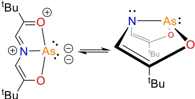
ADPnO complexes have interesting reactivities, starting with the ADSbO, as
treatment with hexafluoro-2-butyne afforded an unprecedented addition of a
substrate to hypervalent species as shown in Scheme 1.1, where two acetylenes add
across the antimony and carbon backbone. The reaction of ADSbO with
hexafluorobiacetyl results in the 4–coordinate adduct shown in the scheme below
(10–Sb–4) where two oxygens add across the antimony centre with an appended arm
of the tridentate ligand. In the case of arsenic, ADAsO reacts with
bis(trifluoromethyl)dithiete in a similar manner to that of the hexafluorobiacetyl
(with ADSbO) where the two sulfurs add across the arsenic centre; except that the
resulting complex is 5–coordinate (12–As–5).
Scheme 1.1. The Reaction of ADSbO with hexafluoro-2-butyne (right) and with hexafluorobiacetyl (left). The reaction of bis(trifluoromethyl)dithiete with ADAsO (bottom).
In light of recent advancements in main group chemistry in the activation of
chemists have been searching for other ways to activate small molecules using main
group elements. The ADPO complex that was first synthesized by Arduengo has been
recently investigated by Radosevich for possible catalytic activity.30,35,36 Practically,
tricoordinate P(III) compounds will tend to adopt a pyramidal geometry (Figure
1.15, left); however, through appropriate ligand design, it’s possible to deviate from
such geometry and by doing so, change the reactivity at the phosphorus centre.
Lowering the symmetry of a phosphine results in a smaller HOMO–LUMO gap that
results from destabilization of the HOMO and the stabilization of the LUMO. This gives
rise to a biphilic phosphorus centre capable of behaving as an electron donor and an
electron acceptor at the same site.35,36
Figure 1.15. Different geometries adapted by tricoordinate phosphorus: C3V, Cs and C2V respectively.
Radosevich demonstrated that Arduengo’s phosphine (ADPO) is capable of
activating N–H and O–H bonds of small molecules across the phosphorus centre.
Calculations show that this reaction does not undergo a concerted oxidative addition
via a three-centre transition; rather, an amine molecule would bind first to the
electrophilic phosphorus followed by a heterolytic cleavage of the N–H bond and a
proton transfer from N to P.36 ADPO is also capable dehydrogenating an ammonia–
Scheme 1.2. Radosevich’s synthesis of P(V)–H2 complex.
The resulting pentacoordinate P(V)–H2 complex can transfer hydrogens onto
an unsaturated organic substrate. The reaction was shown to be catalytic in the
presence of both ammonia–borane and azobenzene. A 10 mol% catalyst loading of
P(V)–H2 can transfer hydrogenate onto azobenzene substrate in yields exceeding
80% at room temperature. The difference between this method of transfer
hydrogenation and FLPs is that in the case of an FLP, the phosphorus acts as an
electron donor and requires the presence of a Lewis acid to act as an electron
acceptor. In the case of ADPO, however, both the electron donor and acceptor are on
the same site making it possible to perform two-electron redox transformations that
are observed in transition metal catalysts.35 The proposed mechanism for this
transformation is shown in Scheme 1.3 with an equilibrium between P(III) and P(V)
that illustrates the redox capability of the phosphorus centre. Other recent work by
Radosevich showed evidence of the formation of pentacoordinate phosphorus via a
concerted cyclic transition suggesting the potential of organophosphorus catalysis via
Scheme 1.3. Proposed mechanism of transfer hydrogenation catalysis of ADPO catalyst.
Pincer ligands have been used in the isolation of other various low valent main
group elements. In 2006, Cowley demonstrated that upon treating AsCl3 with SnCl2,
the arsenic is reduced to the arsenic(I) species (“AsCl”) that can be isolated by
treatment of the resulting suspension with an α,α’–diiminopyridine ligand (also
known as diiminopyridine, DIMPY and DIP), resulting in the arsenic(I) salt as shown
in Scheme 1.4.38 Ragogna later illustrated that the same ligand can be used in the
isolation of a phosphorus(I) salt by treatment of DIMPY ligand with PI3 resulting in a
P(I) centre and an I3– as the counterion (31P δ = 169 ppm). Ragogna reported that the
use of PCl3 and PBr3 resulted in either no reaction or in indiscernible mixtures.
Including a halide abstracting agent like cyclohexene in the presence of PCl3didn’t
with cyclohexene with much smaller yields (28% compared to >80% in the case of
PI3).39
Scheme 1.4. Examples of Group 15 low valent pincer complexes.
1.6
Pincer Complexes of Group 14 Elements and Their Role
in Modern Main Group Chemistry
The use of pincer ligands with group 14 elements dates back to 1985, before
the term pincer was even adopted, where Archer and co-workers reported the
synthesis of a tripyridine tin(II)chloride (Figure 1.16).39 Reid and co-workers
reported the synthesis of a germanium(II) salt of a triamine, pmdta
(MeN(CH2CH2NMe2)2) (Figure 1.16) by treatment of pmdta with 2 equivalents of
GeX2 (X = Cl, Br) yielding to the self-ionization of the GeX2 centre into a GeX+ and GeX3–
fragments.40 Although this is a more flexible ligand and is capable of adopting a facial
geometry, it rather adopts a planar meridional geometry.
As mentioned earlier, one of the reasons pincer ligands are attractive ligands
is the possibility to tune the ligand, thus, asymmetry can be introduced into the ligand
yielding a chiral metal centre. Evans and co-workers demonstrated this via the use of
a chiral ligand PYBOX (bis(oxazoline)pyridine) in the isolation of a chiral tin(II) Lewis
acid (Figure 1.17) that is capable of catalyzing aldol condensation reactions.42 With
10 mol% loading, aldol reactions can be performed between ethyl glyoxylate and
silylketene acetals to yield respective products in good yields in greater than 90% ee.
Figure 1.17. Evans’ tin(II) chiral Lewis acid complex.
DIMPY ligands have been important in development of group 14 low-valent
main group chemistry, Roesky reported that using such ligands, one is able to isolate
the self-ionization product of germanium(II) and tin(II) (Scheme 1.5).43 Nikonov
later reported that the treatment of a DIMPY-Ge(II) complex with two equivalents of
potassium graphite (KC8) in benzene results in a germanium(0) complex as
illustrated in Scheme 1.5.44 Other variants of the M(II) DIMPY (M = Ge, Sn) have also
Scheme 1.5. Roesky’s DIMPY-M(II) complex (M = Ge, Sn) and Nikonov’s reduced Ge(0) complex.
Although Sn(0) has not been synthesized in the same manner (reduction from
Sn(II) to Sn(0)) as in the case of germanium, Flock and co-workers were successful
using a different variant of DIMPY ligand with Sn[N(SiMe3)2]2 resulting in a
transamination reaction that yields a Sn(0) complex by eliminating two amine
equivalents (Scheme 1.6).47
Scheme 1.6. Mechanism of the transamination reaction of DIMPY ligand with Sn[N(SiMe3)2]2 to yield a Sn(0) complex.
Zaitsev’s group reported a different variant of dianionic tridentate complexes
reactive and can undergo reactions like oxidative addition and transition metal
coordination (Scheme 1.7).48–50 Coordination of germanium and tin complexes to
tungsten and molybdenum carbonyl compounds have been successful. In addition,
both germanium and tin complexes are capable of oxidatively adding small molecules
like MeI, Br2, and Ph2S2. Furthermore, DIMPY-Sn(II) complexes have been employed
in various transition metal coordination as a result of the work of Jambor and
co-workers.51,52
Scheme 1.7. Zaitsev’s tridentate complexes and reactivity.
1.7
Pincer Complexes of Group 13 Elements and Their Role
in Modern Main Group Chemistry
Pincer complexes of group 13 main group elements are more prominent in
literature in comparison to either group 14 and 15, particularly, after their recent
advancement as supporting ligands (metalloligand scaffold) for transition metal
catalysts.53An example of this is the use of metalloligand pincer scaffolds’ of group 13
elements that forms an overall pincer ligand with a group 13 element as the central
Scheme 1.8. Zwitterionic complexes containing ambiphilic pincer ligands.
The presence of a Lewis acid (e.g. boron or aluminium containing compounds)
at or near transition metals results in altered reactivity of the metal centre.57 Lewis
acids have been used in conjunction with transition metal catalysts as external
activators or co-catalysts. Only recently have Lewis acids been incorporated within
ligand motif resulting in ambiphilic ligands where the Lewis acid acts as a σ-acceptor
(Z-type) ligand. The different donor types can be described as L (2-electron donor), X
(1 electron donor) and Z (2-electron acceptor) type ligands. σ-acceptors can have
different goals in coordinating transition metals, they can be used to generate a
reactive electron-deficient metal centre and can also be used in cooperative
metal-ligand activation of small molecules.57–59 Having a group 13 element acting as a σ–
acceptor have mostly been investigated in use as an external activator or a co-catalyst,
but not until recently has it been investigated as part of a ligand scaffold to yield a Z–
type ligand (Figure 1.17).60 Z–type ligands are considered Lewis acids and when
studies show that the use of Lewis acids or Z-type donors in general at or near
transition metals result in increased reactivity of the metal centre.34,53,60,61
Figure 1.18. MO diagram depicting the difference between an L- and a Z-type ligand coordinating to a transition metal.
One example that illustrates this altered reactivity by incorporating a group
13 element is the work of Takaya and Iwasawa.53 The palladium(II) complex
proposed contains a group 13 main group element (E) within the ligand scaffold that’s
directly coordinated to palladium as illustrated in Figure 1.19. This catalyst is used
towards the hydrosilylation of CO2 and depending on the main group element
incorporated, the resulting reactivity of the catalyst was altered. Aluminium showed
the highest reactivity in the group 13 series and was much more reactive in
comparison to either gallium or indium. The aluminium containing catalyst exhibited
the highest catalyst activity reported for hydrosilylation of CO2 to be reported at the
time. This result shows a promising future for the development of new catalysts with


![Table 2.2. Selected bond distances (Å) of [NBn-BZIMPYGaCl2][GaCl4] (1), [(NBn-BZIMPY)(Cl)Ga—Fe(CO)4] (7), [iPrPDIAlCl2][AlCl4] (6) and Berben’s [iPrPDIAlCl]](https://thumb-us.123doks.com/thumbv2/123dok_us/1343983.1167264/78.612.141.507.224.498/table-selected-distances-bzimpygacl-bzimpy-iprpdialcl-berben-iprpdialcl.webp)
![Figure 2.5. Solid state structure of [(NBn-BZIMPY)(Cl)Ga—Fe(CO)4] (7). Thermal ellipsoids are shown at 50% probability level](https://thumb-us.123doks.com/thumbv2/123dok_us/1343983.1167264/79.612.240.415.83.192/figure-solid-state-structure-bzimpy-thermal-ellipsoids-probability.webp)