A Survey on Panoramic Image Matching by
Combining Harris with SIFT Descriptor
M. Hemalatha1, Pavithra.G2, Pavithran Gopal2, Pranesh Kumar K.N2, Radhika.K2
Assistant Professor, Dept. of CSE, Info Institute of Engineering, Anna University, Tamil Nadu, India1
B.E Student, Info Institute of Engineering, Anna University, Tamil Nadu, India2
ABSTRACT: The input taken from different viewpoints are stitched using this image stitching to produce visually realistic panoramic images. This approach allows wide baselines between images and non-planar scene structures. It is a mesh based framework to optimize alignment and regularity in 2D.Constructing the panoramic images, which are locally as perspective as possible and yet nearly orthogonal in the global view. Thu composition can be improved and achieve good performance on misaligned area. The key of constructing the measurable aerial panorama is to obtain the position and poseur of the aerial panoramic image. This approach will overcome the problem of measuring the aerial panoramic image, by obtaining the geographical location information of the image.
KEYWORDS: Image stitching, mesh based framework, composition, panoramic image.
I. INTRODUCTION
Nowadays, the usage of smart phones and digital cameras has been increased. Thus camera lens only have capability of capturing the limited of field of view for panoramic shooting mood. It is understood that panoramic image capturing is tedious process which consists of various factors. The main drawback of producing a large field of view for a close object, the shifting of camera is needed to capture various regions which lead to problem of constructing panoramic image. Images produced from different camera lens have multiple challenges. This problem can be eliminated by considering non ignorable base lines among multiple cameras. All previous image stitching methods uses simple camera rotation techniques. While taking these assumptions which leads to severe problem. Since the old methods use SIFT for correspondence which does not produce 360 degree panoramic image. We are proposing a Harris algorithm for corner point detection where we can achieve optimized and well constructed 360 degree panoramic image. Our main approach is using grid based frame work enhancing image alignment. Scale preservation is used to obtain alignment partially parallel to the image plane.
II. RELATED WORK
III. PROPOSED ALGORITHM
HARRIS ALGORITHM FOR CORNER POINTS DETECTION:
A corner can be defined as the intersection of two edges. The interest point is a point, a well defined position in an image. The quality of the corner detector is determined by its ability to detect the same corner in multiple similar images even under lightening, translation, rotation and other transforms.
FIG 1:INTENSITY WINDOW
In fig 1: We should easily recognize the point by looking at the intensity values within a small window. Shifting the window in any direction should yield a large change in appearance.
Harris corner detector gives a mathematical approach for determining the corner points:
6. Threshold on value of R. Compute non max suppression.
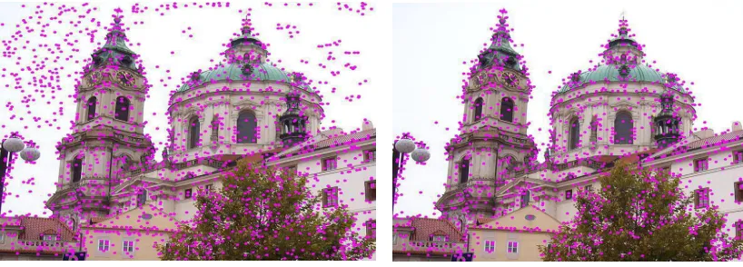
SIFT ALGORITHM TO FIND THE CORRESPONDENCE:
Scale invariant feature transformation (SIFT) algorithm is used to detect an describe local features and images. The feature description of the object is used to extract the interesting points of an object in an image. When an object is attempting to locate in a test image containing many other objects, the description extracted from the training image is used to identify that object. Even under the conditions such as scale, noise and illumination the feature extracted from the training image must have the capability to detectable.
There are 6 steps in this algorithm:
1. Scale space peak selection:
If it is a local extrema, it is a potential key point (key point represented best in that scale).The difference of Gaussian using two scales is given by
2. Key point localization:
To get more accurate results the potential key points are refined. To get the location of the local extrema, we use Taylor series. If the intensity at this extrema is less than a threshold value, then key point is rejected. This threshold is called contrast threshold. DoG has higher response for edges. So edges having higher response must be removed. Hessian matrix is used to compute the principal curvatures.
The Eigen values of H give a lot of information about the local structure around the key point. In fact, the Eigen values are the maximal and minimal principal curvatures of the surface D(x, y), i.e. of the DoG function, at that point. If the edge threshold ratio is less than 10 then the key point is discarded.
Fig 3: key point localization of an image
3. Orientation Assignment:
Orientation is assigned to each key point to achieve invariants to image rotation. A neighbourhood is taken around the key point location depending on the scale, gradient magnitude and direction is calculated in that region. An orientation histogram with 36 bins covering 360 degree is created.
Assign the dominant orientation as the orientation of the key point. In case of multiple peaks or histogram entries more than 0.8 x peak, create a separate descriptor for each orientation (they will all have the same scale and
location. Compute the gradient magnitudes and orientations in a small window around the key point – at the appropriate scale.
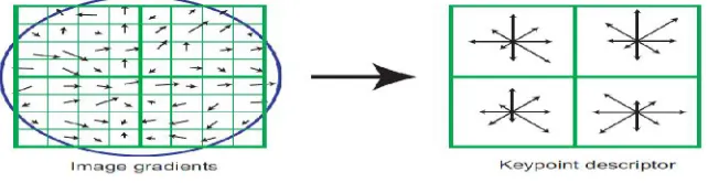
4. Key point Descriptor:
Consider a small region around the key point. Divide it into n x n cells (usually n= 2). Each cell is of size 4 x 4.Build a gradient orientation histogramin each cell. Each histogram entry is weighted by the gradient magnitude and a Gaussian weighting function with σ= 0.5 times window width. Sort each gradient orientation histogram bearing in mind the dominant orientation of the key point.
Fig 4: Key point descriptor
In fig 4 the image gradients are built and converted to key point descriptor.
We now have a descriptor of size r n 2 if there are r bins in the orientation histogram. Typical case used in the SIFT paper: r = 8, n= 4, so length of each descriptor is 128. The descriptor is invariant to rotations due to the sorting. For scale-invariance, the size of the window should be adjusted as per scale of the key point. Larger scale = larger window. The SIFT descriptor (so far) is not illumination invariant –the histogram entries are weighted by gradient magnitude. Hence the descriptor vector is normalized to unit magnitude.
5. Regularization:
6. Scale preservation:
Select one image as a reference view in order to avoid the degeneration problem. Only for few images this strategy works well. In order to reduce the alignment error the field-of-view could be increased for the image far from the reference. All the images are equally applied the scale constraint.
IV. PSEUDOCODE
Step 1: Compute x and y derivative of the image. Step 2: Compute products of derivates at every pixel.
Step 3: Compute the sum of the products of derivatives at each pixel. Step 4: Define at each pixel (x, y).
Step 5: Compute the response of the detector at each pixel. Step 6: Compute the threshold value R.
Step 7: End.
V. CONCLUSION
Thus a new image stitching approach has been presented. The mesh based model is more flexible, the moderate deviation could be accommodated in our method from the planar structures. Our method can preserve the local straightness in each image by combining feature alignment, regularization, scale preservation and other extra constraints. Thus composition is improved and achieves good performance on misaligned area. By projection, matching, back projection we are projecting aerial panoramic image according to the degree.
REFERENCES
1. J. Gao, S. J. Kim, and M. S. Brown, “Constructing image panoramas using dual homograhy warping”, in IEEE conference on computer vision and pattern recognition, vol. 2,pp.49-56,2011.
2. C. Harris and M.J. Stephens,”A combined corner and edge detector”, in Alvey vision conference, vol.6, pp.147-152, 2002.
3. C. Schmid, R. Mohr, C. bauckhage, “Evaluation of interest point detectors”, in International journal of computer vision, vol.9, pp.151-172, 2000.
4. P. Viola, W. Wells, “Alignment by maximization of mutual information”, in International conference on computer vision, vol.6, pp.16-23, 2001.
5. J. Zaragoza, T. Chin, Q. Tran, M. S. Brown, and D. Suter, “As-projective-as-possible image stitching with moving DLT,” IEEE Transaction and Pattern Anal. Mach. Intell., vol. 36, pp. 1285–1298, 2014.
6. V. Kwatra, A. Schodl, I. Essa, G. Turk, and A. Bobick, “Graphcut textures: image and video synthesis using graph cuts,” in ACM Transactions on Graphics, vol.22, pp. 277–286, 2003.
7. Y. Weiss, “Deriving intrinsic images from image sequences”, in International conference on computer vision, vol.11, pp.7-14, 2001.
8. M. Brown and D. G. Lowe, “Automatic panoramic image stitching using invariant features,” International Journal of Computer Vision, vol. 74, pp. 59–73, 2007.
9. W.Y. Lin, L. Liu, Y. Matsushita, K.-L. Low, and S. Liu, “Aligning images in the wild,” in IEEE Conference on Computer Vision and Pattern Recognition, vol.16, pp.145-162, 2012.
10. S. M. Seitz, B. Curless, J. Diebel, D. Scharstein, and R. Szeliski, “A comparison and evaluation of multi-view stereo reconstruction Algorithms,” in IEEE Conference on Computer Vision and Pattern Recognition, vol.4, pp.519–528, 2006.
11. [6] Y. Boykov, O. Veksler, and R. Zabih, “Fast approximate energy minimization via graph cuts,” IEEE Trans .Pattern Anal. Mach. Intell., vol. 23, pp.1222–1239, 2001.
12. Yu wang , “Image matching algorithm based on sift and wavelet transform”, journal of Beijing institute of technology, vol.5, pp.456-468, 2009.
BIOGRAPHY