V Fired ATMEGA 2560 Microcontroller Based
Mobile Robot for the Detection of Toxic and
Nuclear Waste
M.Pradeep Kumar1,R.Nandhini2, D.Nethra2, M.Sharmila2 ,C.Soundharya2.
Assistant Professor, Dept. of ECE, The Kavery Engineering College, Salem, Tamilnadu, India1 UG Students, Dept. of ECE, The Kavery Engineering College, Salem, Tamilnadu, India2
ABSTRACT: The accompany of robotics with wireless communication technologies are rapidly spreading in too many new areas, The toxic detection in remote area by using robotics can useful to avoid human interference with high toxic like carbon monoxide, chlorine, nitrogen dioxide and nuclear radiation which spare human life. In this paper we proposed a mobile robot which motion can be controlled in all the direction by commanding it and by using appropriate sensor the toxic and nuclear radiation can be detected. Also WIFI and GSM Module communicate the results to control board unit (CBU). ATMEGA 2560 V bird robots have with special sensors are used here to fulfill our desired task. The output of the robots are connected to particular webpage so all can able to see the result.
KEYWORDS: CBU (Control Board Unit); WPAN; IOT Internet of things; ATMEGA 2560
I. INTRODUCTION
The toxic gas like H2, LPG, CH4, CO and Propane in a remote location always causes poisonous to humans and sometimes it takes human lives. To deal with a particular poisonous gases in remote area a high intelligent mobile robots are utilised. This paper proposed a wireless robot which can be controlled through remote control using zigbee module and navigates around the areas and tries to detect the obstacles, toxic gases, fire, Nuclear radiation and chemicals.
The International Organization for Standardization gives a definition of robot in ISO 8373: "an automated controllable, reconfigurable, multi utility, manipulator programmable in three or more axes, which may be either fixed in place or mobile for use in industrial automation applications."Actual robot design seems to be not possible for the common as the equipments and the skill need is expensive and hard to learn. Building prototype of actual robot however is still possible to demonstrate the importance of the intended application. In this research, Zigbee wireless technology is used together with robotic application to illustrate the effectiveness of mobile robot . Zigbee is one of the new technology designed to Wireless Personal Area Networks (WPAN) based around the new and emerging IEEE 802.15.4 standard. As such, Zigbee has great effect for public into personal robotics for control purposes, for telemetry to name a few applications. This paper will show the development of a merged system of mobile robotic concept. Zigbee is defined as a high level communication protocols using small, low-power digital radios based on the IEEE 802.15.4-2003 standard for wireless personal area networks (WPANs).Successful implementation of wireless mobile robot using Zigbee protocol will serve as a basics for building actual search and capable of performing dangerous and almost impossible missions for human.
The ATMEGA 2560 robot with two DC motor controls are used to mobile the chase to particular location. By commanding the robot through Zigbee module the direction of robot can be possible. The DC motor is connected by a shaft and rotating motor in clockwise and anticlockwise the motion of the robots can be controlled. The sensors connected in chase of the robot detect the gas and nuclear radiation present in the location.The zigbee module and GSM module communicate the result to the control board unit updated to the webpage.
II. LITERATURESURVEY
Several applications have been reported in areas a water and air monitoring, gas leakage detection, explosives, drugs or people detection and demining tasks, among others.Many robotic platforms (i.e. hardware and software) has ,been proposed to carry out an odor detection task however in this field, this remains an open research. This research requires the development and evaluation of a robust mobile robotic, platform which supports an toxic and nuclear sensory unit, as well as some development tools like PC communication, data saving.This work has been focused on this topic. A Labview virtual instrument was developed to allow the data acquisition from sensors as well as motor commands, via serial port.
III.PROPOSED ALGORITHM
Description of the Proposed Systems:
Aim of the proposed system is to detect the toxic gases, flames, obstacles and nuclear radiation in remote area and the result of the toxic gases is displayed in the web pages by using IOT also Zigbee and GSM modules are implemented for communication. The proposed system consists of three main modules..
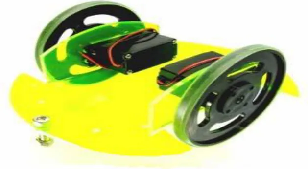
Robot Base and Motion Control
Mobile robot is the base platform that carries the load of the robot. Robot base design is depending on the application of the robot. If the robot move on the rough surface the material and size of the base must be suitable. The robot base must be capable to carry microcontroller circuit ,XBEE circuit, LCD device, 6V battery holder and 2 pieces of 9V battery. The 6V servo motor is enough to carry this load. The Left motor and right motor of the robot is connected to the shaft and the rotation of the dc motor choose the chase to move in specified direction.The table no.1 below shows the direction control of robots
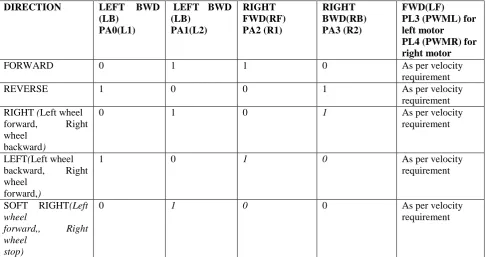
Table No. 1:Motion Control
DIRECTION LEFT BWD
(LB) PA0(L1)
LEFT BWD (LB) PA1(L2) RIGHT FWD(RF) PA2 (R1) RIGHT BWD(RB) PA3 (R2) FWD(LF) PL3 (PWML) for left motor PL4 (PWMR) for right motor
FORWARD 0 1 1 0 As per velocity
requirement
REVERSE 1 0 0 1 As per velocity
requirement RIGHT (Left wheel
forward, Right wheel
backward)
0 1 0 1 As per velocity
requirement
LEFT(Left wheel backward, Right wheel
forward,)
1 0 1 0 As per velocity
requirement
SOFT RIGHT(Left wheel
forward,, Right
wheel stop)
0 1 0 0 As per velocity
SOFT LEFT(Left wheel
stop, Right wheel forward,)
0 0 1 0 As per velocity
requirement
SOFT RIGHT 2 (Left
wheel stop, Right wheel
backward)
0 0 0 1 As per velocity
Requirement
SOFT LEFT 2 (Left wheel backward, Right
wheel stop)
1 0 0 0 As per velocity
Requirement
HARD STOP 0 0 0 0 As per velocity
Requirement SOFT STOP (Free
running stop)
X X X X As per velocity
Requirement
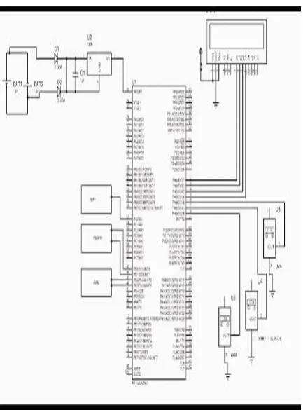
The rotation of the motor is commanded by controller which already it was programmed in ATMEGA 2560. The motor is connected to port c of microcontroller where it is connected to the pin 53 to 60.
Motion control involves direction control and velocity control. Motors are controlled by L293D dual motor driver which can provide up to 600mA of current to each motor. To change the direction of the DC motor, appropriate logic
levels (High/Low) are applied to L293D’s direction control pins.
Fig 1 Robot Base and Motion Control
Sensor
changes in the direction can be possible by giving command in the microcontroller. Sensor’s current sensing element is located between robot’s ground and the battery ground.
When no current is flowing through the sensor, it gives 2.5V output. This output value reduces by 185mV / ampere of current flow if 5 Ampere type sensor is installed. If 20 Ampere type sensor is installed value is reduced by 100mV / ampere. This sensor is an optional accessory. When this sensor is absent its sensing path is shorted with 0 ohm resistor. For more information on the sensor operation, refer to its datasheet which is located in the “Datasheets” folder of the documentation CD.locity control is done using Pulse Width Modulation (PWM).
Fig 2 CO Gas Sensor
A camera is attached to find the path of the robot and obstacles in the path where the robot is passing.
Notification System:
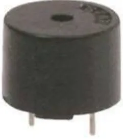
Buzzer LCD Display
A buzzer device, which may be mechanical, electromechanical, or piezoelectric. A buzzer or beeper is an audio signaling device, which may be mechanical, electromechanical, or piezoelectric. Typical uses of buzzers and beepers include alarm devices, timers and input such as a mouse click or keystroke.
Buzzer is an integrated structure of electronic transducers, DC power supply, widely used in computers, printers,copies,alarms, automotive electronic equipment, telephones, timers and the other electronic products for sound devices. Active buzzer 5V Rated power can be directly connected to this section dedicated sensor expansion module and the board in combination, can complete a simple circuit design, to "plug and play."
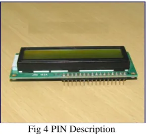
LCD
A liquid crystal display (LCD) is the thin, flat electronic visual display that uses the light modulating properties of liquid crystals (LCs). LCDs do not emit light directly. Liquid crystal displays (LCDs) are a passive display technology. This means it do not emit light instead, it use the ambient light in the environment By manipulating this light, it display images using very little power. it had made LCDs are the preferred technology whenever low power consumption and compact sizes are critical. It is used in a wide range of applications, including computer monitoring, television, instrument panels, aircraft cockpit displays and etc. it is common in consumer devices such as video players, gaming devices, clocks, watches, calculators, and telephones. LCDs are contain to displaced cathode ray tube (CRT). LCDs are usually more compact, lightweight, portable, less expensive, more reliable, and easier on the eyes.
Fig 4 PIN Description
Table 2:pin connection
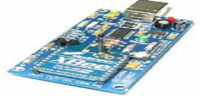
Zigbee:
In this application for the wireless mobile robot to regular Xbee is selected. Transmit power output is rated at 1mW with an operating frequency of 2.5GHz with operating current running around 45-50 mA and RF data rate of 250kbps. The XBee-Pro edition runs at a 10mW output power, enabling it to transmit much further. The XBee module is low power, small and easy to integrate into any project with short-range wireless communication.
Fig 5 Zigbee module
ATMEGA 2560
Fig 6 pin configuration of ATMEGA 2560
IV.CONCLUSION AND FUTURE WORK
In this study, a very useful fall detection method was proposed based on the real-time calculation of temprature,gas,humidity. For calculating the temprature,gas,humidity in real time, an mobile robotics system that consists of a three sensor and built-in-ATMEGA2560 was developed.Here we used the IOT module for the communication purpose in the GSM and WI-FI module also fixed.For the system communication purpose we are used the zigbee module.In this method containing the DC motors.It contains 4 relay for movable purpose.When the command is passsed from the system at the time the robot adopt to response on that command.Then its detected the temprature,gas,humidity range from the environment and the message is passed through the IOT module to user.The user response to act the message and to avoid such a accident.
REFERENCES
[1] E. Kelasidi, K. Y. Pettersen, J. T. Gravdahl, and P. Liljeb¨ack, “Modeling of underwater snake robots,” in Proc. IEEE Int. Conf. Robotics and Automation, Hong Kong, China, May, Jun. 2014.
[2] K. Mclsaac and J. Ostrowski, “A geometric approach to anguilliform locomotion: modelling of an underwater eel robot,” in Proc. IEEE Int. Conf. Robotics and Automation, Detroit, MI, May 1999.
[3] A. J. Wiens and M. Nahon, “Optimally efficient swimming in hyperredundant mechanisms: control, design, and energy recovery,” Bioinspi-ration & Biomimetics, vol. 7, no. 4, 2012.
[4] M. Porez, F. Boyer, and A. J. Ijspeert, “Improved lighthill fish swimming model for bio-inspired robots: Modeling, computational aspects and experimental comparisons,” Int. J. Robot. Res., vol. 33, no. 10, pp. 1322–
1341, 2014.
[6] H. Yamada, S. Chigisaki, M. Mori, K. Takita, K. Ogami, and S. Hirose, “Development of amphibious snake-like robot ACM-R5,” in Proc. 36th Int. Symp. Robotics, Tokyo, 2005.
[7] P. Liljeb¨ack, Ø. Stavdahl, K. Pettersen, and J. Gravdahl, “Mamba – A waterproof snake robot with tactile sensing,” in Proc. IEEE/RSJ Int. Conf. Intelligent Robots and Systems, Chicago, IL, Sep. 2014.
[8] L. Lapierre and B. Jouvencel, “Path following control for an eel-like robot,” in Proc. Oceans 2005 - Europe, Brest, France, Jun. 2005. [9] J. Guo, “A waypoint-tracking controller for a biomimetic autonomous underwater vehicle,” Ocean Engineering, vol. 33, no. 17-18, pp. 2369– 2380, 2006.
[10] P. Liljeb¨ack, I. U. Haugstuen, and K. Y. Pettersen, “Path following control of planar snake robots using a cascaded approach,” IEEE Trans. Control Syst. Technol., vol. 20, no. 1, pp. 111–126, 2012.