MAGNETIC ATTITUDE CONTROL FOR NANO-SATELLITES
SYAHRIM AZHAN BIN IBRAHIM
A project report submitted in partial fulfilment of the requirements for the award of the degree of
Master of Engineering (Electrical - Mechatronics and Automatic Control)
Faculty of Electrical Engineering Universiti Teknologi Malaysia
iii
To my parents, my beloved wife Norhaliana
and my wonderful daughters Sarah and Sofia for being there for me throughout the
iv
ACKNOWLEDGEMENT
Praise to Allah SWT the most merciful and the most compassionate for the guidance and knowledge bestowed upon me, for without it I would not have been able to come this far. Peace is upon him, Muhammad the messenger of Allah.
I wish to express my sincere appreciation to my supervisor, Dr. Mohamad Noh bin Ahmad @ Mohd Sanif for his encouragements, guidance and motivations throughout the year.
My sincere appreciation also extends to all my colleagues at Pusat Angkasa Negara, for the understandings and support.
v
ABSTRACT
The active magnetic attitude control technique is a recognized attitude control option for small satellites operated in Low Earth Orbit (LEO). The purpose of this thesis is to control a nano-satellite that is operated in LEO so that it always pointing toward the Earth. Two options of control algorithms have been considered for a gradient satellite. The first control is a passive type, structured for the
vi
ABSTRAK
vii
TABLE OF CONTENTS
CHAPTER TITLE PAGE
ACKNOWLEDGEMENT ABSTRACT
ABSTRAK
TABLE OF CONTENTS LIST OF TABLES LIST OF FIGURES
LIST OF ABBREVIATIONS NOMENCLATURE iv v vi vii x xi xiii xiv
1 INTRODUCTION
1.1 General Overview
1.2 Attitude Control System (ACS) 1.3 Nano-Satellites
1.4 Problem Statement 1.5 Objectives of Project 1.6 Scope of Project 1.7 Methodology 1.8 Thesis Outline
viii
2 LITERATURE REVIEW
2.1 Gravity Gradient Stabilization 2.2 Magnetic Attitude Control System 2.3 Magnetic Torques
2.4 Magnetometer 2.5 Summary
7 9 12 13 14 3 4 BACKGROUND THEORIES 3.1 Orbital Period
3.2 Satellite Kinematics and Dynamics 3.2.1 Coordinate Reference System 3.2.2 Satellite Kinematics
3.2.3 Satellite Dynamics 3.3 External Disturbances 3.4 The Geomagnetic Field 3.5 Control Theory
3.5.1 State Space Representation 3.5.2 System Stability
3.5.3 Passive Control
3.5.4 Active Control via PD Controller 3.6 Summary
MODELLING AND DESIGN
4.1 Modelling of Simplified Geomagnetic Field 4.2 Satellite Configuration
4.3 Modelling of External Disturbances 4.4 Dynamic Model of Gravity Gradient Satellite – Satellite A
4.5 Modelling of Magnetic Attitude Control Structure – Satellite B
ix
5 RESULTS AND ANALYSIS
5.1 Simplified Geomagnetic Field 5.2 Satellite Parameters
5.3 Attitude Response of Purely Gravity Gradient Satellite
5.3.1 Pole Placement
5.4 Attitude Response of Gravity Gradient Satellite with Magnetic Attitude Control 5.4.1 Pole Placement
5.5 Discussion
34 36 37
37 38
41 41
6 CONCLUSION & RECOMMENDATION
6.1 Conclusion 6.2 Recommendation
44 45
REFERENCES 47
x
LIST OF TABLES
TABLE NO. TITLE PAGE
4.1 Mass moment of inertia values 29
5.1 Orbital Parameters 35
5.2 Satellite Parameters 36
5.3 at i = 53° and h = 540km 39
5.4 Control parameters of Satellite B 39
6.1 Attitude performance of both Satellite A and Satellite B
xi
LIST OF FIGURES
FIGURE NO. TITLE PAGE
1.1 Satellite body coordinate system 1
1.2 A magnetic attitude control system to achieve a proper orientation for Earth-imaging
2
1.3 General closed loop system for satellite attitude control
3
1.4 CubeSats order from left to right: 1U, 1.5U, 2U, and 3U
4
2.1 UoSat 8
2.2 Stability region for gravity gradient stabilized satellite
9
2.3 Generated torque vector for a satellite in geomagnetic field
11
2.4 Schematic diagram of a magnetic torque 12
2.5 Magnetic torque rod from CubeSatShop.com 13
2.6 Smart Digital Magnetometer HMR-2300 14
3.1 Circular orbit 16
3.2 Nadir pointing satellite 18
3.3 The Earth‟s geomagnetic field 22
3.4 Full gravity gradient stabilized satellite 25 4.1 Purely gravity gradient satellite (Satellite A) 28 4.2 Gravity gradient satellite with 3 magnetic
torquers (Satellite B)
28
xii
geomagnetic field along five orbits with 53° inclination, at 540km altitude
5.2 Geomagnetic field vector components along LVLH coordinate system
36
5.3 Performance of roll, pitch and yaw of Satellite A
37
5.4 Poles placement in S-plane for transfer function of Satellite A
38
5.5 Performance of roll, pitch and yaw of Satellite B
40
5.6 Poles placement in S-plane for transfer function of Satellite B
41
5.7 Roll attitude performances 41
5.8 Pitch attitude performances 42
xiii
LIST OF ABBREVIATIONS
ACS - Attitude Control System ECI - Earth Centered Inertial LEO - Low Earth Orbit
xiv
NOMENCLATURE
B - Geomagnetic field vector [𝑇𝑒𝑠𝑙𝑎]
M - Satellite‟s magnetic dipole moment vector [Am2]
𝑚E - Mass of the Earth [𝑘𝑔]
𝑚S - Mass of the satellite [𝑘𝑔]
G - Universal constant of gravitation, 𝐺 = 6.669×10⁻¹¹𝑚3𝑘𝑔−1𝑠−2 r - Geocentric distance [m]
µ - Earth gravitational constant, 𝜇 = 3.986×10¹⁴𝑚3𝑠−2 i - Inclination [deg]
𝑟𝑒 - The Earth radius, 𝑟𝑒 = 6378 𝑘𝑚
ROrbit - Orbit radius [𝑚] ϕ - Roll attitude [𝑑𝑒𝑔] θ - Pitch attitude [𝑑𝑒𝑔]
ψ - Yaw attitude [𝑑𝑒𝑔]
Ix, Iy, Iz - Satellite‟s moment of inertia [𝑘𝑔𝑚2]
𝜔x, 𝜔y, 𝜔z - Satellite‟s body angular velocity[rads-1]
𝜔̇x, 𝜔̇y, 𝜔̇z - Satellite‟s body angular rate [rads-2] 𝑇𝑥, 𝑇𝑦, 𝑇𝑧 - External torque [𝑁𝑚]
𝑇𝑐𝑥, 𝑇𝑐𝑦, 𝑇𝑐𝑧 - Control torques [𝑁𝑚] 𝑇𝑑𝑥,𝑇𝑑𝑦,𝑇𝑑𝑧 - Disturbance torque [𝑁𝑚]
xv
𝜇 𝑓 - Magnetic moment of the Earth,𝜇𝑓=7.96×10¹⁵ 𝑊𝑏∙𝑚−1
𝑐𝑝𝑎 - Centre of aerodynamic pressure [𝑚] 𝑐𝑝𝑠 - Location of solar force [𝑚]
𝑐𝑔 - Satellite‟s centre of gravity [𝑚] D - Residual dipole [𝐴 𝑚2]
F - Force [𝑁]
1
CHAPTER 1
INTRODUCTION
1.1 General Overview
Some satellite subsystems require a stable satellite to carry out its mission. For example radio communications will require less power if the antenna is made to point toward Earth and solar panels can increase power output if properly directed towards the Sun. Specific payloads like a camera require a stable platform on which the satellite has to have 3-axis control namely roll, pitch and yaw. The orientation of the satellite in space is called its attitude. Figure 1.1 shows a satellite with an output of roll, pitch and yaw attitude angles.
Figure 1.1: Satellite body coordinate system
2
torque. These torques significantly affect the orbital and attitude motions of the satellite by creatingundesirable motions, hence counterbalance action is required in the form of attitude control system (ACS). Therefore ACS should have the ability to determine the current attitude, determine the error between the current and desired attitudes and apply torques to remove the error.
This project intends to look into passive and active ACS based on gravity gradient control and magnetic attitude control respectively. Firstly mathematical models of a gravity gradient satellite will be determined. Subsequently this model will be equipped with electromagnetic based device called magnetic torques for active control. Performance of both designs will be tested and simulated in the presence of a simplified geomagnetic field model as well as disturbance torques model using MATLAB/SIMULINK.
1.5 Attitude Control System (ACS)
Attitude Control System (ACS) is an important subsystem in a satellite which functions to stabilize the satellite, orients the satellite in desired directions as well as sensing the orientation of the satellite relative to reference (i.e. inertial) points. Figure 1.2 illustrates a nano-satellite named as M-Cubed designed by University of Michigan's Student Space Systems Fabrication Lab which is configured to align one of its axes with the local Earth magnetic field direction.
Figure 1.2: A magnetic attitude control system to achieve a proper orientation for
3
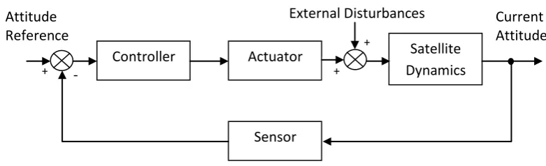
Design of ACS varies according to mission of satellites and their attitude requirement. The basic types of control systems are spin, three-axis active and passive or gravity gradient control systems. In general, an ACS consists of four major functional parts: sensor, controller, actuator and satellite dynamics. The sensor determines satellite attitude. The controller programs the electronic signals in a correct sequence to the actuator which is torque producing elements that can rotate the satellite about its center of mass. The resulting motion or dynamics is then monitored by the sensor which closes the loop of ACS as shown in Figure 1.3.
In this work the satellite‟s orbit is set at LEO that is a distance between 160 kilometers and 2,000 kilometers above the Earth‟s surface. Its mission is specified to be a nadir pointing mission meaning one of the axes will point toward the Earth. The other two axes will be normal to the orbital plane and towards the satellite‟s orbital motion respectively. This work will specifically look into a gravity gradient stabilized satellite which is a passive system as well as magnetic attitude system which is an active system.
Figure 1.3: General closed loop system for satellite attitude control
1.3 Nano-Satellites
Nano-satellite is applied to an artificial satellite with a mass between 1 and 10kg. Majority of development comes from academia, and normally they follow CubeSat specification. The concept of standard satellite type, 1-kg „CubeSat‟ Nano-satellite had been introduced since 1999 with the main goal to promote a low cost
Attitude Reference Current Attitude External Disturbances + -
+ Controller
Sensor
Satellite Dynamics Actuator
4
platform for space development and serve as educational tool for university student to design and develop a fully working satellite. The standard 10×10×10 cm basic CubeSat is often called a "1U" CubeSat meaning one unit. CubeSats are scalable along only one axis, by 1U increments. Hence they are CubeSats as "2U" CubeSat (20 × 10 × 10 cm) and "3U" CubeSat (30 × 10 × 10 cm). Figure 1.4 shows four different types of CubeSats.
Constraints on the technical capacity of the people that are involved, cost limitation as well as lack of size mean restraint in complexity of the design, weight and energy resource that a nano-satellite can carry to name a few. Therefore requirements of the systems on board together with payloads that can be carried are preferably low cost, low energy with simple hardware requirement. Accordingly requirement for attitude control is moderate. ACS using gravity gradient and magnetic attitude control methods are some of the techniques that are popular and highly used whether alone or with a combination with other actuators.
Figure 1.4: CubeSats order from left to right: 1U, 1.5U, 2U, and 3U. (Web 2, 2013)
1.4 Problem Statement
5
systems that have combination of actuators such as momentum wheel and magnetorquers together which could improve the angular orientation of the satellite as shown by Candini et al. (2012) and Dechao et al. (2013). However, high failure rate of nano-satellites when they are in orbit, show precautions are required for usage of a system that require high processing on the CPU (Web 3, 2013). Therefore applying a moderate system that has been applied and proven successful in previously launched micro-satellites could increase the probability of having successful mission. The problem considered in this thesis consists of stabilizing the attitude of a nadir pointing nano-satellite in LEO through usage of a passive gravity gradient stabilization or affiliated with magnetic stabilization using magnetic torques. The techniques need to consider a variety of disturbances that is anticipated in the orbit and exploit them in satellite dynamics model.
1.5 Objectives of Project
The objectives of this project are as follows: (i) To model a simplified geomagnetic model
(ii)To establish the mathematical models of a gravity gradient satellite equipped with three magnetic torquers
(iii)To control the attitude of the satellite in the presence of the disturbances by using the magnetic torques
(iv)To compare the performance of both the passive and active ACS design which are based on purely gravity gradient and magnetic control respectively
1.6 Scope of Project
The work undertaken in this project is limited to the following aspects: (i) Only nano-satellites are considered
(ii)Satellite‟s mission: Earth pointing small satellite at Low Earth Orbit (LEO) (iii)A gravity gradient satellite equipped with three magnetic torquers as
6
(iv)Simulation work using MATLAB/SIMULINK as a platform to evaluate the attitude control algorithms
1.7 Methodology
The research work undertaken in the following five development stages: (i) Literature review.
(ii) Mathematical model of a simplified geomagnetic field.
(iii) Establish mathematical models of a gravity gradient satellite with three magnetic torques as actuators in active system.
(iv) Consider in orbit external disturbances.
(v) Perform simulation using MATLAB/SIMULINK. (vi) Comparative study and future work.
1.8 Thesis Outline
The rest of this thesis contains another five chapters. Chapter 2 reviews literatures related to this work. The focus is on the gravity gradient technique and magnitude attitude control technique. Chapter 3 briefly describes theories used in modeling a simplified geomagnetic field, satellite‟s kinematics and dynamics and external disturbance torques.
47
REFERENCES
Bender, E. (2011). An Analysis of Stabilizing 3U CubeSats Using Gravity Gradient Techniques and a Low Power Reaction Wheel. California Polytechnic State University, US.
Candini, G.P., Piergentili, F. and Santoni, F. (2012). Miniaturized attitude control system for nanosatellites. Acta Astronautica 81 325–334.
Chobotov V.A. (1991). Spacecraft Attitude Dynamics and Control. Krieger Publishing Company.
Curtis, H.D. (2005). Orbital Mechanics for Engineering Students. Elsevier Butterworth-Heinemann.
Dechao, R., Tao, S., Lu, C., Xiaoqian, C. and Yong, Z. (2013). Attitude control system design and on-orbit performance analysis of nano-satellite—“Tian Tuo 1”. Chinese Journal of Aeronautics (2013).
Kaplan, M.H. (1976). Modern spacecraft dynamics and control, John Wiley & Sons, New York.
McLean, S., Mcmillan, S., Maus, S., Lesur, V., Thompson, A. and Dater, D. (2004). The
US/UK World Magnetic Model for 2005-2010. NOAA Technical Report
NESDIS/NGDC-1.
Martel, F., Pal, P.K. and Psiaki, M. (1988). Active magnetic control system for gravity gradient stabilized spacecraft. Proceeding of the 2nd AIAA/USU Conference on Small Satellites, Utah State University.
Psiaki, M. L. (2001). Magnetic torquer attitude control via asymptotic periodic linear quadratic regulation. Journal of Guidance Control and Dynamics, 24(2), 386-394.
Sidi, M.J. (1997). Spacecraft dynamics and control. Cambridge University Press.
Sofyali, A. and Aslan, A.R. (2011). Magnetic Attitude Control of Small Satellites: A Survey of Applications and A Domestic Example. IAA-B8-1312, 8th IAA Symposium on Small Satellites for Earth Observation, Berlin, Germany.
Steyn, W. H. (2001). Magnetic Attitude Determination And Control for Low Earth Orbiting Small Satellites. Department of Electrical and Electronic Engineering. University of Stellenbosch. http://staf.ee.sun.ac.za/whsteyn/papers/magsat.pdf.
48
Suhadis, N.M. and Renuganth V. (2010). Comparison Study on Low Cost Satellite Magnetic Attitude Control Options. International Review of Aerospace Engineering. Vol.3, N.3 (2010).
Suhadis, N.M. (2011). Magnetic Attitude Control Options for Earth Pointing Small Satellite. Ph.D. Thesis. Universiti Putra Malaysia.
Wisnieski, R. and Blanke, M. (1999). Fully magnetic attitude control for spacecraft subject to gravity gradient. Automatica, Vol. 35, 1201 – 1214.
Web 1 (2013), http://www-personal.umich.edu/~mjregan/MCubed/Pages/O&C.html
Web 2 (2013), www.cubesatkit.com
Web 3 (2013), http://en.wikipedia.org/wiki/List_of_CubeSats
Web 4 (2013), http://en.wikipedia.org/wiki/Gravity-gradient_stabilization
Web 5 (2013),
http://microsat.sm.bmstu.ru/e-library/Missions/Brief/Uosat/UoSAT%20OBDH%20Hardware%20Overview.htm
Web 6 (2013),
http://www.cubesatshop.com/index.php?option=com_virtuemart&Itemid=69
Web 7 (2013),
http://www51.honeywell.com/aero/common/documents/myaerospacecatalog-documents/Missiles-Munitions/HMR2300.pdf
Web 8 (2013),
http://www.star-oddi.com/news/newsletters/issues/2009/11/04/default.aspx
Web 9 (2013),