Experiments on Melt-Coolant Interaction Processes, including Steam Explosions
G. Albrecht, W. Cherdron, U. Imke, H. Jacobs*, A. Kaiser, W. Schütz, H. Will Forschungszentrum Karlsruhe GmbH (FZK)
Institut für Reaktorsicherheit IRS
(*Institut für Kern- und Energietechnik IKET) Postfach 36 40
D-76021 Karlsruhe, Germany
ABSTRACT
Steam explosions (or vapor explosions) are a safety concern during analysis of LWR core melt accidents that have an extremely low probability of occurrence. Conceptually steam explosions might damage safety relevant components of the plant. Improved analysis tools are being developed for such events in order to better understand their role during the accident and to demonstrate larger safety margins where possible. For this, an improved insight into the phenomena involved as well as reliable and relevant experimental data are required. We report here the main results of the PREMIX series of experiments in which the premixing phase of steam explosions was studied. We also report about the very first results of a new series of experiments, ECO, which serves to measure explosion pressure and mechanical energy release in a confined geometry.
1. INTRODUCTION
1.1 General overview and motivation
Steam explosions occur when a large amount of heat is transferred to a vaporizable liquid at a temperature far above its boiling point and at such a rate that the system cannot expand fast enough to convert all the heat transferred into heat of vaporization. They are encountered often when liquids of very different temperatures are intermixed accidentally, e.g. in the foundry or paper pulp industries or during transport of liquefied natural gas across water. On the other hand, quenching of molten materials in water pools is a widely used technique to granulate and cool effectively these materials. This dualism indicates the necessity of a careful treatment of the problem. Both types of interaction are called thermal interaction.
Steam explosions are a matter of concern in nuclear reactor safety since long (for more details see the review papers /1, 2, 3, 4/). Several reactors have been destroyed by steam explosions that occurred by accident (e.g. NRX, SL-1, Tschernobyl-4) or in spectacular destructive tests (e.g. SPERT-1). In all these cases the nuclear fuel was initially distributed within the coolant by intention (for cooling), and an accidental nuclear power excursion led to its rapid melting which produced the initial conditions for the steam explosions. Such power excursions are eliminated by design in modern nuclear reactors.
The safety concern now is connected with core melt accidents induced by insufficient cooling. These have, in well designed reactors, also an extremely small probability of occurrence but might lead to the accumulation of large amounts of molten core materials (UO2, ZrO2, Zr, stainless steel). If these were mixed with remaining cooling water in an unfavorable way, steam explosions might occur that conceptually might even lead to an early containment failure (the so-called α-mode failure). This would lead to unacceptable consequences. The concern about this type of accident has been removed since some years mainly on the basis of arguments about the low probability of a strong enough steam explosion /5/, and recently a mechanistic study /6/ has shown that a massive failure of the vessel head as a consequence of an in-vessel steam explosion (the prerequisite of a containment failure) can be excluded. However, in this study still many uncertainties had to be covered by conservative assumptions so that, in the end, an unsatisfactorily small safety margin remained.
Consequently, a deeper understanding of the phenomena involved and improved tools for their analysis are required in order to show that there is a comfortingly wide safety margin against an early containment failure, but also in order to be able to evaluate local loads from steam explosions inside and outside the reactor vessel and their possible consequences on the progression of a severe accident. This will also give further guidance to the planning of accident management measures.
Research along these lines will on one hand try to resolve possibly fundamental key features like the actual 'explosivity' of real molten core materials and on the other hand to develop sufficiently verified analysis tools and to use them for realistic accident analysis. The code development, however, requires well defined and relevant experimental data for code validation. This is the main purpose of the two experiments described in this paper.
SMiRT 16, Washington DC, August 2001 Paper # 1383
1.2 Fundamentals of steam explosions
Since quite some time /7/ it has generally been accepted that large-scale steam explosions start from a premixture, i.e. a quasi metastable situation in which the hot melt is dispersed within liquid coolant, and that they develop through triggering and propagation. These phases are normally followed by expansion during which mechanical work can be done. When hot melt and coolant are separated in space initially, the premixture must be formed in a premixing phase during which relatively large pieces of the hot melt are intermixed with water while partly being insulated thermally from the water by film boiling. The extension of this mixture determines how much thermal energy is available for conversion into work at maximum and the nature of the mixture (local distribution of volume fractions) will have an influence on the energy conversion efficiency, see below. Premixing ends when a trigger occurs starting fine fragmentation of the melt drops and thus increased heat transfer locally. This may e.g. be caused by a local pressure pulse. By propagation, the begin of a much more intense thermal interaction is carried over the whole premixture. The efficiency of the mechanisms controlling propagation and expansion, i.e. fine scale fragmentation and heat transfer, determines how high the pressure becomes and how much work can be done on the surrounding. Obviously the nature (mobility) of this surrounding has a big influence as well. This is similar to the role of confinement with chemical explosions. The PREMIX and ECO experiments to be discussed here aim at the study of the two decisive phases separately: on one hand premixing and on the other hand the explosion itself (propagation and expansion). Further details will be given below in chapters 2 and 3 devoted to these experiments.
Early thermodynamic estimates of the maximum possible conversion of thermal into mechanical energy (Hicks-Menzies model, see /8/) have indicated up to 50 % of energy conversion. The use of realistic steam table data reduces this maximum to 40 % /8/. But these values are still much too high because they result from assuming a constant melt/water mass ratio and no heat losses to the surrounding. Maximum energy conversion is obtained for an initial water volume one to four times larger than the melt volume. (This remains true for alumina, the hot melt used in the PREMIX and ECO experiments, because the thermal energy per unit volume is about the same in alumina. With our alumina this means a mass ratio of about 3 to 12.) But release of mechanical energy is connected with a large volume increase so that, under most circumstances, a lot of initially unheated water will be mixed into the hot expanding mixture. This and further heat losses (condensation of steam on cold water masses) will reduce the interaction pressure and thus mechanical energy release. On the other hand, low energy conversion is obtained for high water to melt volume ratios. But assuming this condition during the whole process would not be conservative because a smaller ratio in the beginning would allow for higher pressures. Thus, thermodynamic estimates are not really helpful. Since in addition (as mentioned above), the nature and behavior of the surroundings will also have an important influence on energy release, a numerical fluid dynamic simulation appears to be the best way to obtain reasonably realistic estimates of explosion energies. To this end, the multifluid codes MATTINA (3 fields) and (in collaboration with CEA) MC3D (4 fields) are developed and applied at Forschungszentrum Karlsruhe. They also serve to analyze premixing. (At other places in the world more of such codes have been developed, see e.g. /4/). But in this paper we concentrate on experiments.
Steam explosions can be produced by different modes of contact, i.e. pouring mode (melt stream or jet into coolant), injection mode (coolant jet into melt), and stratified mode (coolant layer on melt layer). The pouring mode is considered to produce more energetic interactions than the other modes. Both in-vessel and ex-vessel accident scenarios may lead to one of these modes. The considerations in the present paper are related to the pouring mode.
1.3 Summary review of previous work
A large number of experiments have been performed with small masses (one or a few drops), and they can only give detailed specific information concerning special questions. The most interesting among these is the SIGMA experiment performed at UCSB (USA) /9/. It aims at clarifying in much detail the mechanisms controlling propagation and explosion. But here we cannot discuss it because of space restrictions. Many experiments at larger scale have been performed using materials (simulants), as e.g. oil into freon, that are easier to handle than the high-temperature melts encountered in reactor safety problems. Another large number of experiments have been performed using tin into water. But tin has the disadvantage to have a very small heat content so that the interaction energetics are low. However, there are also a limited number of experiment series that bear some relation to the reactor accident case because some kilograms of a real high-temperature melt were dumped into water. We review these here from the view point of explosion characteristics:
The Argonne National Laboratory (ANL, USA) has performed two series (CWTI and CCM) of experiments (9 in total) with actual UO2-based melts. No energetic interactions occurred /10/.
Sandia National Laboratory (SNL, USA) has performed a large number of experiments with different hot melts, in the majority of cases alumina and iron from a thermite reaction. Many of these experiments suffer from a lack of precise control on the initial conditions (melt delivery) and constraint. Still a lot of important observations have been made. The experiments show that the water temperature in relation to its boiling point is an important variable. Also, the spontaneous occurrence of local pressure transients that may serve as triggers was found to be a quite stochastic event with respect to location and time and that such local events normally were not able to trigger an explosion when the water was saturated (at the boiling point). Furthermore, hot melt mass thresholds were observed for the occurrence of spontaneous steam explosions. They also depended on water subcooling. It was found that increased ambient pressure suppressed spontaneous explosions which, however, could be triggered by external triggers (e.g. igniters). Melts containing large fractions of UO2 did not seem to be as explosive as iron-alumina in some initial tests, but later they were found to have a similar explosivity /12, 13/. Judging (with large uncertainties) on the basis of the kinetic energy of the ejected water, the energy conversion was found to range from a fraction of a percent up to 2.6 % with little sensitivity to the (equally difficult to determine) melt/water mass ratio in the range of 1.5 to 57 (with iron-alumina in subcooled water) /12/. Much higher efficiency values quoted for the pressurization of the FITS chamber are erroneous /14/. Only two tests were performed with a strong confinement at least in radial direction (in a strong steel pipe). The second of these blew away the test stand. It was not repeated. The energy conversion is reported to have most probably been in the range of 6...17 %, with a value beyond 10 % being 'certainly likely' /15/. The importance of confinement is also evidenced by tests in which iron-alumina was injected into water pools at high pressure /16/. Violent explosions with (narrow) pressure peaks in excess of 200 MPa were observed in the four tests in which strong models of a reactor cavity contained the water while none occurred when a clear water box made of plastic sheet was used.
In the ALPHA experiments (JAERI, J), typically 20 kg of iron-alumina were released into water. Vessel pressurization indicated energy conversion factors up to almost 6 % /17/.
At the University of Wisconsin (USA), the WFCI facility has been set up to study fuel-coolant thermal interactions in a one-dimensional geometry under fairly well characterized conditions. For measuring the energy conversion, an expansion tube equipped with an adjustable piston was provided. Most experiments have been performed with tin into water and the energy conversion found ranged up to 0.5 %. When the hot melt was changed to the more prototypical iron oxide, no steam explosions were obtained (in 9 tests) although an external trigger was applied /18/.
At JRC Ispra (I) large numbers of experiments have been performed in the KROTOS and FARO facilities with the rare special feature that hot melts prototypical of oxidic core melt ('corium': 80 % UO2 + 20 % ZrO2) could be used.
The KROTOS facility /19/ in the end served to study the propagation phase of steam explosions in a shock tube geometry with two hot melts: Al2O3 (typically 1.5 kg at 2650 K) and the model corium (typically 3 kg at 3050 K). The outstanding finding was that Al2O3 produced violent explosions in all but one tests with subcooled water and all tests with saturated water in which an external trigger was applied. The pressures exceeded 100 MPa in several cases. On the other hand, the model corium could not be made to explode at ambient pressures below 0.2 MPa. This was eventually understood as a consequence of excessive void formation during premixing. Actually, after increasing the ambient pressure beyond 0.35 MPa, propagating interactions were obtained. But they remained much weaker (< 20 MPa) than those with alumina. The energy conversion was 0.15 % at maximum as compared to 1.5…2.5 % with alumina. There remains an important difference in the break up of the melts within the water during premixing. These observations are not yet fully understood.
In the FARO facility, the mixing of substantial masses of model corium (up to 176 kg) with water has been studied, at first at high pressure (5 MPa), later at pressures typical of reactor accident scenarios (e.g. 0.2 MPa) /20/. An explosion occurred in one test only, in which it was triggered externally. The explosion characteristics were similar to those observed in KROTOS (benign) although the mass was much larger, 40 kg. Two tests have been performed at high subcooling without the occurrence of an explosion. This may indicate that with single melt jets and deep water pools, steam explosions do not tend to be triggered spontaneously with the model corium, which agrees with the KROTOS findings.
1.4 General remarks on the PREMIX and ECO experiments
Before switching to the specific chapters on these experiments below, here are some important remarks that apply to both of them:
(Note: at 2600 K the density of alumina is about 2800 kg/m3, that of iron 6300 kg/m3.) The oxide that actually is released consists of more than 90 % of Al2O3, the rest being (unreacted) FeO and some MgO from the melt generator insulation. Also, the melt is released through a circular tube at a controlled driving pressure. The melt velocity cannot be measured directly but is calculated afterwards on the basis of gravity and the measured pressure conditions. Agreement of the released melt mass calculated with that found in the facility assures reasonable results.
We consider the alumina used as a good substitute for actual core melt because: a) It is essentially an oxide as is the main component of core melt.
b) Its initial temperature comes close to the expected core melt temperatures. Note that all phases of steam explosions are essentially driven by heat transfer (mainly by radiation) and that this is controlled by the temperature of the hot melt and its surface area.
c) Its thermal content per unit volume is similar to that of UO2. So, from an energetic point of view, alumina represents an equal volume of UO2, i.e. roughly three times its mass of UO2. Also, as far as the droplet size is similar, so is the heat transfer surface per unit thermal energy.
d) Al2O3 is known to produce violent explosions easily. So it is prudent (conservative) to perform steam explosion studies with this material. If no explosion occurs in an experiment, this is not due to the hot melt not tending to explode.
e) Extrapolation to reactor accident conditions must be done by numerical simulation anyhow. By this, many of the different material properties (e.g. density, freezing temperature) are accounted for automatically. For others it might be necessary to tune models in the codes. But with the KROTOS and FARO results available as well, there is a large body of information on the behavior of these materials under comparable conditions. Actually two of the later PREMIX experiments have been performed as similar as possible to two of the last FARO tests within a common European project.
On this basis we expect to obtain data relevant for reactor accident conditions when using this alumina in quantities beyond 10 kg for premixing and explosion tests. Such data are improving our understanding of the physical phenomena involved and are suited to test, improve and finally validate corresponding computer codes for the intended purpose.
2. THE PREMIX EXPERIMENT
2.1 Purpose and test conditions
The PREMIX experiments have been performed to study the premixing of sizable amounts of very hot oxidic melts with water when being released as a jet (not chunks or slugs) in a reasonably characterized way and with full optical access. Details about the melt used are given in section 1.4 above. In some respect these experiments are a continuation of the SANDIA EJET experiments /21/. They also are a step beyond those premixing experiments in which solid hot particles have been used to simulate a prefragmented melt pour, such as MAGICO /22/, BILLEAU /23/ and QUEOS /24/. PREMIX involves the full physics of the mixing process including jet break-up and melt drop fragmentation. But, of course, on the other hand, the initial and boundary conditions are more difficult to control and to vary.
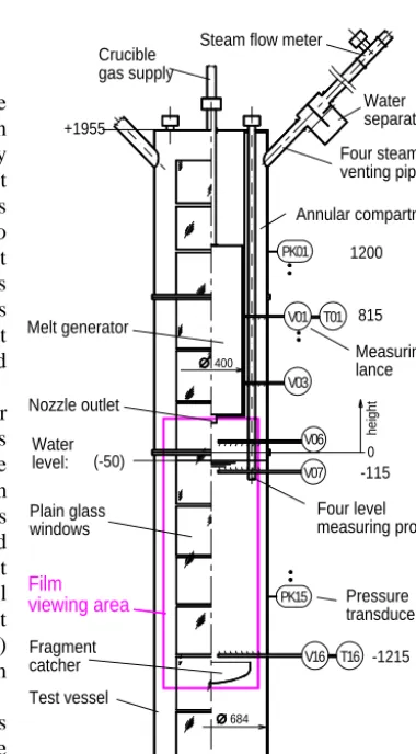
The test facility is shown in Figure 1. It consists of a slender cylinder with an effective inner diameter of 0.66 m bearing plane glass windows in the front and back sides. The upper part is occupied by the melt generator which leaves a 0.14 m wide annular space for the steam flow. The facility is entirely closed except for four large venting pipes (4 m long, each with a cross section of 90 cm2) which were also closed in two tests. The space below the melt generator is about 2.2 m high but for the processes to be studied, the actual height of the test water pool was determined by a concave debris catcher that could be mounted at different heights. The test rig was placed inside a large (220 m3) pressure vessel providing a safety barrier and the possibility to perform tests at elevated ambient pressure.
The tests were recorded visually by video and high-speed cameras and the pressures inside and outside the test vessel were measured. The initial increase of the water level was recorded by level meters. Furthermore, the water temperature and the distribution of water and
void within the test vessel were measured by thermocouples and local Fig. 1: PREMIX test facility
PK15 Fragment catcher Test vessel Film viewing area -2005 684 Pressure transducer
V16 T16 -1215
PK01
V01
V03
Steam flow meter
void probes, respectively. (Sometimes the destruction of a thermocouple indicated the arrival of melt.) In the open tests, the steam velocity in the vent pipes was measured. After the tests, the size distribution of the debris was determined.
The ideal test result would be the spatial distribution of the volume fractions of melt, liquid water and gas within the test vessel. But from the movies one can at least obtain the shape of the mixing zone as well as rough estimates of its volume and of mean volume fractions within it. The void probes give time resolved information about the volume fractions of water and steam at the locations in which they are installed (in arrays of 8 probes distributed radially). Besides that, pressures and steam flow rate give (indirect) evidence of heat transfer.
A total number of 18 experiments have been performed (see e.g. /25-28/). Details are given in Tables 1 and 2. After test PM11 the test rig had to be rebuilt since it was destroyed by a steam explosion (see chapter 2.3). It was slightly modified to have geometrical conditions as close as possible to FARO. In only one test (PM11) the single melt nozzle was replaced by three nozzles in a triangular array. All tests but PM17 and 18 were open to a constant pressure surrounding via the vent pipes. Duration of the melt release was typically 0.5...2.0 sec. In test PM16, with the largest melt mass, it was 6 sec. In this test, the outside pressure increased on the long run.
2.2 The course of typical experiments
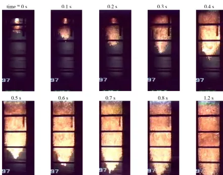
In test PM13 about 21 kg of melt have been released within 1.1 sec and with practically zero subcooling of the water. Movie pictures illustrating the melt penetration into the water pool are shown in Figure 2. As in all PREMIX tests, the melt initially penetrated into the water without detectable interaction (just film boiling). Only 0.32 sec after melt-coolant contact, when the melt had already penetrated 0.44 m into the water, the more intense thermal interaction typical of the premixing phase started. This led to the formation of a fairly regular shaped interaction zone which was highly voided and thus not translucent. There are also a few individual melt drops in the water around the interaction zone and in the gas space above it.
The onset of the more intense thermal interaction was also marked by a sudden pressure rise which continued in an oscillatory manner, see Figure 3. The pressure then approached a
Table 1: Parameters of the first PREMIX test series, PM1 – PM11
Exp MELT WATER m d ∆p ∆h
[kg] [mm] [MPa] [mm]
h T ∆T
[mm] [K] [K] PM1 PM2 PM3 PM4 PM5 PM6 PM7 PM8 PM9 PM10 PM11
9.3 45 0.078 198
9.4 45 0.085 163
9.2 45 0.085 180
9.1 45 0.075 185
9.0 45 0.08 200
20.2 60 0.092 198
9.6 40 0.39 145
10 45 0.08 0.0
21.8 60 0.095 0.0
27.3 60 0.09 0.0
≈20 3x35 0.07 0.0
1600 371 2
1600 373 0
1600 368 5
1600 368 5
1600 368 5
1600 371 2
1565 373 0
500 373 0 900 373 0 500 373 0 500 373 0 m = melt mass; in PM10 an exceptionally large mass of iron was found; d = nozzle diameter; ∆p = initial driving pressure difference measured; the initial speed of the melt released, estimated on basis of ∆p,
was about 6 m/s in most cases; ∆h = falling height; h = pool height; T = water temperature; ∆T = subcooling.
The melt temperature was ≈ 2600 K, the system pressure 0.1 MPa.
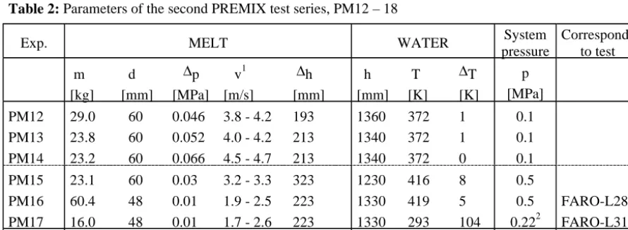
Table 2: Parameters of the second PREMIX test series, PM12 – 18
Exp. MELT WATER System
pressure
Corresponds to test
m d ∆p v1 ∆h [kg] [mm] [MPa] [m/s] [mm]
h T ∆T
[mm] [K] [K] p [MPa]
PM12
PM13 PM14
29.0 60 0.046 3.8 - 4.2 193
23.8 60 0.052 4.0 - 4.2 213 23.2 60 0.066 4.5 - 4.7 213
1360 372 1
1340 372 1 1340 372 0
0.1 0.1 0.1 PM15 PM16 PM17
23.1 60 0.03 3.2 - 3.3 323
60.4 48 0.01 1.9 - 2.5 223 16.0 48 0.01 1.7 - 2.6 223
1230 416 8
1330 419 5 1330 293 104
0.5
0.5 0.222
FARO-L28 FARO-L31
PM18 14.6 48 0.015 1.9 - 2.9 223 1330 365 30 0.222
1
constant level of about 0.16 MPa after about 1.3 sec. Slow gas flow started earlier, probably due to gas heating above the water and it rose quickly after 0.3 sec. It attained a practically constant value of 4.5 m3/sec after 0.65 sec, probably due to sonic choking in the droplet flow established after this time in the venting pipes. (As a rule one can state that soon after the start of the intense thermal interaction, the steam flow was strongly affected by entrained water masses.)
Figure 3 also displays a calculated pressure time curve. This was obtained after the test with the code MC3D 3.2 from CEA Grenoble as modified by FZK, employing three fields (melt, water and steam). The computational domain was limited by the test vessel and the outer boundary of the melt generator. An axisymmetric two-dimensional geometry was used with a mesh size of 2 cm in radial direction (with some smaller cells close to the axis where the melt penetrates into the water) and 5 cm in axial direction. The venting tubes were simulated by a pressure boundary condition assuming a pressure loss coefficient of 10 for the steam. No pressure losses were simulated for water and melt which are supposed to move in droplet flow. The inflow of melt at the melt generator nozzle was prescribed on the basis of experimental information. Except for a slight overestimation in the end, the simulation shows good agreement with the measured pressure. Also melt front velocity in the water and steam production are simulated satisfactorily. Other quantities like the losses of water and melt from the test vessel and the total melt surface are in the order of magnitude observed in the experiment.
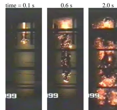
Figure 4 shows the mixing of melt and water in experiment PM17 which had 0.22 MPa system pressure and 104 K subcooling. The effect of these two parameters is clearly visible in the much reduced void volume that results in a much more narrow multiphase zone surrounding the melt jet. (Why some parts of the mixing zone appear to be obscured by black clouds in the water is not yet understood.)
The mass mean particle diameter of the debris found after the tests was typically about 10 mm.
Fig. 2: Progression of the interaction zone in PM13 shown by selected video film pictures.
time≈0 s 0.1 s 0.2 s 0.3 s 0.4 s
2.3 General conclusions from the whole test series
1. Melt jets can penetrate deeply into water pools without triggering an explosive event. Thus premixing is possible. This creates a multiphase zone. This zone is formed after a small delay of the order of 0.1...0.5 sec and its formation is accompanied by a steep pressure rise (by some tenths of a bar).
2. In none of the tests, the initial contact of the melt with the water surface caused a steaming excursion as has been observed in some medium-scale SANDIA tests /12/.
3. In none of the tests, the contact of melt with the pool bottom has triggered an explosive event as has often been observed in other experiments and is often quoted as a likely source of a trigger. This is even true of experiments in which a large molten mass has assembled on the pool bottom which was finally found as a 'cake' in the catch pan. 4. In only one of the experiments (PM11) an explosive event occurred. The pressure developed and consequently the
energetics of this event were low (pressure maximum estimated at 30 bar), probably because the test vessel had a design pressure of 6 bar only and disassembled quickly.
This explosion occurred in one of the two tests with only 0.5 m water depth, almost 1 sec after the first contact of the melt with the catch pan. At this time a large portion of the melt had settled in the catch pan while violent boiling (also off melt globules churning around) occurred in the water pool. The explosion appears to have been initiated by a larger coherent water mass contacting the melt pool (as evidenced by some void probes). Also the explosion centre was located directly above the catch pan as can be seen from the high-speed movies.
It is fairly certain that the melt release in three parallel jets, which is peculiar to this test, had no longer a relevant influence on the course of the experiment at the time of the explosion.
5. Melt release in three jets instead of one jet (PM11) occurred at a lower rate (increased flow resistance in the manifold). Nevertheless, pressure build-up occurred earlier (somewhat faster) than with one jet. This appears to be a natural consequence of the imposed prefragmentation of the melt.
6. Reproducibility of the mixing process is quite reasonable. It was tested in three consecutive experiments (PM12, 13, 14) in which the initial conditions were kept as constant as possible. The variations still observed can be attributed to remaining variations in the speed with which the melt was released.
7. With an increase of the melt velocity, the dwell time prior to the pressure increase decreases and the violence (pressure) of the boiling process increases somewhat, apparently because the size of the drops into which the jet breaks up decreases.
8. In the deep-pool (>1.3 m) experiments with a short melt delivery time (≤2 sec), most of the melt appears to have been fragmented into centimetre-sized droplets well above the bottom. Most of these have apparently been encrusted by a frozen surface in such a way that they did not form a coherent molten mass on the pool bottom (almost no 'cake' found afterwards).
In the shallow-pool (.5 m) experiments large molten masses have assembled on the pool bottom.
In the one experiment (PM16) at 5 bar ambient pressure and 6 sec melt delivery time, about 40 % of the mass have formed a 'cake' in the catch pan in spite of the deep water pool. It appears that in this case the larger drops remained essentially molten. In this test, only the smaller fragments solidified as such.
Fig. 3: Measured and calculated pressure in PM13 time (s)
pr
e
s
s
ur
e
(ba
r)
0.5 1 1.5 2
1 1.1 1.2 1.3 1.4 1.5 1.6 1.7 1.8
MC3D 3.2 Calculated PREMIX 13 Measured
time = 0.1 s 0.6 s 2.0 s
9. In the cases in which the melt jets have broken up completely above the pool bottom, this occurred at a water depth, L, of typically 1 m. Taking the nozzle diameter as jet diameter D, this leads to L/D values of 12...20. These agree roughly with those predicted by the Saito formula /29/.
10. Increased ambient pressure or water subcooling did not have a marked influence on the break-up length of the melt jet.
11. In the vented test vessels, the interaction pressure increased at least as long as melt entered the water pool. If steam flow was severely obstructed or even prevented, the pressure occasionally continued to rise for some fraction of a second.
12. As observed in one test with an extended melt delivery time (PM16), heat transfer rate and steaming rate remained, after the initial development, fairly constant as long as melt entered the water. This corresponds to the behaviour observed in FARO test L-28 using a UO2-based melt.
13. Typically about 20 % of the heat contained in the melt were transferred to the water during the first 9 sec.
14. Generally, the mixing process developed in a quasi-steady manner, i.e. the pressures in the water pool and in the gas space above, respectively, differed by the hydrostatic pressure only and, besides smaller oscillations, the pressure rose monotonically to a maximum at the end of the melt delivery time or shortly after that and then decreased monotonically over a long period.
In two cases a distinct local pressure excursion was observed at the pool bottom when the continuous melt jet reached the bottom. But they did not trigger explosive events. This agrees with the observation made in the SANDIA FITSB experiments /12/.
15. When the ambient pressure was increased while keeping the melt delivery conditions unchanged, the rate of heat transfer to the water and thus the rate at which steam mass was created remained almost the same. However, at the elevated pressure, the specific steam volume was smaller so that the multiphase zone around the jet became narrower. Also pressure rise and steam flow rate were reduced by about the pressure ratio.
That the smaller multiphase zone volume did not increase heat transfer may indicate that the melt surface created remained essentially unaffected and that heat transfer was primarily by radiation.
16. Both, increased ambient pressure and water subcooling, tended to reduce the width and thus the volume of the multiphase zone and the amount of level swell.
17. The volume fractions of water and steam in the multiphase zone around the melt jet could be determined during the initial period of melt penetration. With low subcooling, these volume fractions tended to become of similar size (around 45 %) within 0.3...0.4 sec. For subcooling up to 30 K, its effect remained within the uncertainties of the determination of the volume fractions which are especially large in the initial period when the total volumes were small.
At 100 K subcooling (PM17), the multiphase zone contained about 80 % of liquid water and about 10 % of melt and steam, respectively.
At 30 K subcooling (PM18) it was observed after the end of melt delivery, that a large number of incandescent particles entered the continuous water space surrounding the original (opaque) multiphase zone thus increasing the mass of melt that was mixed for sure with water. This means that essentially the whole water pool became the mixing zone. (The same is thought to have occurred with 100 K subcooling but could hardly be observed because the water itself became blackened in some areas in that experiment).
18. In the two experiments with high subcooling (PM17, 18), pressure oscillations with high frequencies were measured within the water pool. They are believed to result from subcooled boiling. There is evidence that these oscillations started when there was no longer a direct connection between the original multiphase zone and the gas space above the water.
3. THE ECO EXPERIMENT
3.1 Purpose and test conditions
The ECO experiments have been launched in 2000 to actually measure energy conversion in confined steam explosions under well defined conditions. The design of the facility is such that only work done on quite resistant surroundings by lasting pressure is measured. The kinetic energy of water that may be thrown upwards within the test volume is not registered. It is of no relevance in the accident case.
Again the alumina discussed above is used to simulate the core melt. The internal dimensions of the test facility as well as major test conditions are similar to PREMIX. Until now, two partly exploratory tests have been performed and will be described here. Their initial conditions are detailed in Table 3.
inside the test volume and force measurements in the support columns, respectively, and on measurements of the piston displacement which are performed by displacement transducers and by the visual observation of the facility by video and high-speed cameras. The third measurement is provided by the crushing material. It only gives the total amount of work.
Table 3: ECO-01 and ECO-02 test conditions
ECO-01 ECO-02
Melt
mass released kg temperature K
5.76
≈2600
2.87
≈2600 Melt release
driving pressure difference MPa nozzle diameter m height of fall m max. speed m/s
0.22-0.04-0.171 0.045 0.275 7.4 0.09 0.06 0.325 5.9 Water
temperature K pool depth m
293 1.10
293 1.05 System pressure MPa
Trigger pressure MPa
0.1-0.31 12
0.1 -2 1
varies during mixing 2
self-triggered steam explosion.
Fig. 5: Test facility in ECO-01,schematically P01
Strain gauge
" Cylinder "
Supporting column Water pool
Vessel = " Piston "
Crushing material Explosion trigger V08 P16 590 Displacement measurement 'L' Nozzle tube Melt generator case Crucible
0 100 200
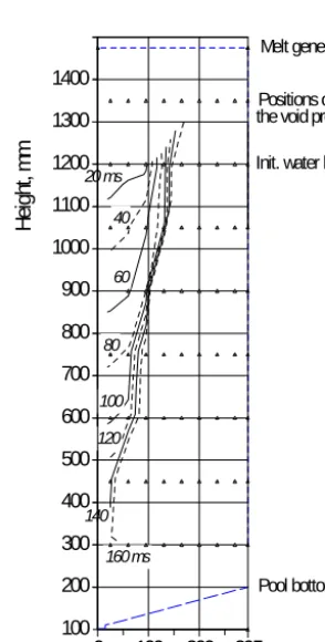
Radius, mm 100 200 300 400 500 600 700 800 900 1000 1100 1200 1300 1400 He igh t, m m 40 40 20 ms 60 60 80 80 100 100 120 120 140 160 ms 160 ms Pool bottom Positions of
Init. water level the void probes
295
Melt generator
The conditions within the melt-water mixing zone are observed by thermocouples and arrays of void probes like in PREMIX. Here they are especially important as no visual observation is possible.
The melt is released from the melt generator which is fixed to the stationary cylinder after melt-through of a steel foil as in PREMIX. However, in order that no water enters the melt generator, the exit nozzle is equipped with a fast acting slide valve that is closed prior to triggering the explosion or when the pressure in the test volume exceeds a preset limit. To make sure that a steam explosion is obtained in every experiment, a small explosive device is installed at the test vessel bottom for triggering the explosion. It is fired when two out of three selected void probes near the vessel bottom indicate void, i.e. the presence of melt, when the pressure exceeds a preset limit, or after a preset time delay after the onset of melt release.
As the experiments have just begun and data analysis including numerical simulations with MC3D are still ongoing, the data reported here are still preliminary.
3.2 ECO-01: Description and results
For ECO-01 the calculation of the velocity of melt release gives a maximum value of 8 m/sec at the onset. Figure 6 shows the development of the multiphase zone around the melt jet as a function of time (zero time is the onset of melt release as detected by a devoted thermocouple). During the mixing process, the pressure in the (closed) test vessel rose by about 0.23 MPa. This together with the strong initial subcooling explains the narrow multiphase zone which had the intended low void fraction. However, the melt velocity in the water was so high (around 7 m/sec) that only 5.76 kg of melt had left the melt generator when melt was detected close to the bottom, the melt generator was closed, and the trigger fired (at 0.169 sec).
Some representative pressure traces are shown in Figure 7 (note that the axial heights are not equally spaced). In higher resolution, the trigger peak can be identified in the trace of PK01 with a width of 0.1 msec and a height of almost 4.5 MPa. One can derive that this pulse moves upwards at a speed of about 1000 m/sec, apparently essentially in the single-phase water surrounding the mixing zone. But no strong, coherent or clearly propagating, steam explosion was
0.168 0.17 0.172 0.174 0.176 0.178 0.18 Time, s 0
5 10 15
Pr
essure
, M
Pa
PK01 / 0.3 m PK01 / 0.3 m PK04 / 0.6 m PK04 / 0.6 m PK06 / 0.9 m PK06 / 0.9 m
PK05 / 0.75 m PK05 / 0.75 m PK08 / 1.2 m PK08 / 1.2 m
PK_ECO_SMI
Fig. 7: Pressure data obtained at different levels in the water pool
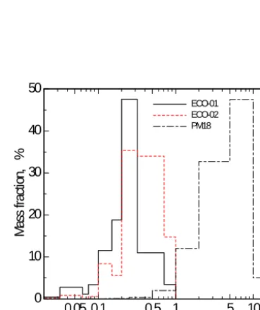
0.05 0.1 0.5 1 5 10
Particle size, mm 0
10 20 30 40 50
M
as
s fr
acti
on
,
%
ECO-01 ECO-01 ECO-02 ECO-02 PM18 PM18
triggered. The explosion rather seems to be composed of several quite localized events at different elevations. The explosion was essentially terminated after 8 msec.
After the test, most of the debris was found in the size range 0.20...0.32 mm, cf. Figure 8. This debris size is normally taken as indicating a steam explosion. (By contrast, see the much larger debris found in PREMIX test PM18 that is also shown in Figure 8.) Still energy conversion has been extremely small. The piston moved by 2 mm at best. This gives a work of W = 5.6 kJ. Compared to the total thermal energy, Q, of 24.2 MJ, a conversion factor η = Q/W = 0.02 % is obtained - a quite negligible result. We think that this is due to the large amount of cold water present which led to fast condensation of the steam.
3.3 ECO-02: Description and Results
The main idea for ECO-02 was to get more melt into the test vessel. Therefore the nozzle diameter was increased to 60 mm and the water level was slightly decreased. The plate closing the cylinder was provided with two venting holes in order to keep the pressure nearly constant during the premixing phase. Of course, these holes were equipped with fast sliding valves to close them prior to triggering the explosion or when the pressure rose before that.
In the test, actually a spontaneous interaction occurred after 0.211 sec when the melt had penetrated into the water almost 0.4 m. The total melt mass released prior to closing the melt generator nozzle was 2.78 kg. Nevertheless, the explosion appears to have been more violent than in ECO-01. The thermal interaction started close to the free surface at about 1.0 m height and propagated downwards. (The pool bottom is at 0.1 m.). The maximum pressures amounted to 20 MPa. They were measured at the levels of 0.6 m and 0.75 m. This spike was about 1 msec wide. It was reflected at the bottom reaching 32 MPa (and destroyed the trigger device). It then propagated upwards again, gradually dying out to about 10 MPa. This whole process took 2 msec. The event was finished before it could be influenced by the fact that the test vessel was still open (closing the relief paths takes about 10 msec). Only small amounts of melt and water were ejected.
As compared to ECO-01, the range of the debris size is extended towards somewhat larger values, 0.2...0.71 mm, see Figure 8. The work done in this experiment is similar to that of ECO-01. So the energy conversion factor is about twice as high - still negligible.
4. CONCLUSIONS
Steam explosions might be a threat to reactor plant structures during a hypothetical core melt accident in water cooled reactors. Numerical analysis tools are being developed to analyze such events with much more realism than hitherto possible and to reduce unnecessary conservatisms. In order to improve the understanding of the phenomena involved and to provide reliable and relevant data for code testing, improvement and validation, two types of experiments are performed at Forschungszentrum Karlsruhe: The PREMIX experiment studying the premixing phase and the ECO experiment investigating the explosion proper. In both these experiments, the molten core material is simulated by a very hot (2600 K) oxidic melt that consists mainly of alumina.
A total of 18 PREMIX experiments have been performed. Besides a large data base for code verification they have delivered insights into the influence of parameters like ambient pressure, melt jet velocity and water subcooling on the character of the premixing process as well as the occurrence and effectiveness of spontaneous triggers. Properties of the premixing zone have been obtained in much detail.
The ECO experiment serves to measure pressure and energy conversion in steam explosions that are externally triggered and contained in a cylinder-and-piston system in order to really measure the mechanical energy release. Two experiments have been performed until now. They gave extremely low energy conversion, probably because the melt/water mass ratio was too small and steam condensation was very rapid.
REFERENCES:
1. Cronenberg, A. W. and Benz, R., “Vapor explosion phenomena with respect to nuclear reactor safety assessment, in: Lewins, J. and Becker, M. (Eds.)”, Advances in Nuclear Science and Technology, Vol. 12, pp. 247-338 (1980) 2. Reid, R.C., “Rapid Phase Transitions from Liquid to Vapor”, Adv. Chem. Eng. 12, pp. 105-208 (1983),
3. Corradini, M. L., “Vapor explosions: A review of experiments for accident analysis”, Nuclear Safety 32 (1991) 337-62
4. Berthoud, G., “Vapor Explosions”, Annu. Rev. Fluid Mech. 2000, pp. 573-611
6. Struwe, D., Jacobs, H., Imke, U., Krieg, R., Hering, W., Böttcher, M., Lummer, M., Malmberg, T., Messemer, G., Schmuck, Ph., Göller, B., and Vorberg, G., “Consequence Evaluation of In-Vessel Fuel Coolant Interactions in the European Pressurized Water Reactor”, Forschungszentrum Karlsruhe Report, FZKA 6316, July 1999
7. Board, S.J. and Hall, R.W., “Recent Advances in Understanding Large-Scale Vapor Explosions”, The 3rd Specialist Meeting on Sodium-Fuel Interactions, Tokyo, PNC N251, 76-12, pp. 249-283 (1976)
8. Cline, D. D., Pong, L. T., Beck, D. F. and Berman, M., “An equation of state formulation for Hicks-Menzies FCI efficiencies”, in: S. B Yilmaz (Ed.): Heat Transfer – Philadelphia, 1989, AiChE Symp. Series # 269, Vol 85, 1989, 48-53
9. Chen, X., Yuen, W. W., Theofanous, T. G., “On the constitutive description of the Microinteractions concept in steam explosions”, Nucl. Eng. Des. 177 (1997) 303-19
10. Spencer, B. W., Wang, K., Blomquist, C. A., McUmber, L. M. and Schneider, J. P., “Fragmentation and Quench Behavior of Corium Melt Streams in Water”, ANL Report NUREG/CR-6133, ANL-93/32 (1994)
11. Bird, M. J., “An experimental study of scaling in core melt/water interactions”, 22nd Natl Heat Transfer Conf., Niagara Falls, NY, August 1984
12. Mitchell, D. E., Evans, N. A., “Steam Explosion Experiments at Intermediate Scale: FITSB Series”, SNL report NUREG/CR-3983, SAND83-1057 (February 1986)
13. Berman, M. (Ed.), “Light Water Reactor Safety Research Program Quarterly Progress Report, January-March 1981”, SNL Report NUREG/CR-2163/1 of 4, SAND81-1216/1 of 4 (July 1981)
14. Farawila, Y. M. and Abdel-Khalik, S. I., “On the Calculation of Steam Explosion Conversion Ratios from Experimental Data”, Nucl. Sci. Eng. 104 (1990) 288-295
15. Berman, M. (Ed.), “Light Water Reactor Safety Research Program Semiannual Report”, October 1983 - March 1984, SNL Report NUREG/CR-4459, SAND85-2500 (February 1986)
16. Tarbell, W. W. and Pilch, M., “Pressurized Melt Ejection Into Water Pools”, SNL Report NUREG/CR-3916, SAND84-1531, March 1991
17. Maruyama, Y., Yamano, N., Kudo, T., Hodaka, A. and Sugimoto, J., “Accident management measures on steam explosion and debris coolability for light water reactors”, CSNI Spec. Meeting on Selected Containment Severe Accident Management Strategies, Stockholm, S, June 13-15, 1994
18. Park, H. S., Chapman, R., Corradini, M. L., “Vapor Explosions in a One-Dimensional Large-Scale Geometry with Simulant Melts”, University of Wisconsin, Report NUREG/CR-6623 (1999)
19. Huhtiniemi, I. and Magallon, D., “Insight into steam explosions with corium melts in KROTOS”, Nucl. Eng. Des. 204 (2001) 391-400
20. Magallon, D. and Huhtiniemi, I., “Corium melt quenching tests at low pressure and subcooled water in FARO”, Nucl. Eng. Des. 204 (2001) 369-76
21. Marshall, B. W., Beck, D. F. and Berman, M., “Mixing of isothermal and boiling molten-core jets with water: the initial conditions for energetic FCIs”, Proc. Int. ENS/ANS Conf. on thermal reactor safety, Avignon, F, 2-7 October 1988, pp.117-27
22. Angelini, S., Theofanous, T. G. and Yuen, W. W., “On the regimes of premixing”, Nucl Engn Des 189 (1999) 139-62
23. Duplat, F., Berthoud, G. and Hamon, M., “Recent results on the BILLEAU premixing experiment using cold and hot spheres (2200 K) and comparisons with MC3D calculations”, Proc. 1997 Intl Mtg on Advanced Reactor Safety, Orlando, FL, 1-5 June 1997, pp. 529-37
24. Meyer, L., Schumacher, G., Jacobs, H., and Thurnay, K., “Investigation of the premixing phase of a steam explosion with hot spheres”, Nuclear Technology 123 (1998) 142-55
25. Schütz, W., Huber, F., Kaiser, A., Will, H., ”PREMIX, an experimental approach to investigate the mixing behaviour of a hot melt being poured into water”, Proc. 1997 Int. Meeting on Advanced Reactor Safety, Orlando/Florida, June 1-5, 1997, Vol. 1, pp. 887-894
26. Magallon, D., Huhtiniemi, I., Dietrich, P., Berthoud, G., Valette, M., Schütz, W., Jacobs, H., Kolev, N., Graziosi, G., Sehgal, R., Bürger, M., Buck, M., von Berg, E., Colombo, G., Turland, B., Dobson, G., Monhardt, D., “Molten fuel coolant interaction (MFCI)”, FISA 99, EU Research in Reactor Safety Luxembourg, 29.11. to 1.12.1999, EUR 19532 EN (2000)
27. Magallon, D., Huhtiniemi, I., Dietrich, P., Berthoud, G., Valette, M., Schütz, W., Jacobs, H., Kolev, N., Graziosi, G., Sehgal, R., Bürger, M., Buck, M., von Berg, E., Colombo, G., Turland, B., Dobson, G., Monhardt, D., “Characterisation of Molten-Fuel Coolant Interaction Processes (MFCI)”, FINAL REPORT, EUR 19567 EN (2000) 28. Kaiser, A., Schütz, W., Will, H., ”PREMIX Experiments PM12-PM18 to Investigate the Mixing of a Hot Melt
being Poured into Water”, FZK Scientific Report FZKA-6380 (2001)