ABSTRACT
BARILOVITS, STEPHEN. Experimental Study of a Unique Multi-Row Meltblowing Fiber Formation Process and the Web Structures Produced Thereby. (Under the direction of Drs. Saad A. Khan and Eunkyoung Shim.)
Nano- and micro-polymeric fibers find widespread use in our lives in the form of engineered fabrics that require high surface areas and/or small pore sizes. These fabrics are used in high efficiency filtration, medical apparel, thermal and acoustic insulation. Meltblowing technology is a preferred method of producing such fibers, having been well studied and solidly established in the industry. A multi-row variant of the traditional process has also been commercialized, offering a higher maximum throughput and potentially producing stronger fibers with a wider range of polymer resins. Despite the commercial availability and possible advantages of multi-row meltblowing, it has not yet been publically studied in detail. In an effort to provide a better and more consolidated understanding of this process and its capabilities, this research was conducted to experimentally examine the fiber formation process and explain how it creates fibers and web structures.
Fiber diameters depended predominantly on polymer throughput and air temperature, with higher air speeds reducing diameters only at high polymer throughputs. Median diameters from the various processing conditions ranged from 0.76 to 13.8 µm. Infrared thermography demonstrated that significant heat transfer occurs between the polymer and the air immediately prior to spinning. Air temperature and velocity profiles were measured in the absence of spinning fibers to estimate the environment around the fibers during spinning. An empirical model was developed to predict median fiber diameter using the knowledge of thermal and physical conditions within the first centimeter of fiber spinning. Agreement of this model with the measured fiber diameters demonstrates that total fiber diameter attenuation is largely determined by conditions of the polymer jet very close to the spinnerets.
Careful examination of the polymer jets using ultra-speed videography and high-resolution photography revealed, for some conditions, a pulsation of the polymer jet, causing it to swell and retract periodically with frequencies of about 1 – 4 Hz. The pulsation exhibits different behavior from “draw resonance” and is observed to allow both large and small fibers to be formed from a single spinneret. Adjusting processing conditions to produce smaller fibers results in more severe pulsation, causing jet breakage and shot formation as the median fiber diameter drops below 1.0 µm. The jet pulsation increases the relative width of the diameter distributions and alters their shapes. Fiber diameters were distributed normally for larger median diameters to skewed-lognormal for small median diameters. The pulsation of the polymer jet certainly reduces median fiber diameters but may also limit diameter attenuation by causing shot formation.
however, clearly increase the incidence of spun fusion web defects and thereby increased effective fiber diameters even when individual diameters remained essentially unchanged.
Experimental Study of a Unique Multi-Row Meltblowing Fiber Formation Process and the Web Structures Produced Thereby
by
Stephen Barilovits
A dissertation submitted to the Graduate Faculty of North Carolina State University
in partial fulfillment of the requirements for the degree of
Doctor of Philosophy
Chemical Engineering
Raleigh, North Carolina 2018
APPROVED BY:
_______________________________ _______________________________
Dr. Eunkyoung Shim Dr. Saad A. Khan
Committee Co-Chair Committee Co-Chair
_______________________________ _______________________________
ii DEDICATION
iii BIOGRAPHY
iv ACKNOWLEDGEMENTS
One of the most rewarding parts of my experience as a graduate student has been the ability to collaborate with others, learn from them, and solve problems together. First and foremost, I thank Dr. Eunkyoung Shim for her guidance in navigating this journey, from solving the day-to-day problems that arise in experimentation, to guidance of the project overall. She is uniquely devoted to her students which explains her track record of success stories. I have been lucky to have her on my team. I thank Dr. Saad Khan threefold: first for his encouragement and efforts to usher me into the field of chemical engineering, second for his support and guidance on the research project, and third for his advice on my personal development. I thank Dr. Behnam Pourdeyhimi for his experienced feedback on this project and advice for the effective communication of the work.
Almost all of my experimental work involved Nonwovens Institute staff and technicians who provided invaluable assistance in the successful execution of experimental objectives. I extend my thanks to Bruce Anderson for all the imaging help in this highly imaging-intensive project, to Eric Lawrence and William Barnes for their help in numerous successful fiber-forming trials and experiments, to Amy Minton for help in material characterization, and to Abhay Joijode for his rheological help and spinneret-blocking advice.
v I thank the students in the Khan Research Group as well as the Nonwovens Institute. I especially thank Miika Niikinmaa for giving me many good and novel ideas on the project and effective presentation of results. I also thank Salvatore Luiso for working together with me on rheological calculations.
vi TABLE OF CONTENTS
LIST OF TABLES ... ix
LIST OF FIGURES ...x
Chapter 1 – Introduction and Background ...1
1.1 Nonwovens Background and Industry Future ... 1
1.2 Meltblowing for Fine Fiber Production ... 2
1.3 Multi-Row Meltblowing Using Annular Spinnerets ... 7
1.4 References ... 12
Chapter 2 - Experimental Investigation of the Fiber Formation Process and Web Structures using an Annular Meltblowing Spinneret ...14
2.1 Abstract ... 14
2.2 Introduction ... 15
2.3 Experimental ... 19
2.3.1 Material ... 19
2.3.2 Material Characterization ... 19
2.3.3 Dual-Row Meltblowing ... 20
2.3.4 Infrared Thermography of Spinning Fibers ... 24
2.3.5 Air Temperature and Velocity Profiling ... 25
2.4 Results and Discussion ... 26
2.4.1 Air Temperature and Velocity Profiles in the Fiber-Forming Region ... 26
2.4.2 Temperature of Spinning Fibers ... 31
2.4.3 Polymer Thermal and Rheological Characterization ... 37
2.4.4 Two-Row Meltblowing Fiber Diameter Distributions ... 39
2.4.5 DCD Effects on Fiber Size and Bonding Distance ... 42
2.5 Conclusions ... 45
2.6 References ... 48
vii
2.7.1 Tracking of Lateral Fiber Motions ... 50
2.7.2 Online Measurement of Fiber Bending Instabilities Using Back-Folding Distance ... 54
2.7.3 Bulk Fiber Speed ... 56
Chapter 3 - Meltblown Polymer Jet Pulsation: Observations and Effects on Fiber Diameter Distribution in an Annular Meltblowing Spinneret Design ...58
3.1 Abstract ... 58
3.2 Introduction ... 59
3.3 Experimental ... 63
3.3.1 Material ... 63
3.3.2 Dual-Row Meltblowing ... 63
3.3.3 Ultra-High-Speed Videography ... 67
3.3.4 High-Resolution Photography ... 68
3.3.5 Fiber Diameter Measurement ... 68
3.4 Results and Discussion ... 68
3.4.1 Fiber Diameter Distributions ... 68
3.4.2 Pulsation of the Polymer Jet ... 73
3.5 Conclusions: ... 84
3.6 References ... 86
Chapter 4 - High Throughput Multi-Row Meltblowing: Effects of Increasing Fiber-Forming Rows on Fiber Diameter Distributions and Web Defects ...91
4.1 Abstract ... 91
4.2 Introduction ... 91
4.3 Experimental ... 95
4.3.1 Material ... 95
4.3.2 Multirow Meltblowing ... 96
viii
4.3.4 Fiber Diameter Measurement ... 102
4.4 Results and Discussion ... 102
4.4.1 Air Temperature and Velocity Profile ... 102
4.4.2 Fiber Diameters and Distributions ... 107
4.4.3 Web Defect: Spun Fusion ... 113
4.5 Conclusions ... 119
4.6 References ... 120
4.7 Supplementary Information ... 122
4.7.1 Fiber Diameter Measurement Using a Semi-Automated Method ... 122
4.7.2 Processing Conditions and Fiber Diameter Distributions ... 124
ix LIST OF TABLES
Table 2.1 Process variables and their specific conditions ...24 Table 2.2 Air cavity conditions as they affect the air temperature and velocity 1.0 cm
in front of the fiber-forming spinnerets. ...31 Table 2.3 Back-folding distance (in centimeters) of fibers undergoing bending
instability during fiber formation. Distances for when the centerline air temperature drops to 120 °C, the crystallization temperature of PP, are shown for reference. * Indicates that fibers were so small that they were barely visible; determining back-folding events was very difficult for these
conditions. ... 55 Table 2.4 Bulk fiber speed at 8 cm from the spinnerets compared to air speed at the
same location, for all conditions ... 57 Table 3.1 Process variables and their specific conditions ... 67 Table 3.2 Fiber diameter distributions as defined by Shapiro-Wilk test results.
Subscripts of normal and lognormal indicate test result statistics from the fiber diameters and the logarithm of the diameters, respectively. All
distributions observed satisfy one and only of the shown criteria. ... 70 Table 3.3 Median fiber diameter, distribution type and distribution dispersity for
each 26 samples collected. Distributions indicated by * are shown as
histograms in Figure 3.3. ... 72 Table 3.4 Median fiber diameters, processing conditions, and jet pulsation
amplitude... 78 Table 4.1 Process variables and their specific conditions ... 100 Table 4.2 Processing condition by condition identifying number. Fabrics formed
from all condition for 2, 4, and 6 fiber spinning rows. ... 124 Table 4.3 Fiber diameter distribution dispersities for each condition and number of
x LIST OF FIGURES
Figure 1.1 Traditional Meltblowing Equipment [14]. (a) The meltblowing process;
(b) Fiber-forming die. ... 5 Figure 1.2 Multi-Row Meltblowing Die [29]. (a) Cross sectional view; (b) Die face
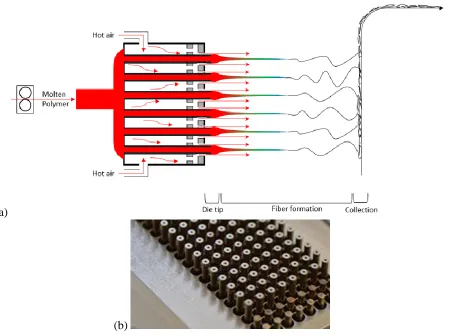
view. ... 8 Figure 2.1 (a) Side schematic representation of the multi-row meltblowing design
and fiber formation process. (b) Photo of an eight-polymer-row die face, with two air-only outlets at the die edge. (Photo courtesy of Biax
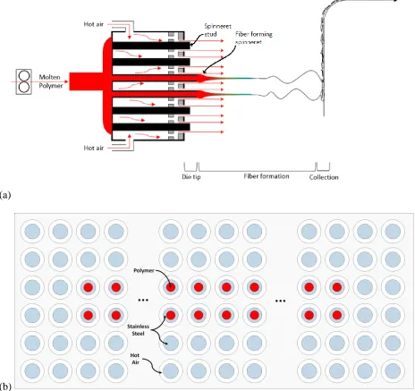
Fiberfilm Corp) ... 17 Figure 2.2 (a) Schematic side view of the 2-row meltblowing process; (b)
Schematic front view of the die face showing red polymer extrusion from the fiber forming spinnerets, blue hash steel spinneret wall and studs, and white hot air releasing annuli; (c) Relevant dimensions of the spinnerets (not shown: spinnerets extend 3.0 mm past the air annuli
face, and spinneret studs extend 1.5 mm past the same face). ... 21 Figure 2.3 Side schematic view of the locations where air temperature and
velocities were measured. ... 25 Figure 2.4 Air temperature and velocity measurements for various positions in
front of the die face for the single processing condition where air cavity temperature and pressure were 240 °C, and 97 kPa, respectively. Red star ( ) location measurements are shown for other processing conditions in Table 2.2. (a) Air temperature profile. (b) Air velocity profile. (c) Air temperature and velocity within the air stream measured
1.0 cm in front of the spinnerets. ... 27 Figure 2.5 (a) Side view IR photographs of spinning fibers; air velocity was 56 m/s
and polymer throughput 0.17 grams/hole/minute for both images shown. (b) Air temperature and speed effect on relative fiber temperature as a function of distance from the spinnerets (polymer throughput was 0.10 gram/hole/minute). (c) Air temperature and poylmer throughput effect on relative fiber temperature as a function of distance from the
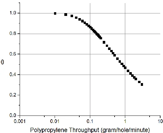
spinnerets. ... 33 Figure 2.6 Temperature equilibration fraction as a function of polypropylene
throughput for a spinneret length of 2.5 cm. θ = TPP − TiTw − Ti, where Tpp is the fiber spinning temperature, Ti is the polymer melt
temperature, and Tw is the air cavity temperature. ... 36
Figure 2.7 Rheological characterization of LyondellBasell MF 650W
xi low shear limit with exponential extrapolation A exp(-BT), where A =
7.60 x 10⁶ Pa∙s and B = 2.59 x 10⁻² °K-1 ... 38 Figure 2.8 Fiber diameter distributions for each air speed, air temperature, and
polymer throughput level listed in Table 2.1. DCD was 40 cm for all conditions. Samples marked with * toward the right of the figure indicate the presence of any amount of shot. Shot and fly for the rightmost condition prevented the sample from being collected and
analyzed. ... 40 Figure 2.9 DCD effect on fiber diameter ... 43 Figure 2.10 Determining bonding distance by SEM inspection. Processing
conditions: throughput = 0.17 gram/hole/minute, air temperature = 240 °C, air speed = 56 m/s. (a) Heavily bonded. (b) Highest DCD exhibiting bonding: portions of fibers crossing at high angles are visibly bonded. (c) DCD greater than bonding distance: fibers crossing at high angles
that clearly touch are not visibly bonded. ... 44 Figure 2.11 Fiber bonding distances compared to distance for the centerline air
temperature to reach 120 °C. ... 46 Figure 2.12 Fiber lateral motion for air temperature of 166 °C, air speed of 46 m/s,
and polymer throughput of 0.17 gram/hole/minute. (a) A fiber tracked over 20 ms at 3 and 6 cm from the spinneret outlet. (b) A fiber tracked
over 20 ms at 9 and 11.2 cm from the spinneret outlet. ... 52 Figure 2.13 Amplitude of fiber lateral motion oscillations for various distances from
the spinneret outlet. ... 53 Figure 2.14 Schematic representation of back-folding distance. ... 55 Figure 3.1 (a) Side schematic representation of the multi-row meltblowing design
and fiber formation process. (b) Photo of an eight polymer row die face, with two air-only outlets at the die edge. (Photo courtesy of Biax
Fiberfilm Corp) ... 61 Figure 3.2 (a) Schematic side view of the 2-row meltblowing process; (b)
Schematic front view of the die face showing red polymer extrusion from the fiber forming spinnerets, blue hash steel spinneret wall and studs, and white hot air releasing annuli; (c) Relevant dimensions of the spinnerets (not shown: spinnerets extend 3.0 mm past the air annuli face
and spinneret studs extend 1.5 mm past the same face). ... 63 Figure 3.3 Representative fiber diameter distributions as histograms with 1 µm bin
xii Figure 3.4 Fiber diameter distributions by number and by mass fraction,
histograms with 1 µm bin size. Data sets were taken from Figures 3.3(a), (d), and (e), respectively for (a), (b), and (c). Dispersity: D =
σ/Dmed. ... 73
Figure 3.5 In the region of fiber bending instabilities, a large fiber is clearly visible along with many smaller fibers that are difficult to discern given the
image resolution. ... 74 Figure 3.6 Top-down view of spinnerets from an ultra-high speed cine showing a
sharp increase of polymer released from one spinneret into a larger fiber. Five spinneret columns are visible in this field of view, and the release of polymer from a second spinneret is visible in the rightmost image. The median fiber diameter collected from this condition was
0.76 µm. ... 75 Figure 3.7 High resolution photos of the polymer jet issuing from a single
spinneret at different moments during the jet pulsation. ... 76 Figure 3.8 Shot particle; median diameter of fibers was 0.76 µm. ... 79 Figure 3.9 Polymer jet diameter profile with time, for three polymer flow rates. Air
temperature was 240 °C, air speed was 56 m/s. ... 80 Figure 3.10 Polymer jet pulsation as caused by the annular spinneret aerodynamic
configuration. ... 81 Figure 3.11 Jet pulsation period for high amplitude conditions. ... 82 Figure 3.12 Fiber diameters from large (2-row) capillaries and from small (4-row)
capillaries. For all diameters shown, air temperature was 166 °C, polymer throughput was 0.05 gram/hole/minute, and DCD was 40 cm (a) Air speed 56 m/s. (b) Air speed 68
m/s.………. 89 Figure 4.1 Annular meltlblowing spinneret. ... 94 Figure 4.2 (a) Schematic side view of the multirow meltblowing process for six,
four, and two fiber forming rows; (b) Schematic front view of the 6-row die face showing red polymer extrusion from the fiber forming
spinnerets, blue hash steel spinneret wall and studs, and white hot air releasing annuli; (c) Relevant dimensions of the spinnerets (not shown: spinnerets extend 3.0 mm past the air annuli face and spinneret studs
extend 1.5 mm past the same face). ... 97 Figure 4.3 Side schematic view of the locations where temperature and velocity
xiii Figure 4.4 Air temperature and velocity measured across the air stream 1 cm in
front of spinnerets. Spinnerets were “dry”, i.e. no fibers were formed during the measurement. Measurement type by numeral: I. Air Temperatures; II. Air Speeds. Air cavity conditions by letter: (a) 48.3 kPa, 182 °C; (b) 48.3 kPa, 240 °C; (c) 68.9 kPa, 182 °C; (d) 68.9 kPa,
240 °C. ... 104 Figure 4.5 Fiber diameter for different number of spinning rows relative to the
average for all rows, for various processing conditions. ... 108 Figure 4.6 Cumulative fiber diameter distributions from all conditions where DCD
= 40 cm, for two, four, and six fiber spinning rows. Each distribution
results from approximately 3000 fiber diameters measured. ... 110 Figure 4.7 Fiber diameter distribution dispersity for all conditions (where DCD =
40 cm), spun from 2, 4, and 6 spinneret rows. ... 112 Figure 4.8 Fiber fusion counting procedure: a line is draw approximately
perpendicular to the machine direction of the fiber orientation. Individual and fused fibers are counted that cross this line. This procedure applied to this image gives 43 fibers total (fused or
individual), 22 fibers involved in 10 fusions. 22/43 or 51% of fibers are
fused. ... 114 Figure 4.9 Effect of processing conditions on the incidence of fiber fusion. (a) Air
temperature effects (for DCD = 40 cm, averaged across row number, air velocity, and polymer throughput); (b) Air velocity effects (for DCD = 40 cm, averaged across row number, air temperature, and polymer throughput); (c) Polymer throughput effects (for DCD = 40 cm,
averaged across row number, air temperature and air velocity); (d) DCD
effects (averaged across all conditions and row number). ... 115 Figure 4.10 Fiber fusion rates for all processing conditions (where DCD = 40 cm)
for fibers spun from 2, 4 and 6 fiber forming spinneret rows. ... 117 Figure 4.11 Fiber diameter distributions as determined manually (using ImageJ
software) shown in red, and using a semi-automated program
(AutoFiber from Mann+Hummel Group) shown in blue. Kolmogorov-Smirnov two sample test p-values shown. Processing conditions: (a) air temperature of 166 °C, air speed of 55 m/s, polymer throughput of 0.10 ghm, DCD of 15 cm; (b) air temperature of 166 °C, air speed of 55 m/s, polymer throughput of 0.10 ghm, DCD of 20 cm; (c) air temperature of 166 °C, air speed of 55 m/s, polymer throughput of 0.10 ghm, DCD of 30 cm; (d) air temperature of 166 °C, air speed of 55 m/s, polymer
throughput of 0.10 ghm, DCD of 40 cm. ... 123 Figure 4.12 Fiber diameter distributions as cumulative distributions for all samples
2-xiv row case, red from the 4-row case, and green from the 6-row case.
Table 4.2 displays processing conditions for each condition number. Kolmogorov-Smirnov two sample test p-values shown: P_2/6 shows the p-value results when 2 and 6-row distributions are compared,
1 1 Chapter 1 – Introduction and Background
1.1 Nonwovens Background and Industry Future
While nonwoven textiles trace their origin to ancient or even prehistoric wool feltmaking [1], as a cohesive industry the field is less than a century old. A need to convert fibrous material not suitable for yarn marking into useful products, along with other considerations, led to the development of revolutionary technologies capable of producing textile-like fibrous products without weaving or knitting operations [2]. While the origins of the modern industry cannot be pinpointed, critical ideation leading to the modern industry certainly include needle looming equipment from the 1870s, adhesive bonding techniques from the 1920s, and integrated spun-laid processes from the 1950s-1970s. Nonwoven production technologies encompass numerous subsidiary technologies, most of which have become industries in their own right. While this thesis concerns only a spun-laid process, more specifically a particular meltblowing process, the reader not familiar with the nonwovens industry is encouraged to consult textbook references on the field [2], [3]. Only to put the research into context, a cursory overview of nonwovens and their applications is given here.
2 therefore necessarily lower performance alternatives to traditional textiles. Indeed, nonwovens often have cost and/or production speed advantages over traditional textiles, as well as advantages in the diversity of possible structures and materials with which to make them.
The future of the global nonwovens industry arguably lies in increasing production capacity to serve developing markets and the incorporation of novel materials to create new products or existing products with more desirable properties. The nonwovens market is more mature in western Europe and North America than it is in the rest of the world. A growing middle class in some of the world’s most populous countries drives increasing consumption of nonwoven-containing goods in those areas. Higher production capacity and cost reduction will therefore continue to be priorities of the industry for the foreseeable future. However, the expected increase in nonwoven consumption, especially disposables, also fuels environmental concerns related to sustainability and biodegradation. The future of the nonwoven industry in its established markets may even depend on its ability to meet regulatory demands by replacing fossil-fuel-based polyolefins with sustainably sourced and/or biodegradable components [5]. Thus, efforts are currently being made to develop novel materials and to modify processes to economically produce nonwoven products from these new materials.
1.2 Meltblowing for Fine Fiber Production
3 diameter, so small fiber diameters yield high surface area fabrics. Pore size is a more complex function of fabric properties but is directly proportional to fiber diameter [6], so small fiber diameters also reduce fabric pore sizes. The finest natural fibers used commonly in textiles such a silk, fine wools and cottons typically have diameters larger than 10 µm. Synthetic polymeric fiber production methods such as monocomponent spunbonding and melt spinning also rarely produce fibers less than 10 µm in diameter.
5 (a)
(b)
Figure 1.1 Traditional Meltblowing Equipment [14]. (a) The meltblowing process; (b) Fiber-forming die.
6 The term polymer jet is used to describe the molten polymer in the region close to the capillary outlet where rapid axial acceleration dominates the dynamics of fiber formation. As the polymer jet speed approaches the air speed and the jet becomes quite narrow, it is typically referred to as a fiber from this point on. This fine fiber has a low bending rigidity, allowing it to undergo complex bending motions that further reduce cross sectional diameters [16]. Fibers also may crystalize before, during, or after they are collected. The distance over which fibers traverse, termed the Die-Collector Distance (DCD), dictates in large part the extent to which fibers will crystalize in the air prior to collection. For sufficiently short DCDs, fibers do not fully crystalize before collection and have a tacky surface, allowing the fibers to bond to one another immediately upon collection. Such autogenous bonding is a unique capability of the meltblowing process, allowing for the production of stiff, heavily bonded fabrics or flexible, lightly bonded ones based on DCD variations alone [2].
7 density, and hydrophobicity, which prevents the need to pre-dry the polymer pellets before meltblowing.
The process and equipment described above are commonly used and well-studied, but variants to the traditional meltblowing process have also been patented and commercialized. For example, the air outlets have been modified to create supersonic air jets [21], the effects of which have been studied [22]. Additionally, several machinery variations have been made to enable meltblowing of multi-component fibers [23]–[25]. Significant deviations from the traditional design can allow for the production of hollow fibers in a meltblowing process [26], [27]. While these variations can create structures that the traditional die design cannot, they retain the fundamental limitations of meltblowing: weak fibers and a limited choice of highly compatible polymers.
1.3 Multi-Row Meltblowing Using Annular Spinnerets
8 (a)
(b)
9 Referring to the numbered labels of Figure 1.2, the design requires capillaries (#3) to traverse an air cavity (#5), putting the polymer and air into thermal contact prior to fiber spinning. Not shown in Figure 1.2(a), the polymer distribution (#2) is typically achieved using a series of modular distribution plates to distribute polymer from the extrusion pipe evenly to each capillary. The capillaries, also known as spinnerets, extend several millimeters past the air annuli outlets (#19) to allow the air stream to become directed parallel to the spinnerets and assist in isolating the polymer jets from one another. Capillaries flush with the air annuli outlets, or recessed behind them, as is sometimes the case for slot dies [10], can cause polymer jets to collide with one another during spinning [29]. Also not shown in Figure 1.2, spinnerets may be blocked from emitting polymer. Many commercial dies contain “air curtain” rows, perimeter spinnerets whose capillaries are blocked from spinning fibers but still release air. The objective of air curtain rows is to insulate the interior polymer jets from cool entraining room air, reducing fiber diameter and diameter distributions.
10 Equipment manufacturers also claim that fibers produced using the annular meltblowing design are stronger and can be made from a wider variety of polymers than traditional meltblowing. The process has been termed “Spun-blown®” to emphasize that fibers made with the process have fiber sizes similar to meltblowing, but strength intermediate between weak traditional meltblown fibers and stronger spunbonded fibers [30]. Lower extrusion pressures can allow the use of polymers of higher viscosity (and lower MFRs). Even if little crystalline orientation develops, the ability to operate with higher viscosity and higher molecular weight polymers can alone produce stronger structures [20]. The ability to change polymer temperature immediately prior to fiber spinning can minimize thermal degradation of polymers, also creating stronger fibers.
Although the fiber formation process for traditional meltblowing, and many variants to that die configuration, have been studied extensively, the multi-row annular spinneret design has not yet been studied openly and systematically. It is known that the aerodynamics close to the spinnerets are of critical importance to the fiber formation process in the traditional design [32], so it cannot be assumed that the findings from slot-die meltblowing studies can be applied to this altered design. The design has the potential to produce strong, fine fibers at high throughput and with a variety of polymers and may therefore play an important role in the production of high-performance nonwovens for years to come. A better understanding of the process advantages and limitations is needed for appropriate application of the technology. The goal of this work is to provide the first thorough understanding of this fiber and web formation process.
12 1.4 References
[1] B. Gordon, Feltmaking. Watson-Guptill Publications, New York, 1980. [2] S. Batra and B. Pourdeyhimi, Introduction to Nonwovens Technology. 2012.
[3] S. J. Russell, Handbook of nonwovens. Woodheaed Publishing Limited and CRC Press LLC, Boca Raton, FL, 2007.
[4] “INDA Annual Report,” 2014.
[5] A. Koukoulas, “Nonwovens and the Sustainability Inperative,” in RISE 2017, 2017. [6] K. Matsumoto, T. Yunoki, and K. Nakamura, “Effect of fiber diameter, porosity and
basis weight on pore size and pore size distribution of stainless steel non-woven fiber filter,” KAGAKU KOGAKU RONBUNSHU, vol. 30, no. 1, pp. 79–86, 2004.
[7] R. Groten, J. Baravian, and G. Riboulet, “United States Patent ( 19 ),” 5970583, 1999. [8] A. Durany, N. Anantharamaiah, and B. Pourdeyhimi, “High surface area nonwovens via
fibrillating spunbonded nonwovens comprising Islands-in-the-Sea bicomponent filaments: Structure-process-property relationships,” J. Mater. Sci., vol. 44, no. 21, pp. 5926–5934, 2009.
[9] X. Wang and Q. Ke, “Experimental Investigation of Adhesive Meltblown Web Production Using Accessory Air,” Polym. Eng. Sci., vol. 46, no. 1, pp. 1–7, 2006. [10] C. J. Ellison, A. Phatak, D. W. Giles, C. W. Macosko, and F. S. Bates, “Melt blown
nanofibers : Fiber diameter distributions and onset of fiber breakup,” Polymer (Guildf)., vol. 48, pp. 3306–3316, 2007.
[11] M. E. S., G. M. Glenn, A. P. Klamczynski, W. J. Ortis, and L. H. C. Mattoso, “Solution Blow Spinning: A New Method to Produce Micro- and Nanofibers from Polymer Solutions,” J. Appl. Polym. Sci., vol. 113, no. 4, pp. 2322–2330, 2009.
[12] D. H. Reneker and I. Chun, “Nanometre diameter fibres of polymer, produced by electrospinning,” Nanotechnology, vol. 7, pp. 216–223, 1996.
[13] V. Wente, “Superfine Thermoplastic Fibers,” Ind. Eng. Chem. Res., pp. 342–346, 1955. [14] J. P. Keller and R. R. Buntin, “Melt-Blowing Die For Producing Nonwoven Mats,”
3825380, 1974.
[15] R. Butin, J. P. Keller, and J. Harding, “Non-Woven Mats by Melt Blowing,” 3849241, 1974.
[16] A. L. Yarin, S. Sinha-ray, and B. Pourdeyhimi, “Meltblowing : II-linear and nonlinear waves on viscoelastic polymer jets,” J. Appl. Phys., vol. 108, 2010.
13 [18] B. R. R. Bresee and W. Ko, “Fiber Formation During Melt Blowing,” Int. Nonwovens J.,
2003.
[19] S. Fischer, O. Marti, T. Diesner, and B. Rieger, “Small-Angle X-ray Scattering on Melt-Spun Polypropylene Fibers : Modeling and Data Reduction,” Macromolecules, vol. 43, pp. 5009–5015, 2010.
[20] J. Schultz, Polymer Chrstalization: The Development of Crystalline Order in Thermoplastic Polymers. Oxford University Press, New York, 2001.
[21] A. S. . Fabbricante, G. F. Ward, and T. J. Fabbrincante, “Micro-Denier Nonwoven Materials Made Using Modular Die Units,” 6,114,017, 2000.
[22] D. H. Tan, P. K. Herman, A. Janakiraman, F. S. Bates, S. Kumar, and C. W. Macosko, “Influence of Laval nozzles on the air flow field in melt blowing apparatus,” Chem. Eng. Sci., vol. 80, pp. 342–348, 2012.
[23] V. Bansal, M. Davis, and E. Rudisill, “APPARATUS FOR MAKING
MULTICOMPONENT MELTBLOWN FIBERS AND WEBS,” 7008207, 2006. [24] M. A. Allen, “METHOD FOR MELTBLOWING MULTI- COMPONENT LIQUID
FILAMENTS,” 6946093, 2005.
[25] B. Haynes and M. C. Cook, “DIE FOR PRODUCING MELTBLOWN
MULTICOMPONENT FIBERS AND MELTBLOWN NONWOVEN FABRICS,” 7150616, 2006.
[26] L. B. Torobin, “Method and Apparatus for Producing Microfilaments,” 4363646, 1982. [27] C. Torobin, L., Finlow, “Method and Apparatus for Producing High Efficiency Fibrous
Media Incorporating Discontinuous Sub-Micron Diameter Fibers, and Web Media Formed Thereby,” 6183670, 2001.
[28] E. C. A. Schwarz, “Apparatus and Process of Melt-Blowing A Fiberforming Thermoplastic Polymer and Product Produced Thereby,” 4380570, 1983.
[29] E. Schwarz, “Apparatus and Process for Uniformly Melt-Blowing A Fiberforming Thermoplastic Polymer in a Spinnerette Assembly of Multiple Rows of Spinning Orifices,” 5476616, 1995.
[30] Biax Fiberfilm, “Spun-blown Meltblown Systems,” 2015. [Online]. Available: http://www.biax-fiberfilm.com/spunblownmeltblown/.
[31] G. F. Ward, “Meltblown nanofibres for nonwoven filtration applications,” Filtr. Sep., vol. 38, no. 9, pp. 42–43, 2001.
14 2 Chapter 2 - Experimental Investigation of the Fiber Formation Process and Web
Structures using an Annular Meltblowing Spinneret
Stephen Barilovits, Eunkyoung Shim, Saad A. Khan, Behnam Pourdeyhimi
Department of Chemical and Biomolecular Engineering and the Nonwovens Institute, North Carolina State University, Raleigh, NC (USA).
This chapter is under revision for publication.
2.1 Abstract
15 2.2 Introduction
A nonwoven fabric is a fibrous sheet or web structure that is held together not by intricate knitting or stitching operations but by much faster mechanical, thermal, or chemical means [1]. Nonwovens find use in a wide range of applications, from medical gowns, wipes, and diaper liners, to geotextiles, carpeting, and apparel interlinings. Industry worldwide sales were nearly $36 billion in 2014. Many important nonwoven applications such as filtration, barrier fabric, and insulation require high surface and/or small pore sizes, both of which require small fiber diameters. Technologies have therefore been developed to produce ever smaller fibers. Electrospinning technology produces the industry’s most narrow fiber diameters, often less than 100 nm, but requires solvents and is orders of magnitude slower than other techniques [2].
16 Meltblowing technology has advanced from proof-of-concept experiments in the 1950s to a highly productive and versatile commercial system. Exxon first commercialized the process in the 1970s using what has become the industry standard linear meltblowing die [6]. In this setup, molten polymer is pushed through a single row of capillary outlets and attenuated into fibers by converging air curtains. This design has been studied experimentally and theoretically, and has been modified to create supersonic air streams and multicomponent fibers [7]–[11]. Departures from the standard linear die have also been patented and commercialized, but not as thoroughly studied [12]–[14].
17 (a)
(b)
Figure 2.1 Multi-row meltblowing process. (a) Side schematic representation of the multi-row meltblowing design and fiber formation process. (b) Photo of an eight-polymer-row die face, with two air-only outlets at the die edge. (Photo courtesy of Biax Fiberfilm Corp)
19 2.3 Experimental
2.3.1 Material
All experiments used LyondellBasell MF 650W Isotactic Polypropylene, a commercial meltblowing grade homopolymer resin. The manufacturer states that polymerization was metallocene catalyzed, so the molecular weight distribution is expected to be low. The stated melt flow rate at 230 °C and a 2.16 kg mass was 500 g/10 min using ASTM D1238, and the density at 23 °C was 0.90 g/cm3 using ASTM D792.
2.3.2 Material Characterization
Polymer thermal properties were measured in duplicate using a TA Instruments first-generation Discover Series Differential Scanning Calorimeter (DSC) and Thermogravimetric Analyzer (TGA). TGA and DSC heating experiments were conducted at 5 °K per minute, and DSC cooling was performed at 10 °K per minute. Steady shear and dynamic oscillatory flow behavior of the molten polymer was characterized using a 25 mm diameter parallel plate TA Instruments Discovery Hybrid Rheometer HR-3. Dynamic oscillatory rheology was measured from 0.1 rad/s to 600 rad/s and related to steady shear viscosity using the Cox-Mertz relationship [20].Steady shear viscosity was measured at shear rates from about 800 s-1 to about 7500 s-1 using an Instron
CAEST SR20 Capillary Rheometer. Capillary measurements were adjusted for end effects and wall slip using the Bagley and Rabinowitz corrections, respectively [21], [22]. Steady shear viscosity versus shear rate from 0.1 s-1 to about 7500 s-1 is presented for several temperatures in
20 2.3.3 Dual-Row Meltblowing
A pilot-scale two-row meltblowing die was selected to study the unique annular spinneret design. The equipment and die used, termed the Spunblown® process, was manufactured by Biax-Fiberfilm Corporation [14], [23]. The die was 38 cm in width, contained two fiber spinning rows with a total of 368 spinnerets. The adjacent fiber-forming spinneret rows were surrounded on all sides by two air-only (non-fiber-forming) rows, which serve to insulate the spinning fibers from cool air entrainment. The total number of air annuli, both those surrounding the fiber-forming spinnerets and spinneret studs, was 1128. The inner diameter of the fiber-forming spinnerets was 508 µm. Schematic representations of the specific die and system are displayed in Figure 2.2.
22 (a)
(b)
24 In the multi-row meltblowing die design, molten polymer is pushed through a series of distribution plates and into 2.5 cm long cylindrical spinnerets. The spinnerets traverse an air cavity (see Figure 2.2a) and emit the polymer several millimeters in front of the die face. Hot air flows into the air cavity and escapes through the annuli surrounding the spinnerets and spinneret studs. In these experiments, four process variables were investigated: air cavity temperature, air cavity pressure, polymer flow rate, and DCD. Their conditions spanned the range of typical safe use of the equipment and polymer and are shown in Table 2.1. DCD was not varied in the full factorial manner and was set to 40 cm for most conditions. Other important process parameters were held nearly constant: melt tesmperature was about 240 °C, die temperature was 220 °C, collector speed was 3.05 m/min, and collector suction was set to 40% of machine maximum.
Table 2.1 Process variables and their specific conditions
Process Variable Conditions
Air Cavity Temperature (°C) 166, 182, 240 Air Cavity Pressure (kPa) 48.3, 68.9, 97.2 Polymer Throughput (gram/hole/minute) 0.050, 0.100, 0.170
Die-Collector Distance (cm) 15.0, 20.0, 25.0, 30.0, 35.0, 40.0
2.3.4 Infrared Thermography of Spinning Fibers
25 2.3.5 Air Temperature and Velocity Profiling
The air temperature and velocity profiles in front of the spinnerets were measured using a K-type thermocouple and FlowKinetics FKT 2DP1A-C device with a 7.94 mm diameter pitot tube attachment, respectively. Absolute velocity measurements require simultaneous air temperature measurement, which was accomplished by mounting the thermocouple about two centimeters away from the pitot tube in the positive x-direction (see Figure 2.3), so as not to disturb the air flow near the pitot tube. Both devices were mounted on a robotically controlled stage (Benchtop PRO 2424 from CNC Router Parts) to take measurements at locations of a repeatable accuracy of ±0.02 mm for a 3D array of positions. The locations of the measured sites are shown in Figure 2.3, and measurements were performed for each of the nine air cavity temperature and pressure conditions shown in Table 2.1.
Figure 2.3 Side schematic view of the locations where air temperature and velocities were measured.
26 20 seconds, and the values reported here were averaged over the last 8 seconds of that hold time. This procedure allowed the probes to equilibrate to the new environment of each position. 2.4 Results and Discussion
2.4.1 Air Temperature and Velocity Profiles in the Fiber-Forming Region
28 (a)
(b)
30 Figure 2.4(a) and Figure 2.4(b) show centerline and above centerline air conditions. The air profile was assumed to be symmetric about the centerline, which was verified at 10 and 20 cm from the die face. Figure 2.4 shows that the air heat dissipates more rapidly than does the air momentum; this is especially noticeable close to the spinneret as seen in Figure 2.4(c). In that figure, air heat dissipation is clear because the temperature profile is parabolic in shape, while the air speed profile is essentially flat. Heat and momentum dissipation trends are also seen for off-centerline air temperature values in Figure 2.4(a), which approach off-centerline values more rapidly than the off-centerline air speed values approach centerline values in Figure 2.4(b). Fiber-forming spinnerets are located at ±1 mm along the Y-coordinate, close enough to the center that the air surrounding the fibers 1 cm past the spinnerets is still approximately 220 °C. Figure 2.4(c) shows the dramatic effect of the non-fiber-forming spinneret stud rows that emit only air (located at ±3 and ±5 mm) and serve to effectively insulate the fibers at the center from cooler room air. If the spinneret studs were converted to fiber-forming rows, those fibers would be exposed to cooler air much earlier in the fiber-forming process. The cooler air would cool the polymer jet, reducing its extensibility and presumably resulting in thick fibers formed at the perimeter of the die and fine fibers formed at the center. In essence, the particular die configuration studied here has been designed to minimize fiber diameter distribution caused by the cool air entrainment effect.
31 Table 2.2 Air cavity conditions as they affect the air temperature and velocity 1.0 cm in front of the fiber-forming spinnerets.
Air Cavity Pressure Effects Air Cavity Temperature Effects Air Cavity Pressure
(kPa)
Air Velocity at 1.0 cm (m/s)
Air Cavity Temperature (°C)
Air Temperature at 1.0 cm (°C)
48.3 46 166 168
68.9 56 182 183
97.2 68 240 235
Changes in air cavity pressures and temperatures did not appreciably affect the air temperatures or velocities, respectively, just in front of the spinnerets. Air temperature just in front of the spinnerets deviates from air cavity values likely due to heat transfer with the die, which was attempted to be held constant at 220 °C. The air velocity values shown in Table 2.2 are used below to develop an empirical model for the effect of air speed on median fiber diameter.
2.4.2 Temperature of Spinning Fibers
34 (a)
(b)
35 As can be seen from Figure 2.5, the fiber spinning temperature is a strong function of air temperature, even though the melt temperature entering the spinnerets was hardly changed between the conditions. Higher air speeds universally resulted in faster initial cooling rates of the fibers than did lower air speeds. Higher polymer throughputs made for slower initial cooling rates. Taking these observations together, we conclude that finer fibers cool more quickly than do larger fibers. Also, when air temperature was 182 °C or 166 °C, higher polymer throughput increased the maximum fiber temperatures observed. Melt temperature entering the spinnerets was held constant at 240 °C, so this dependence results from changes in residence time of the polymer inside the spinneret.
Absolute fiber spinning temperature is determined analytically rather than by measurement. This calculation is simplified by neglecting the radial temperature gradient and assuming a plug flow profile inside the capillaries. The result from performing the energy balances, the temperature of the polymer in Kelvin (TPP) as a function of axial distance, x, is
𝑇𝑝𝑝(𝑥) = 𝑇𝑤 + (T𝑖 − Tw)e−𝛽x (1)
where 𝛽 = 2ℎ
𝜌𝐶𝑝𝑣𝑥𝑅; 𝑎𝑛𝑑 ℎ = 𝑁𝑢
𝑘
2𝑅. Tw is the air temperature inside the air cavity, Ti is the process “melt temperature”, the temperature of the polymer as it enters the capillary, Nu is the Nusselt number for plug flow in the thermal entrance region of a pipe with constant wall temperature [25], k is the thermal conductivity of polypropylene [26], Cp is the constant pressure heat capacity of
polypropylene [26], vx is the axial velocity of the polymer, R is the radius of the capillary, and ρ
is the melt density of polypropylene. The capillaries are approximately 2.5 cm long, so
36 This relationship can be used to make a useful plot showing the heat transfer as a function of the polymer throughput, in a plot similar to that shown in the process original patent [14]. Letting 𝜃 =𝑇𝑃𝑃−𝑇𝑖
𝑇𝑤−𝑇𝑖, which represents the fraction of temperature equilibration achieved in the
spinnerets prior to spinning, and solving this quantity for different throughputs produces Figure 2.6.
Figure 2.6 Temperature equilibration fraction as a function of polypropylene throughput for a spinneret length of 2.5 cm. 𝛉 =𝐓𝐏𝐏−𝐓𝐢
𝐓𝐰−𝐓𝐢, where Tpp is the fiber spinning temperature, Ti is the polymer melt temperature, and Tw is the air cavity temperature.
Figure 2.6 can be used to predict the fiber spinning temperature of polypropylene for the annular meltblowing spinneret configuration for any of the available capillary geometries (provided the length of the capillary is 2.5 cm, the capillary length for most commercially available dies). In accordance with Figure 2.6, the IR-determined relative fiber spinning temperature in Figure 2.5(c) shows that higher polymer throughput increases the fiber spinning temperature for
37 temperature difference, as is predicted. These calculations therefore validate the air temperature and polymer throughput effects on fiber spinning temperature seen experimentally in Figure 2.5. 2.4.3 Polymer Thermal and Rheological Characterization
To provide a processing temperature range for this polypropylene resin (LyondellBasell MF 650W), DSC and TGA experiments were performed to give the lower and upper bounds, respectively. The thermal profiles show that this resin must be heated to at least 170 °C to ensure complete melting, but not above about 250 °C to prevent thermal degradation. DSC also shows that crystallization of the quiescent melt of this polymer does not begin until it is cooled to about 120 °C, indicating that fiber spinning is possible in the range of 120 to 250 °C.
38
(a)
(b)
39 Figure 2.7 shows that the viscosity of this polymer can be adjusted between 10 and 80 Pa∙s within the temperature operating limits given from DSC and TGA. The temperature dependence of the zero-shear viscosity gives a useful indication of the relative extensibility of the polymer melt, and in the following section, with the knowledge of the fiber spinning temperature discussed above, it is used to model the dependence of the fiber diameter on the air temperature.
2.4.4 Two-Row Meltblowing Fiber Diameter Distributions
40 Figure 2.8 Fiber diameter distributions for each air speed, air temperature, and polymer throughput level listed in Table 2.1. DCD was 40 cm for all conditions. Samples marked with * toward the right of the figure indicate the presence of any amount of shot. Shot and fly for the rightmost condition prevented the sample from being collected and analyzed.
41 flow ratio and the air to (zero shear) polymer viscosity ratio. The mass flow ratio takes into account polymer throughput and air speed effects, while the viscosity ratio takes into account air temperature effects. Among numerous forms available, the form
𝑑 = 𝐶1+ 𝐶2𝑀𝑎𝜂𝑏 (2)
showed the best fit to the data. M represents the air to polymer mass flow ratio, d the modeled fiber diameter in micrometers, and η the air to polymer dynamic viscosity ratio, with C1,
C2, a, and b constants to be chosen. The air mass flow was calculated using the centerline air
velocity one centimeter in front of the spinnerets (shown in Table 2.2) through the cross sectional area of the rectangle that encloses the air annuli that surround the fiber-forming spinnerets (373.25 x 3.42 mm). Thus the effect of the air-only rows is ignored in this empirical model. Air viscosity as a function of temperature was found via reference [28]. Polymer viscosities were found by first calculating the temperature of the polymer at the spinneret tip using equation (1), then finding the viscosity of the polymer at that temperature using the exponential extrapolation shown in Figure 2.7. The values C1 = 0.0100 µm, C2 = 0.05247 µm, a = -1.48, and b = -0.768 produced the modeled
points shown in Figure 2.8; the R2 value for this regression with respect to the median fiber
diameters was 0.97.
42 conditions of greater axial acceleration of the polymer jet near the spinneret (see supplementary information for fiber bending instabilities).
This model also shows the relative importance of air temperature, speed, polymer throughput, and polymer viscosity in causing fiber diameter reduction for this spinneret design. The fact that the exponent a is nearly twice the magnitude of b shows that polymer throughput and air velocity has a greater effect on fiber diameter than does polymer viscosity. It is, however, the value of b that is of greater importance in practice. This is because achieving fine fibers though polymer viscosity modification by appropriate resin selection can be more economical than by increasing heated air volumes and/or reducing polymer throughput. Commercial meltblowing operations typically seek to produce fibers quickly, as measured in kilograms per meter of die per hour, and a reduction in total polymer throughput is moving in the wrong direction economically. Also, the primary cost associated with the meltblowing process is the energy required to heat the large volumes of air [16]. Therefore, it is costly to reduce fiber diameters by increasing air speed and temperature. This empirical model can be used as the basis for resin and condition selection as well as to analyze the tradeoffs involved for producing fibers of a desired diameter.
2.4.5 DCD Effects on Fiber Size and Bonding Distance
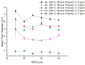
43 Figure 2.9 DCD effect on fiber diameter
The effect of DCD on fiber diameter was largely insignificant for 20 cm and beyond, and at 15 cm all samples showed substantial bonding between fibers. Fiber bonding refers to fibers contacting the collecting belt while still partially molten and sticking together. This indicates that reducing the DCD will not increase the fiber diameter without also causing significant fiber bonding. This also provides further understanding of the fiber formation process, in that fibers continue to attenuate, albeit modestly, even farther from the die up to the point that they crystalize.
44 by noting the highest DCD, in 5 cm increments, in which fibers could be seen in the SEM images with some molten part bonding high angle crossing fibers together; see Figure 2.10.
(a) (b) (c)
Figure 2.10 Determining bonding distance by SEM inspection. Processing conditions: throughput = 0.17 gram/hole/minute, air temperature = 240 °C, air speed = 56 m/s. (a) Heavily bonded. (b) Highest DCD exhibiting bonding: portions of fibers crossing at high angles are visibly bonded. (c) DCD greater than bonding distance: fibers crossing at high angles that clearly touch are not visibly bonded.
45 2.5 Conclusions
This experimental work serves as a basis for understanding the fiber and web formation process of the annular variant of the meltblowing process. Thermal exposure of the polymer melt to the attenuating air stream prior to fiber spinning is a unique aspect of the annular meltblowing design. The air-polymer heat transfer allows for rapid alteration of the melt temperature immediately before spinning. The impact of air temperature on fiber diameters is explained by the effect of temperature-dependent viscosity of the polymer melt. Experimental variations in air temperature, air speed, polymer throughput, and DCD spanned a wide range of conditions to test the limits and capabilities of the process. Webs were collected containing fibers with median diameters from submicron to more than 10 µm. Shot formation occurred when median fiber diameters were less than 1.2 µm. Investigation of the effects of processing conditions on fiber diameters show that fiber diameters can be accurately predicted by knowledge of the air profile and polymer properties associated with the first centimeter of fiber spinning.
46 Figure 2.11 Fiber bonding distances compared to distance for the centerline air temperature to reach 120 °C.
48 2.6 References
[1] INDA, “INDA | About Nonwovens http://www.inda.org/about-nonwovens/,” 2017. [Online]. Available: http://www.inda.org/about-nonwovens/.
[2] D. H. Reneker and I. Chun, “Nanometre diameter fibres of polymer, produced by electrospinning,” Nanotechnology, vol. 7, pp. 216–223, 1996.
[3] A. L. Yarin, S. Sinha-ray, and B. Pourdeyhimi, “Meltblowing : II-linear and nonlinear waves on viscoelastic polymer jets,” J. Appl. Phys., vol. 108, 2010.
[4] S. Batra and B. Pourdeyhimi, Introduction to Nonwovens Technology. 2012.
[5] C. J. Ellison, A. Phatak, D. W. Giles, C. W. Macosko, and F. S. Bates, “Melt blown nanofibers : Fiber diameter distributions and onset of fiber breakup,” Polymer (Guildf)., vol. 48, pp. 3306–3316, 2007.
[6] J. P. Keller and R. R. Buntin, “Melt-Blowing Die For Producing Nonwoven Mats,” 3825380, 1974.
[7] A. L. Yarin, S. Sinha-ray, and B. Pourdeyhimi, “Meltblowing : Multiple polymer jets and fi ber-size distribution and lay-down patterns,” Polymer (Guildf)., vol. 52, no. 13, pp. 2929–2938, 2011.
[8] M. Uyttendaele and R. L. Shambaugh, “Melt Blowing : General Equation Development and Experimental Verification,” AICHE J., vol. 36, no. 2, pp. 175–186, 1990.
[9] D. H. Tan, C. Zhou, C. J. Ellison, S. Kumar, C. W. Macosko, and F. S. Bates, “Meltblown fibers: Influence of viscosity and elasticity on diameter distribution,” J. Nonnewton. Fluid Mech., vol. 165, no. 15–16, pp. 892–900, 2010.
[10] B. Haynes and M. C. Cook, “Die for Producing Meltblown Multicomponent Fibers and Meltblown Nonwoven Fabrics,” 7150616, 2006.
[11] A. S. . Fabbricante, G. F. Ward, and T. J. Fabbrincante, “Micro-Denier Nonwoven Materials Made Using Modular Die Units,” 6,114,017, 2000.
[12] V. T. Marla, R. L. Shambaugh, and D. V Papavassiliou, “Using Swirl Dies To Spin Solid and Hollow Fibers,” Ind. Eng. Chem. Res., vol. 45, pp. 2331–2340, 2006.
[13] C. Torobin, L., Finlow, “Method and Apparatus for Producing High Efficiency Fibrous Media Incorporating Discontinuous Sub-Micron Diameter Fibers, and Web Media Formed Thereby,” 6183670, 2001.
[14] E. C. A. Schwarz, “Apparatus and Process of Melt-Blowing A Fiberforming Thermoplastic Polymer and Product Produced Thereby,” 4380570, 1983.
[15] V. Wente, “Superfine Thermoplastic Fibers,” Ind. Eng. Chem. Res., pp. 342–346, 1955. [16] B. Haynes, “An experimental and analytical investigation on the production of microfibers
49 [17] A. Begenir, S. Michielsen, and B. Pourdeyhimi, “Melt-Blowing Thermoplastic Polyurethane and Polyether-Block-Amide Elastomers : Effect of Processing Conditions and Crystallization on Web Properties,” Polym. Eng. Sci., vol. 49, pp. 1340–1349, 2009. [18] H. M. Laun, H. Schuch, H. M. Laun, and H. Schuch, “Transient Elongational Viscosities
and Drawability of Polymer Melts * Republic of Germany,” J. Rheol. (N. Y. N. Y)., vol. 119, no. 1989, 1994.
[19] V. T. Marla, R. L. Shambaugh, and D. V Papavassiliou, “Online Measurement of Fiber Diameter and Temperature in the Melt-Spinning and Melt-Blowing Processes,” Ind. Eng. Chem. Res., vol. 48, no. 18, pp. 8736–8744, 2009.
[20] W. P. Cox and E. H. Merz, “Correlation of Dynamic and Steady Flow Viscosities,” J. Polym. Sci., vol. 28, no. 118, pp. 619–622, 1958.
[21] E. B. Bagley, “End corrections in the capillary flow of polyethylene,” J. Appl. Phys., vol. 28, no. 5, pp. 624–627, 1957.
[22] B. Rabinowitsch, “Zeitschrift für physikalische Chemie,” Zeitschrift für Phys. Chemie, vol. 145, no. 1, pp. 1–26, 1929.
[23] E. Schwarz, “Apparatus and Process for Uniformly Melt-Blowing A Fiberforming Thermoplastic Polymer in a Spinnerette Assembly of Multiple Rows of Spinning Orifices,” 5476616, 1995.
[24] V. T. Marla, R. L. Shambaugh, and D. V Papavassiliou, “Use of an Infrared Camera for Accurate Determination of the Temperature of Polymer Filaments,” Ind. Eng. Chem. Res., vol. 46, pp. 336–344, 2007.
[25] W. J. Beek and R. Eggink, De Ingenieur. 1962.
[26] J. E. Mark, Ed., Physical Properties of Polymers Handbook, 2nd ed. Springer New York, 2006.
[27] R. L. Shambaugh, “A Macroscopic View of the Melt-Blowing Process for Producing Microfibers,” Ind. Eng. Chem. Res., vol. 27, pp. 2363–2372, 1988.
50 2.7 Supplementary Information
2.7.1 Tracking of Lateral Fiber Motions
To understand the extent to which fiber bending or flapping motions can contribute to fiber diameter reduction, researchers have utilized high-speed videography to directly monitor these motions with time [29], [30]. Each of these studies monitored fibers formed using a single-orifice homemade slot-die device, with polymer flow rates of 1 gram per minute or higher. For this study, a Phantom v1612 Ultrahigh-Speed Camera was used visualize and track the rapid motions of the spinning fibers studied here. The camera was equipped with a Canon 180 mm Macro lens whose face was positioned 18 cm from the fibers at the center of the die, giving a minimum spatial resolution of about 80 µm. Two plasma light sources (Hive Lighting, Killer Maxi Par Kit) capable of delivering 500,000 lux of continuous light was used to illuminate fibers directly, and as a backlight source. Video recordings were made for 1-2 second intervals for each of the 27 conditions varying air cavity temperature and pressure, and polymer throughput. Each condition was recorded at two video resolution and frame speed combinations: 128x800 (1 cm x 6.4 cm) at 58,252 frames/second, and 128x128 (1 cm x 1 cm) at 310,000 frames/second.
51 taken to ensure the same fiber is being tracked at all times, especially after two or more fibers overlap in the image.
52 (a)
(b)
53 While the movements are not sinusoidal, if the amplitude is described as the difference between opposite maximal excursions from the mean, then the amplitude of fiber lateral movements increases as the fiber moves away from the spinnerets. Figure 2.12(b) shows the fiber leaving the field of view at 0.002 and 0.014 s. The increase of amplitude from these images is shown in Figure 2.13.
Figure 2.13 Amplitude of fiber lateral motion oscillations for various distances from the spinneret outlet.
54 than twice the speed of the motions to be measured [31]. This means that to monitor the fast motions of meltblown fiber vibrations with time requires ultra-high-speed videography. Camera speeds prior to this work were not sufficiently fast enough to observe these motions if they occurred at all, given the different polymer flow rates and aerodynamic configurations studied.
While Figure 2.12 must be created using direct manual fiber tracking, it is not necessary to track intermediate positions to create a plot like Figure 2.13. Provided the fibers are large enough to discern at all, amplitudes can be more quickly determined from individual fiber observation and the recording of extreme points only. This has not been done systematically for the other conditions, but qualitatively, amplitudes of fiber motions for conditions spinning smaller fibers than the condition shown in Figure 2.12 and Figure 2.13 appear to be larger at shorter distances from the spinneret.
2.7.2 Online Measurement of Fiber Bending Instabilities Using Back-Folding Distance
55 Figure 2.14 Schematic representation of back-folding distance.
Back-folding distances for each processing condition where DCD was 40 cm were measured and are shown in Table 2.3.
Table 2.3 Back-folding distance (in centimeters) of fibers undergoing bending instability during fiber formation. Distances for when the centerline air temperature drops to 120 °C, the crystallization temperature of PP, are shown for reference. * Indicates that fibers were so small that they were barely visible; determining back-folding events was very difficult for these conditions. Air Temperature (°C) Polymer Throughput (ghm)
Air Speed (m/s)
46 56 68
165 (Air T = 120
°C at 7 cm)
0.17 >11.2 11.2 10.7
0.10 11 8.5 8.4
0.05 8.2 7 6.8
182 (Air T = 120
°C at 8 cm)
0.17 10.7 9.9 9.2
0.10 10.2 8.8 6.1
0.05 5.3* 5.1* 4.3*
240 (Air T = 120 °C at 12 cm)
0.17 6 5.5 4.8
0.10 4.4 4.2 4.1
0.05 2.9* 2.9* 2.9*
56 higher air speeds, and lower polymer throughputs result in more rapid fiber acceleration. In contrast to fibers that undergo back-folding at higher distances, fibers that back-fold earlier have accelerated more quickly and to a higher velocity and will undergo complex bending motions in a warmer environment and for a longer time before reaching the collection belt. Fine and warmer fibers have a lower bending rigidity than cooler and thicker fibers [3], allowing them to more completely follow the turbulent eddies of the air stream, further reducing their diameter. In this way, an additional fiber diameter reduction mechanism can play an increasing role in fiber diameter reduction when the initial axial acceleration is higher. This gives further indication that the conditions affecting the fiber formation very close to the spinneret largely determine the final fiber diameters resulting from all attenuating mechanisms.
2.7.3 Bulk Fiber Speed
57 Table 2.4 Bulk fiber speed at 8 cm from the spinnerets compared to air speed at the same location, for all conditions
Number Air Temp (°C) Air Speed (m/s) Throughput (ghm)
Bulk Fiber Speed at 8 cm from die
(m/s)
Air Speed at 8 cm from die
(m/s)
1 166 56 0.1 42.8 ± 2.4 40.9
2 166 68 0.1 47.1 ± 2.9 49.2
3 166 46 0.1 32.1 ± 1.4 34.1
4 166 56 0.05 36.0 ± 2.4 40.9
5 166 68 0.05 49.6 ± 2.0 49.2
6 166 46 0.05 30.3 ± 1.3 34.1
7 166 56 0.17 40.7 ± 1.0 40.9
8 166 68 0.17 49.3 ± 2.3 49.2
9 166 46 0.17 35.6 ± 1.0 34.1
10 182 56 0.1 40.7 ± 1.4 41.8
11 182 68 0.1 45.7 ± 1.0 48.7
12 182 46 0.1 32.2 ± 1.0 33.8
13 182 56 0.05 38.4 ± 1.6 41.8
14 182 68 0.05 46.6 ± 1.9 48.7
15 182 46 0.05 27.5 ± 0.6 33.8
16 182 56 0.17 40.3 ± 0.8 41.8
17 182 68 0.17 46.1 ± 1.4 48.7
18 182 46 0.17 32.4 ± 0.9 33.8
19 240 56 0.1 42.7 ± 1.2 42.3
20 240 68 0.1 53.8 ± 1.8 51.0
21 240 46 0.1 30.7 ± 1.1 35.9
22 240 56 0.05 41.3 ± 2.5 42.3
23 240 68 0.05 51.9 ± 1.9 51.0
24 240 46 0.05 36.3 ±1.8 35.9
25 240 56 0.17 43.7 ± 0.9 42.3
26 240 68 0.17 50.6 ± 1.7 51.0
27 240 46 0.17 31.7 ± 1.5 35.9
58 3 Chapter 3 - Meltblown Polymer Jet Pulsation: Observations and Effects on Fiber
Diameter Distribution in an Annular Meltblowing Spinneret Design
Stephen Barilovits, Eunkyoung Shim, Saad A. Khan, Behnam Pourdeyhimi
Department of Chemical and Biomolecular Engineering and the Nonwovens Institute, North Carolina State University, Raleigh, NC (USA).
This chapter is under revision for publication.
3.1 Abstract
59 3.2 Introduction
Nonwovens refer to sheet or lofty products composed primarily of fibers held together not by intricate weaving or knitting methods, but by faster mechanical, chemical, or thermal means.[1] Nonwovens can be found in a wide range of applications for uses in home, industrial, electronic, and medical areas. Example uses are quite commonplace such as cushioning, wipes, liners for thermal and acoustic insulation, filtration, and geotextiles, but the fabrics are often highly engineered with diverse components and technologies required. The nonwovens industry worldwide sales were $36 billion in 2014. [2]
60 draw a polymer jet down to a fine fiber. [7]–[11] Other die geometries have been patented and commercialized, but not nearly as well studied. [12]–[15]
61 (a)
(b)
62 distribution can be advantageous, but for others, such as liquid filtration and tissue scaffolding, a narrow distribution is required.[16] There is a need in meltblowing processes, therefore, not just the ability to control the fiber diameter but also to control the fiber diameter distribution.
63 3.3 Experimental
3.3.1 Material
All experiments used LyondellBasell MF 650W Isotactic Polypropylene, a commercial meltblowing grade homopolymer resin. The manufacturer states that polymerization was metallocene catalyzed, so the molecular weight distribution is expected to be low. Stated melt flow rate at 230 °C and a 2.16 kg mass was 500 g/10 min using ASTM D1238, and the density at 23 °C was 0.90 g/cm3 using ASTM D792.
3.3.2 Dual-Row Meltblowing
65 (a)
(b)
![Figure 1.1 Traditional Meltblowing Equipment [14]. (a) The meltblowing process; (b) Fiber-forming die](https://thumb-us.123doks.com/thumbv2/123dok_us/1443216.1176812/23.612.81.535.65.444/figure-traditional-meltblowing-equipment-meltblowing-process-fiber-forming.webp)
![Figure 1.2 Multi-Row Meltblowing Die [29]. (a) Cross sectional view; (b) Die face view](https://thumb-us.123doks.com/thumbv2/123dok_us/1443216.1176812/26.612.80.523.66.625/figure-multi-row-meltblowing-die-cross-sectional-view.webp)