DEVELOPMENT OF EVALUATION METHOD FOR SEISMIC
ISOLATION SYSTEMS OF NUCLEAR POWER FACILITIES
- SEISMIC DESIGN AND ANALYSIS FOR CROSSOVER PIPING -
Akihito Otani1, Teruyoshi Otoyo2, Hirohide Iiizumi3, Shunsuke Fukushima4,
Kotoyo Mizuno5, Keisuke Sasajima6, Takaaki Sakakida7, Shigenobu Onishi8
1Manager, Design Group, Maintenance Engineering Dept., Nuclear Power Operation, IHI Corporation,
Japan
2Engineer, Structural Dynamics Group, Structural Strength Dept., Research Laboratory, IHI Corporation,
Japan
3 Manager, Piping Design Group, Plant Design & Engineering Dept., Isogo Nuclear Engineering Center,
Toshiba Corporation Power Systems Company, Japan
4Deputy Manager, Piping Design Group, Plant Design & Engineering Dept., Isogo Nuclear Engineering
Center, Toshiba Corporation Power Systems Company, Japan
5 Staff, Structure No.1 Lab., Strength Research Dept., Research & Innovation Center, Mitsubishi Heavy
Industries, Ltd., Japan
6 Manager, Vibration No.2 Lab., Vibration Research Dept., Research & Innovation Center, Mitsubishi
Heavy Industries, Ltd., Japan
7Senior Engineer, Plant Design Section, Nuclear Plant Section, Nuclear Plant Dept., Hitachi-GE Nuclear
Energy, Ltd., Japan
8 Manager, Design & Engineering Group, Nuclear Power Dept., Nuclear Power Div., Chubu Electric
Power Co. Inc., Japan
ABSTRACT
The crossover piping is installed between seismically isolated and non-isolated building; the reactor building is only isolated using seismic isolation systems whereas the turbine building is non-isolated. The crossover piping supported by both isolated and non-isolated building is deformed by large relative displacement between the two buildings. The flexible structure is required for crossover piping which allows the relative displacement. It also has to endure the seismic response of itself caused by different seismic excitations from both buildings. The seismic design for crossover piping needs evaluation considering both of the relative displacement and the seismic response.
In this study, the shaking table tests of 1/10 scaled piping model and the FEM analyses have been performed to investigate the seismic response and failure behaviour of crossover piping. The crossover piping model was excited and deformed by the two different seismic motions of isolated and non-isolated building. The failure mode of the crossover piping under extreme excitation has been confirmed as the low cycle fatigue at elbows. Moreover, the elastic-plastic response analysis which simulates the extreme level excitation test can appropriately predict the fatigue life until fatigue crack penetration bringing pressurized water leakage. Finally, based on the results of shaking table tests and the analyses, the seismic design method for crossover piping is proposed.
INTRODUCTION
The seismically isolated LWR plant in this study has two types of conceptual design; one of which applies the seismic isolation system to the entire base of the plant, while the other applies it only to the Reactor Building (RB). In the latter, the Turbine Building (TB) retains a conventional earthquake-proof design. Accordingly, the vibrational characteristics of RB and TB, which are natural frequencies of isolated and non-isolated buildings, differ significantly and large relative displacement between both buildings emerges. Moreover, many kinds of piping must be arranged between both buildings. The crossover piping will be excited by both buildings, which have different vibrational responses. At the same time, the piping will be deformed by the relative displacement between two buildings. Seismic response analysis with multiple excitations or support motions may reveal the seismic response of crossover piping.
In this study, to verify seismic response analysis with multiple support motions, a shaking test on a 1/10 scale model for Main Steam (MS) crossover piping and time history analysis with multiple support motions were performed. The analytical result corresponded to that of the shaking test and the time-history analysis with multiple support motions was verified. Analysis method is closely connected with modelling, input condition, combination and evaluation method. Their relations were summarized and some issues were examined.
REPRESENTATIVE CROSSOVER PIPING
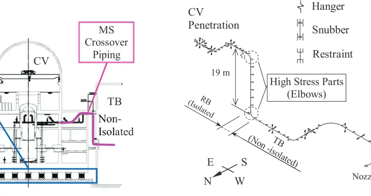
Many kinds of crossover piping must be arranged in the RB seismically Isolated Boiling Water Reactor (RBIBWR), which has a seismic isolation system for only RB as shown in Figure 1. The layout of MS crossover piping is shown in Figure 2. The authors thought applying flexible joints to MS crossover piping would be difficult and opted instead to apply a flexible piping layout. MS crossover piping has a 19 m vertical pipe part, as shown in Figure 2, which can deform horizontally and follow the relative displacement between RB and TB. The two elbows at the upper and lower ends of the vertical pipe are subject to high stress from the seismic response and relative displacement between RB and TB. It is also well known that elbow strength is dominated by in-plane bending. Accordingly, the relative displacement in the EW direction, as shown in Figure 2, could affect the elbows’ strength. For the seismic design of this MS crossover piping, the responses of the buildings in an EW direction prevailed.
The 1st to 4thvibration modes of MS crossover piping are shown in Figure 3. The fundamental frequency is 2.88 Hz, which is considerably lower than that of conventional seismic designed piping, because the flexibility to follow the large relative displacement between RB and TB reduces the natural frequency.
Seismic Isolation Systems
MS Crossover
Piping
Non- Isolated RB
CV
TB
Non Isol
Figure 1. Seismically isolated RB of a BWR plant
㻌
19 m
㻌
High Stress Parts (Elbows) CV
㻌
Penetration
㻌
Snubber㻌
Restraint
㻌
Hanger㻌
Nozzl
N
㻌
S
㻌
E㻌
W
㻌
The vertical pipe at the boundary between RB and TB vibrates horizontally and vertically in the vibration modes shown in Figure 3. The elbows at both ends of the vertical pipe undergo in-plane bending in the 2nd and 3rd modes and they are high-stress parts in MS crossover piping. These vibration modes are obtained from a model with unmovable supporting points but the supporting points of crossover piping move with seismically isolated RB.
EXCITATION TEST AND SIMULATION OF A 1/10 SCALE MODEL
Excitation test
Crossover piping of RBIBWR is shaken by both isolated RB and non-isolated TB seismic responses, while time-history analysis with multiple support motions has been verified by past studies. However, the crossover piping is deformed and excited by significant support motions. To verify the seismic response under such motions, a scale model shaking test of the MS crossover piping was performed. The details of the excitation test and the analysis have been presented by authors.
Scale models are usually designed using a similarity law, whereby with normal similarity, which simply scales length down, model acceleration increases beyond the performance of the shaking table. Meanwhile, a similarity law shown in Table 1, in which model acceleration can coincide with actual acceleration, has been adopted for the scaling model.
3rd: 3.69 Hz
4th: 4.49 Hz
Figure 3. Vibration mode of MS crossover piping
㻌
1st: 2.88 Hz2nd: 3.09 Hz
Table 2: Sizes of crossover piping
Crossover Piping
Outer diameter
[mm]
Thickness [mm]
Vertical length
[m]
Actual 762.0 38.1 19.06
Scale
model 76.3 4.2 1.906
Table 1: Similarity law for scale model Parameters Ratio, Test / Actual
Length 1/10
Mass 1/102
Frequency 100.5
Time 1/(100.5)
Displacement 1/10
Velocity 1/(100.5)
Acceleration 1
Stress 1
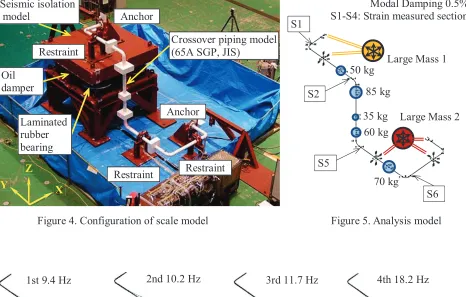
To replicate isolated RB vibration, the seismic isolation model shown in Figure 4 was used, which comprises a 10-metric ton mass made of steel, 4 laminated rubber bearings made of natural rubber, 2 oil dampers and a steel structure. It is difficult to manufacture a model pipe using the same forming method as an actual pipe, so a standard Japan Industrial Standards (JIS) pipe was used. Table 2 shows the diameters and thicknesses of the actual and model pipes. A scale model of the crossover piping shown in Figure 4 is supported by two anchors and three restraints fixed to the seismic isolation model and shaking table. The piping model is restrained in transverse horizontal and vertical directions at the restraints, where frictional force is also exerted in the axial direction of the pipe. The piping model has 5 additional masses due to the tune mass of the scale model according to similarity. Typical time histories of TB seismic response were used as excitation waves for the shaking test, while the response of the seismic isolation model shows low frequency and high damping response from rubber bearings and oil dampers. The scale model of cross over piping could be shaken by isolated and non-isolated response waves.
Seismic isolation model
Crossover piping model (65A SGP, JIS)
Anchor
Anchor
Figure 4. Configuration of scale model
Restraint Restraint
Restraint
X
㻌
Y㻌
Z
㻌
50 kg
85 kg
35 kg 60 kg
70 kg
Large Mass 1 Modal Damping 0.5% S1-S4: Strain measured section
Large Mass 2 S1
S2
S5
S6
Figure 5. Analysis model Laminated
rubber bearing Oil
damper
Figure 6. Vibration mode of scale model
㻌
FEM analysis
An analytical model for the crossover-piping scale model is shown in Figure 5. Two large masses were rigidly connected to the piping supports for inputs from the seismic isolation model and the shaking table. The vibration modes of the crossover piping model are shown in Figure 6 and are almost the same as those of the actual crossover piping shown in Figure 3. Moreover, the natural frequencies of scale model nearly correspond to those of the actual crossover piping calculated by similarity law.
Seismic response analysis of the crossover piping
By applying the displacements to two large masses, modal time-history analyses with multiple support motions were performed. MD NASTRAN was used for the analysis.
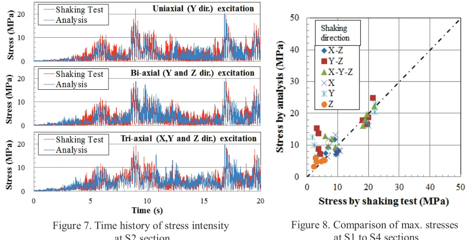
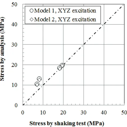
The stress time histories calculated from the strain measured at S2, which is the section near the upper elbow, are shown in Figure 7. The stress time histories by analysis are compared with the test results in this figure. The correlations between the maximum stresses at the four sections by the shaking tests and the analyses are shown in Figure 8. As shown in this figure, the analysis correlates well to the shaking test. The upper elbow becomes the part subject to highest stress because the in-plane bending dominates the elbow strength. As shown in Figure 7, stresses caused by Y, Y-Z and X-Y-Z excitation are similar, this means that the in-plane bending by Y excitation dominates.
The modal time-history analysis with multiple support motions was verified by comparing the stress by analysis with the stress by shaking tests in elastic level excitation. The non-linear analysis in elastic plastic level was also verified and fairly corresponded to shaking table tests. As a result, linear and non-linear time history analyses were verified by comparing with results of shaking table test.
SEISMIC RESPONSE ANALYSIS AND EVALUATION METHOD
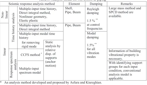
Seismic evaluation is closely connected with analysis method. The relation between analysis and evaluation for crossover piping is not different from its connection. The relations of analysis model, input condition, combination method and evaluation method with analysis method are summarized in Table 3 to 6.
Figure 8. Comparison of max. stresses at S1 to S4 sections
㻌
Time history analysis is the most detail analysis method and could simulate the seismic response of crossover piping. But uncertainties of seismic isolation system, soil and structure are not considered in time history analysis. Time history broadening described in ASME B&PV Code Sec. III, Appendix N is useful to consider the uncertainties.
Response spectrum analysis with multiple excitations requires combinations for responses by excitation directions and responses by multiple excitations. Moreover, a combination of response and deformation by anchor motion is also required. The appropriate combination methods were investigated by comparison with shaking table test. The result by applying SRSS for all combinations shown in Figure 8 is close to the result of shaking table test.
Fatigue evaluation from response spectrum analysis needs the required cycle which is an equivalent cycle of maximum stress level having the same fatigue damage as one by stress time history of seismic responses. The equivalent cycles for MS crossover piping was calculated as about 3 cycles. So it is considered that 10 cycles suffice to evaluate the fatigue of the crossover piping.
Table 3: Analysis model for MS crossover piping
Seismic response analysis method Element Damping Remarks
N
on
-li
ne
ar
Tim
e
hi
st
or
y
ana
lysi
s
Multiple-input time history, Direct integral method, Nonlinear geometry, Elastic plastic
Shell,
Pipe, Beam Rayleigh damping
1.5 % ** at control frequencies
Large mass method and SPCD method are available.
li
ne
ar
Multiple-input time history, Direct integral method
Pipe, Beam
Multiple-input modal time history
Modal damping
1.5% ** for all vibration modes for removing
rigid mode
Static analysis by relative disp. of supports (anchor motion)
R
espons
e
spe
ct
rum
ana
lysi
s
CCFS method *
Information of building vibrational property is necessary.
Multiple-input spectrum modal
With identifying support groups for each input condition, conventional analysis model is applicable. * An analysis method developed and proposed by Asfura and Kiureghian.
Table 4: Seismic input condition for MS crossover piping
Seismic response analysis method RB’s & TB’s responses Remarks Type Broadening *
N on -li ne ar Tim e hi st or y ana lysi s
Multiple-input time history, Direct integral method, Nonlinear geometry, Elastic plastic
Acc. or disp. time history. (Tri-axial for fault model earthquake Bi-axial for spectrum earthquake) Time history broadening or various time histories
Baseline correction of input time history is necessary for analysis by acceleration input. Multi-directional input is available.
li
ne
ar
Multiple-input time history, Direct integral method Multiple-input modal time history for removing rigid mode Static analysis by relative disp. of supports (anchor motion) Anchor motion Relative disp. variation
Relative disp. between RB and TB is expanded with softening of seismic isolation system. R espons e spe ct rum a na lysi s CCFS method Acc. FRS (Tri-axial for fault model earthquake Bi-axial for spectrum earthquake) Spectrum broadening
Single directional input is only available and combination of responses by each direction is necessary.
Multiple-input spectrum modal
* A method to account for the effect on structural frequency variation of the possible uncertainties in the material properties of seismic isolation system, the structure and soil.
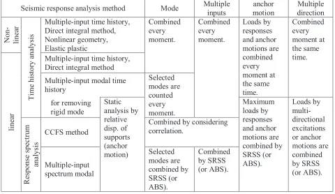
Table 5: Combination method for MS crossover piping
Seismic response analysis method Mode Multiple inputs anchor motion Multiple direction N on -li ne ar Tim e hi st or y ana lysi s
Multiple-input time history, Direct integral method, Nonlinear geometry, Elastic plastic Combined every moment. Combined every moment. Loads by responses and anchor motions are combined every moment at the same time. Combined every moment at the same time. li ne ar
Multiple-input time history, Direct integral method
Multiple-input modal time history Selected modes are counted every moment. for removing rigid mode Static analysis by relative disp. of supports (anchor motion) Maximum loads by responses and anchor motions are combined by SRSS (or ABS). Loads by multi-directional excitations or anchor motions are combined by SRSS (or ABS). R espons e spe ct rum ana lysi s CCFS method
Table 6: Evaluation method for MS crossover piping
Seismic response analysis method Collapse (Primary stress)
Shake down (Primary + Secondary)
Fatigue (Peak stress)
N
on
-li
ne
ar
Tim
e
hi
st
or
y
ana
lysi
s
Multiple-input time history, Direct integral method, Nonlinear geometry, Elastic plastic
At the present time, no evaluation criteria but collapse and ratchet deformation might be confirmed by analysis.
Strain time history and fatigue curve
li
ne
ar
Multiple-input time history,
Direct integral method Sprm <
min[3Shࠊ2Sy] *
Seismic response and dead load are considered. For no other mechanical load, above evaluation is exempted.
Sn < 2Sy *
Elastic
shakedown or not
For satisfying above evaluation, fatigue
evaluation is exempted.
Evaluation by peak stress time history and design fatigue curve.
Multiple-input modal time history
for removing rigid mode
Static analysis by relative disp. of supports (anchor motion)
S(neq/N) < 1 * Evaluation by required cycles neq and allowable cycles N
calculated from peak stress Sl and design fatigue curve.
R
espons
e
spe
ct
rum
ana
lysi
s
CCFS method
Multiple-input spectrum modal
* Evaluation by JEAC4601-2008 and JSME, S NC1-2012
CONCLUSION
For the seismically isolated LWR, large relative displacement between RB and TB occurs when only RB is seismically isolated and many piping systems must be arranged at the boundary of the two buildings. The crossover piping will be excited by the two buildings with different vibration characteristics. At the same time, the crossover piping will be deformed by the large relative displacement between RB and TB. To establish seismic response analysis and evaluation method, a scale model excitation test and the simulation were performed and time history analysis method was verified. The seismic response analysis involving multiple support motions or multiple excitations should be utilized for crossover piping.
The relations of analysis model, input condition, combination method and evaluation method with analysis method are summarized. To considered uncertainties of seismic isolation system, soil and structure for time history analysis, time history broadening is useful and available. And response spectrum analyses with multiple excitations and combination methods were investigated by comparing with shaking table test. Consequently, SRSS for all combinations could correspond to the shaking table test.
ACKNOWLEDGMENTS
This technological development was carried out as part of a national Japanese project “Development for Evaluation Methods of Seismic Isolation Systems” with the participation of Chubu Electric Power, Japan Atomic Power, Hokkaido Electric Power, Tohoku Electric Power, Tokyo Electric Power, Hokuriku Electric Power, Kansai Electric Power, Chugoku Electric Power, Shikoku Electric Power, Kyushu Electric Power, J Power, Toshiba, Hitachi-GE Nuclear Energy, Mitsubishi Heavy Industries, and the Institute of Applied Energy.
We would like to thank Dr. Nishikawa, Professor Emeritus at Tokyo Metropolitan University, Dr. Kubo, Professor Emeritus at the University of Tokyo, Dr. Fujita, Professor Emeritus at the University of Tokyo, Dr. Kasahara, Professor at the University of Tokyo and Dr. Yabana, at the Central Research Institute of Electric Power Industry for their advice.
REFERENCES
Asfura, A. and Kiureghian, A. (1986). “Floor Response Spectrum Method for Seismic Analysis of Multiply Supported Secondary Systems”, Earthquake Engineering and Structural Dynamics, Vol. 14, Page 245-265.
ASME B&PV CODE Sec. III, 2013, Appendix N, N-1222.3 Time History Broadening, N-1227: Multiple
Input Response Spectra Analysis and N-1228: Multiple Time History Excitations.
Bezler, P., Subudhi, M. and Hartzman, M. (1987). "Dynamic Analysis Independent Support Motion Response Spectrum Method", NUREG/CR-1677, Vol. 2, Aug. 1987.
Chiba, T., Koyanagi, R., Ogawa, N. and Minowa, C. (1987). "An experimental study of the multiple support piping systems", Proc. of 9th SMiRT, Lausanne, Switzerland, Aug. 1987, pp. 975-980. Chiu, H. C. (1997). “Stable Baseline Correction of Digital Strong-Motion Data”, Bulletin of the
Seismological Society of America, Vol. 87, No. 4, pp. 932-944.
JEAC4601-2008, Technical Code for Aseismic Design of Nuclear Power Plants, The Japan Electric
Association, in Japanese.
JSME S NC1-2012, Code for Nuclear Power Generation Facilities Rule on Design and Construction for
Nuclear Power Plants, in Japanese.
Kai, S., Kaneko, N. and Otani, A. (2012). "Analytical Study on Seismic Response of Piping under Multiple Support Excitations", ASME 2012 Pressure Vessels & Piping Division Conference, PVP2012-78203.
Kai, S., Watakabe, T., Kaneko, N., Tochiki, K., Moriizumi, M. and Tsukimori, K. (2013). "Study on Piping Response under Multiple Excitation, Part2: Validation for Multiple Analysis of Piping",
Kasawara, R. P. and Peck, D. A. (1973). "Dynamic Analysis of Structural Systems Excited at Multiple Support Locations", ASCE 2nd Specialty Conference on Structural Design of Nuclear Plant
Facilities, Chicago, IL, Dec. 1973, pp. 73-88.
Otani, A., Otoyo, T., Hirai, H., Iiizumi, H., Shimizu, H., Saitoh, M. and Onishi, S. (2014). “Development of an Evaluation Method for Seismic Isolation Systems of Nuclear Power Facilities (Part 3), Seismic Response of Crossover Piping for Seismic Isolation System”, ASME 2014 Pressure Vessels
& Piping Division Conference, PVP2014-29012.
Otoyo, T., Otani, A., Fukushima, S., Jimbo, M., Yamamoto, T., Sakakida, T. and Onishi, S. “Development of an Evaluation Method for Seismic Isolation Systems of Nuclear Power Facilities (Part 4), Failure Behavior of Crossover Piping for Seismic Isolation System”, ASME 2014 Pressure Vessels &
Piping Division Conference, PVP2014-29011.
Shaw, D. E. (1975). "Seismic Structural Response Analysis for Multiple Support Excitation", Proc. of 3rd
SMiRT, London, UK, 1975, K7/3 pp. 1-8.
Suzuki, Y., Sato, K., Iiizumi, H., Hisatsune, M. and Onishi, S. (2014). “Development of an Evaluation Method for Seismic Isolation Systems of Nuclear Power Facilities (Part 1), The Work Schedule of Project and a Seismic Design of Crossover Piping System”, ASME 2014 Pressure Vessels & Piping
Division Conference, PVP2014-29035.
Tai, K., Sasajima, K., Fukushima, S., Takamura, N. and Onishi, S. (2014). ”DEVELOPMENT OF AN EVALUATION METHOD FOR SEISMIC ISOLATION SYSTEMS OF NUCLEAR POWER FACILITIES (PART 2), APPLICATION OF CCFS METHOD TO THE MULTIPLY SUPPORTED SYSTEMS”, ASME 2014 Pressure Vessels & Piping Division Conference, PVP2014-28999.
Thailer, H. J. (1976). "Spectral Analysis of Complex Systems Supported at Several Elevations", Journal
of Pressure Vessel Technology, May 1976, pp. 162-165.
Vashi, K. M. (1975). "Seismic Spectral Analysis of Structural Systems Subject to Nonuniform Excitation at Supports", 2nd ASCE Specialty Conference on Structural Design of Nuclear Power Plant
Facilities, Vol. 1-A, New Orleans, LA, Dec. 1975, pp. 188-211.
Watakabe, T., Kaneko, N., Aida, S., Otani, A., Moriizumi, M., Tsukimori, K. and Kitamura, S. (2013). "Study ON Piping Response under Multiple Excitation, Part1: Triple Shaking Table Test of Piping Having Three-Supporting Points", ASME 2013 Pressure Vessels & Piping Division Conference, PVP2013-97832.