Optimization of mechanical crimping to assemble tubular components
Manas Shirgaokar
a, Hyunjoong Cho
a, Gracious Ngaile
a, Taylan Altan
a,∗,
Jang-Horng Yu
b, John Balconi
b, Richard Rentfrow
b, W.J. Worrell
baERC for Net Shape Manufacturing, The Ohio State University, 339 Baker Systems, 1971 Neil Avenue, Columbus, OH 43210, USA bScience and Technology Group, Alliant Ammunition and Powder Company, Radford Army Ammunition Plant,
Route 114, P.O. Box 1, Radford, VA 24141-0096, USA
Abstract
The crimping process is used often in the assembly of tubular components. In this study, with the aid of the finite-element method (FEM), the mechanical crimping operation was evaluated and optimized for a specific application. The effect of various process variables, such as the geometry, alignment and stroke of the crimper and the friction at the crimper–tube interface were investigated. Thus, it was possible to optimize the process so that the effect of springback could be reduced and the assembly quality, as indicated by the pullout force, could be improved. The crimping process of a single-grooved rod with a tube was evaluated as a case study. Based on the FE simulations, it was possible to determine the optimum alignment and the optimum design for two types of crimper geometries.
© 2003 Elsevier B.V. All rights reserved.
Keywords: Assembly; Crimping; Pullout test; FEM
1. Introduction
Traditional joining methods use resistance spot-welding or fastening elements such as screws, pegs, rivets, bolts and nuts. Though screws, clamps and rivets are very commonly used, these can be costly and not very reliable over long pe-riods of time[1]. Thus, there has been a growing interest in fastening processes which do not require additional joining elements and which can be combined with adhesive joining techniques to yield reliable and inexpensive assemblies. This has resulted in considerable research work on assembly pro-cesses such as clinching, hemming and crimping. The main advantage of such processes is that they do not require any pre- or post-processing, since there is no heat or thermal dis-tortion involved [1]. Thus, pre-painted components can be used for the assembly operation. Another advantage is the absence of chips, dirt or fumes, which provides a safe and hazard-free work environment. Traditionally the design of clinching and crimping operations has relied on experience and costly trial-and-error experiments. This paper discusses the application of finite-element method (FEM) in evalua-tion of a mechanical crimping process in order to enhance the performance of the assembly by determining the opti-mum process and geometrical parameters. A case study of
∗Corresponding author.
E-mail address: altan.1@osu.edu (T. Altan). URL: http://www.ercnsm.org.
the crimping process used in manufacturing bullets is pre-sented.
In the present study, the bullet is considered as a cylindri-cal solid rod that must be assembled to the casing, which is essentially a tubular part with a specific geometry and ma-terial. Thus, during crimping, the bullet is lowered into a tubular casing to a predetermined depth, and then six seg-mented crimpers/dies are pushed into the tube/casing by hydraulic rams, forming the crimp (Fig. 1 ). The tube is deformed to fill a groove, which is machined on the solid cylinder. The crimp quality, which is critical to the final performance of the assembly, is evaluated by a test, which measures the force that is required to pull the rod from the tube, the so-called “pullout test”. A variation in the geo-metrical properties of the crimp will cause variations in the strength and quality of the assembly that must satisfy cer-tain specifications. During the pullout test, the tube rarely ruptures. However, when it does, the damage is normally near the crimp. Thus, the quality of the crimp is extremely important because it determines the quality of the assembly. A ruptured tube or an excessive amount of crimping would affect the function of the assembly, which can result in ex-cessive scrap and costs. Another application of the crimping operation is in the field of electrical engineering for assem-bling composite insulators, which are fast, replacing porce-lain ones in electrical applications. These insulators consist of a glass-reinforced polymer (GRP) rod with two metal end fittings, which are radially crimped onto it[2]. This process
¯
σ,ε¯ effective stress and effective strain
is similar to the bullet crimping case study discussed in this paper.
The principal objectives of the study were to determine: (a) The optimum alignment of the tool/crimper with respect
to the groove in the stock/rod (Fig. 2). The variation of this alignment influences the pullout force.
(b) The optimum tool/crimper geometry (Fig. 2). The opti-mum design is defined as one that gives maxiopti-mum pull-out force with minimum thinning of the tube wall. The crimping process used for the present assembly ap-plication could be considered as a hybrid process, since a sealant is used during crimping. This sealant is somewhat similar to an adhesive and is applied over the groove in the rod. Thus, the sealant affects the interface friction
condi-Fig. 1. Components before and after the crimping operation.
The tube used in the present application is extruded from steel. It is then heat treated and annealed to meet certain hardness requirements, which were specified for the required application. It was not possible to trace the history of all the steps that affected the hardening properties of the tube prior to the crimping operation. Thus, the hardness distribution in the crimped region was used to find a stress–strain curve for the tube material in the vicinity of the crimping area. The following relationship between the flow stress and hardness was used[3]:
¯
σ=Er
Hb
1.7Er
1/0.92
(1)
where Eris the reduced Young’s modulus defined asEr= E/(1−ν2),σ¯ the flow stress defined asσ¯ =Kε¯n, and Hb
the hardness (ksi). This equation is valid when Hb/Eris less
than 0.16 and can describe the relation between flow stress and hardness better than using a simple linear relation[4].
For elastic material data, Young’s modulus, E, and Poisson’s ratio,ν, for the tube material (steel) were chosen as follows:
E=206.842 GPa(30 000 ksi) and ν=0.3
For the description of plastic behavior of the tube material, a tensile stress–strain curve from steel in the annealed con-dition(σ¯ =130.8ε¯0.17ksi =901.834ε¯0.17MPa)was used. However, the origin of this curve was shifted by an amount of pre-strain (Fig. 3) calculated in the following way[5,6]. First, for each given hardness number on the upper part of the tube (crimping region), an equivalent flow stress value was calculated by usingEq. (1), which correlates the flow stress and the hardness.
By rewritingEq. (1)in terms of hardness and the reduced Young’s modulus, an equivalent flow stress value was cal-culated:
¯
σ=Er
Hb
1.7Er
1/0.92
Fig. 2. Alignment of the tool with respect to the groove in the rod.
whereHb=263 ksi=1813.32 MPa and reduced Young’s modulus = Er = E/(1−ν2). The corresponding plastic strain was found from the tensile stress–strain curve from the annealed steel, i.e.σ¯ =130.8ε¯0.17ksi:
εequiv.=exp
lnσ¯−lnK
n
=0.173
The elastic strain limit (i.e. strain at yielding) was calculated with 0.2% strain offset limit and the slope of the stress–strain curve in the elastic region.
εyield=ε0.2%+σY
E =0.002+
97.06
30 000=0.003
Then, the original stress–strain curve was shifted by the amount of the difference between the equivalent plastic strain and elastic strain limit (Fig. 3):
ε=εequiv.−εyield=0.173−0.003=0.17
Finally, the shifted curve (Fig. 4) had a new yield stress and a new slope of work hardening, which could approximately describe the behavior of plastic deformation in the upper part of the tube during the crimping process.
Fig. 3. Concept of flow stress curve shifting.
0 100 200 300 400 500 600 700 800 900 1000
0 0.1 0.2 0.3 0.4 0.5 0.6
True Strain
True Stress (MPa)
Original Flow Stress Modified Flow Stress
Fig. 4. Shifted flow stress curve for the upper part of the tube.
3. Determination of optimum crimper alignment
The optimum alignment between the crimper and the groove (in the stock/rod) was defined as one, which gave maximum pullout force with minimum straining and thin-ning of the tube[7].
With the aid of FEM, a parametric study of the crimping operation was conducted to identify the factors that affect the thinning distribution and the pullout force. These factors were identified as the alignment between the crimper and the groove (in the stock/rod), the tool stroke and the coeffi-cient of friction at the crimper–tube and rod–tube interfaces
[7]. Simulations were carried out for the crimping process, followed by the springback and the rod/bullet pullout test. The parameters used in the simulations are discussed below: (a) Crimper alignment (h)
µ= .
was used for the crimping and springback simulations because these operations are carried out in the presence of a lubricant whereas the pullout test is done under dry conditions, resulting in a metal-to-metal contact and hence larger friction.
3.1. FE simulation of crimping and springback
FEM was used to simulate the crimping, springback and the rod pullout test with different crimper geometries. The simulations were carried out using a commercial FEM code DEFORM. Due to the geometry of the rod–tube assembly, an axisymmetric analysis was carried out, i.e. only half of the cross-section was considered for simulations (Fig. 5).
The crimping process can be regarded as a sheet metal bending process where a certain amount of springback occurs due to elastic recovery during unloading. Thus,
Fig. 5. FE model used for crimping.
simulation of the crimping process, with a tool stroke of 1.016 mm (0.04 in.) was sufficient, as the data for the tool stroke of 0.953 mm (0.038 in.) could be obtained from the results of this simulation.
The springback or unloading process was simulated after the crimping process. The springback was simulated sepa-rately for each of the two tool strokes considered, i.e. 0.953 and 1.016 mm.
Since the springback occurs immediately after the crimp-ing process, while the crimpers are retracted, the same co-efficient of friction ofµ=0.08 was used in the springback simulation as in the crimping process.
3.2. FE simulation of the pullout test
During the simulation of springback, the crimper loses contact with the tube/casing wall while it is being retracted. This step was used to simulate the pullout test. As in the springback simulations, the strain history got carried for-ward into the pullout test simulations. The pullout test was simulated by removing the crimper and applying velocity to the rod/bullet in the positive Z direction (Fig. 2). Since the pullout test is carried out under dry conditions, a higher coefficient of friction is required. Thus, frictional values of
µ=0.2 and 0.3 were used to simulate the pullout test for each of the alignments considered.
3.3. Optimum crimper alignment
Fig. 6. Crimper with a round nose.
the values of the pullout force and thinning distribution is in-evitable. The optimum alignment for a round-nosed crimper with crimp head angleθand nose radius R was determined (Fig. 6). Due to the proprietary aspects of this study, the actual dimensions of the crimper are not given here.
3.3.1. Thinning distribution
The thickness of the tube/casing over the region of crimp-ing were obtained from the FEM code DEFORM after the simulation of crimping and springback. The resulting thin-ning and the increase in thinthin-ning with increase in the stroke were noted in each case.
A parabolic profile of the thinning distribution was ob-served (Fig. 7). Maximum thinning was observed when the crimper was aligned 0.508 mm above the centerline of the groove in the rod/bullet for both the tool strokes. When the tool stroke was 0.953 mm, minimum thinning was observed for the alignmentsh=0, 0.254 and 0.381 mm.
3.3.2. Optimum alignment for tool stroke =0.953 mm (0.038 in.)
The results of the pullout simulations carried out for the different alignments with a tool stroke of 0.953 mm were combined with the thinning distribution obtained for this stroke (Fig. 8) to determine the optimum range of alignment for the crimping process.
Fig. 8shows the pullout force and the thinning distribu-tion against the six alignments, at µ=0.2 and 0.3. It was
Fig. 7. Bar graph of percent thinning vs. the alignment of the crimper with respect to the centerline of the groove in the rod (bullet).
observed that the graph of thinning distribution reached a minimum value at alignments ofh=0.381 and 0.254 mm and at the centerline (h = 0 mm). The point, which gave maximum pullout force with minimum thinning, was con-sidered to be the optimum condition. Thus, the position of the crimper at the centerline was found to be optimum. The pullout force was found to be 25.46 kN (5.725 klbf) for a tool stroke of 0.953 mm andµ=0.2. When the friction co-efficientµ=0.3, the optimum value of alignment remained the same though the pullout force increased to 26.86 kN (6.04 klbf) (Fig. 8).
3.3.3. Optimum alignment for tool stroke=1.016 mm (0.04 in.)
The same procedure, as in the previous case of stroke of 0.9525 mm (0.0375 in.), was followed to obtain the op-timum alignment for a stroke of 1.016 mm (0.04 in.). For
µ=0.2, an optimum alignment of 0.254 mm above the cen-terline was observed (Fig. 9) which gave a pullout force of 25.61 kN (5.759 klbf) for a tool stroke of 1.016 mm. Forµ= 0.3, though the optimum alignment remained the same, the force achieved during pullout increased to 26 kN (5.847 klbf) (Fig. 9).
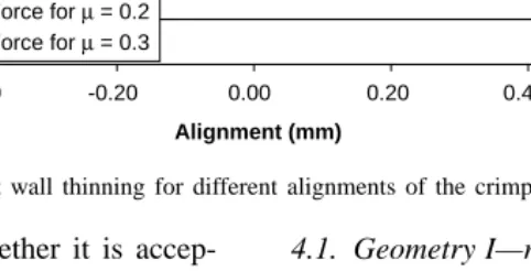
Figs. 8 and 9give the optimum values of crimper align-ment for the coefficients of friction of 0.2 or 0.3. However, it is possible to estimate the pullout force per alignment by interpolating or extrapolating between the present values of the coefficients of friction and for the values thought to be more appropriate for the process. For a tool stroke of 0.953 mm (Fig. 8), there was a region on the graph where the thinning remained at a minimum level of 6.06%. This gave a wider choice of pullout forces to choose from.
0 2 4 6 8 10 12 14 16 18 20 22
-0.60 -0.40 -0.20 0.00 0.20 0.40 0.60
Alignment (mm)
% Thinning
20 21 22 23 24 25 26 27 28
Pu
ll
out
For
ce
(K
N)
% Thinning
Pullout Force for µ = 0.2 Pullout Force for µ = 0.3
Fig. 9. Variation of pullout force and percent wall thinning for different alignments of the crimper tool for a stroke of 1.016 mm (0.04 in.).
thinning could be obtained to decide whether it is accep-table.
4. Evaluation of alternative die designs
Alternative die/crimper designs were evaluated based upon the results obtained from the determination of the op-timum alignment of the crimper with respect to the groove in the rod (bullet).
A parametric study of the crimping operation was con-ducted to determine the optimum crimp head geometry. The optimum geometry was defined as one that gives maximum pullout force with minimum thinning for the process con-ditions selected [8]. The process parameters used for this study were the same as those used for the study of optimum crimper alignment, i.e. the crimper alignment, the tool stroke and the friction between the rod–tube and crimper–tube in-terfaces. Two types of crimp head geometries were consid-ered for this study.
4.1. Geometry I—round-nosed crimpers
This geometry involved variants of a round-nosed crimper geometry, i.e. a crimp head with a round nose (Table 1). The parameters varied in this geometry were the crimp head an-gle (θ) and the nose radius (R). Five variants of this geometry
Table 1
Crimper design with a round nose
Geometry I End radius (R) Included angle (θ)
R1 θ1
R2 θ2
R3 θ3
R4 θ4
Table 2
Crimpers with a flat nose
Geometry II Flat nose (L) Included angle (θ)
L1 θ1
L2 θ2
L3 θ3
L4 θ4
were obtained by varying the angle and keeping the height of the crimp head (H) constant. Due to proprietary reasons, the actual dimensions of the nose radius (R) and the crimp head angle (θ) are not disclosed in this study.
The pullout force for each of these crimpers was cal-culated by running simulations for two alignments and these values were then compared to determine the optimum design.
4.2. Geometry II—flat-nosed crimpers
This geometry has a flat nose (Table 2). Four variations of this geometry were considered (Table 2) and the pull-out force was obtained from simulations conducted for two alignments. The crimp head height (H) and angle (θ) were maintained constant. Due to proprietary reasons, the actual dimensions of the flat nose (L) and the crimp head angle (θ) are not disclosed in this study.
4.3. Optimum design for the round-nosed crimper
Five variants of the round-nosed crimper design were con-sidered (Table 1). These designs were compared on the basis of the thinning distribution and the pullout forces. To de-termine the optimum crimper design, the results of the FE
Fig. 10. Variation of the pullout force and percent wall thinning for various round-nosed crimper designs (h=0.381 mm and tool stroke=0.953 mm).
simulations of the pullout tests for the two coefficients of friction (µ=0.2 and 0.3) were plotted with the thinning dis-tribution results for each tool stroke. The optimum crimper alignment was found to range between the centerline(h= 0)of the groove in the bullet to h=0.381 mm (0.015 in.) above the centerline. Only the results for an alignment of
h=0.381 mm are discussed here.
When the different variants of geometry I (round-nosed crimper geometry) were compared at the alignment of
h = 0.381 mm (0.015 in.) for a tool stroke of 0.953 mm (0.038 in.), the designs with crimp head angles θ2 andθ3 gave more or less the same maximum pullout force at fric-tion coefficient of 0.2 with minimum thinning of 6.06%. For a coefficient of friction of 0.3, the design with crimp head angleθ2was found to be optimum (Fig. 10).
For a tool stroke of 1.016 mm (0.04 in.), the design with crimp head angle θ2 gave the maximum pullout force for both the coefficients of friction. However, the crimpers with crimp head angles θ1 andθ3 could also be considered for the optimization of the crimping process since they gave minimum thinning while giving a considerable pullout force. The design with included angleθ5gave a high pullout force but also resulted in very high thinning of the tube at the crimped region (Fig. 11).
4.4. Optimum design for the flat-nosed crimper
Fig. 12. Variation of the pullout force and percent wall thinning for various flat-nosed crimper designs (h=0.381 mm and tool stroke=0.953 mm).
When the tool stroke was 0.953 mm (0.038 in.), all the designs considered had the same thinning distribution at the crimped region. The thickness of the tube/casing was re-duced by 18.18% (Fig. 12). The crimper design with a flat nose of L4in. was found to be optimum for both the
co-efficients of friction. For the coefficient of friction of 0.3, the pullout force achieved with this design was considerably greater than that achieved with the other crimpers.
The crimper with a flat nose of L3in. was optimum for
both the coefficients of friction for a tool stroke of 1.016 mm (0.04 in.) (Fig. 13). The simulation results showed a uni-form increase in the pullout force for each crimper when the friction was increased toµ=0.3. All the crimpers had the same thinning of 24.24% for this tool stroke.
5. Summary and conclusions
The crimping operation investigated in this study can be used for assembling tubular components without the use of additional joining elements. The mechanical crimping oper-ation of a bullet was considered as a case study. Parametric studies were conducted with the aid of FEM to study the effect of various process and geometrical parameters on the crimp quality.
The material properties of the tube/casing were de-termined from the hardness distribution measured in the crimped region. The flow stress data thus obtained was used as an input for the simulations to evaluate the crimper alignment and geometry for different process conditions.
The major conclusions drawn from this study are: 1. The average optimum value of the crimper alignment is
0.254 mm (0.01 in.) above the centerline of the groove in the rod (bullet) for a tool stroke of 1.016 mm (0.04 in.). 2. For a stroke of 0.953 mm (0.038 in.), the optimum value
of the crimper alignment ranges between the centerline and 0.381 mm (0.015 in.) above the centerline. This is true under the assumed interface coefficients of friction used in the simulations.
3. For geometry I (round-nosed crimpers), at the alignment of h =0.381 mm above the centerline of the groove in the rod/bullet, the crimper design with crimp head angle
θ2was found to be optimum. However, at this alignment, for a tool stroke of 1.016 mm, the designs with a crimp head angle of θ1 andθ3were also possible choices for the optimization of the crimping process.
4. For geometry II (flat-nosed crimpers), at the alignment of 0.381 mm, the crimper with a flat nose of L4in. was found
to be optimum at a tool stroke of 0.9525 mm for both the coefficients of friction. For a tool stroke of 1.016 mm, the design with a flat nose of L3in. gave the optimum results
for both the coefficients of friction.
5. It is evident from the results that the effect of coeffi-cient of friction used in the FE simulations of the pull-out tests was significant. The friction conditions could affect the selection of the optimum design to a large ex-tent. Thus, the lubrication conditions at the rod–tube and crimper–tube interfaces are very critical for optimizing the mechanical crimping process.
6. It was thus concluded that a parametric study of the process and geometrical parameters could successfully determine the optimum design for crimping tubular components.
Acknowledgements
The authors wish to thank the Alliant Ammunition and Powder Company, Radford Army Ammunition Plant, VA, USA for funding this study.
References
[1] J.P. Varis, The suitability of round clinching tools for high strength structural steel, Thin Walled Struct. 40 (2002) 225–238.
[2] A. Bansal, A. Schubert, M.V. Balakrishnan, M. Kumosa, Finite-element analysis of substation composite insulators, Composite Sci. Technol. 55 (1995) 375–389.
[3] S. Jayaraman, G.T. Hahn, W.C. Oliver, C.A. Rubin, P.C. Bastias, Determination of monotonic stress–strain curve of hard materials from ultra-low-load indentation tests, Int. J. Solid Struct. 35 (1998) 364– 382.
[4] D. Tabor, The Hardness of Metals, Clarendon Press, Oxford, 1951. [5] H.D. Chandler, J.-N. Gortzen, Kinetics of tensile deformation in a
precipitation-hardened aluminum alloy, Mater. Sci. Eng. A 188 (1994) 97–102.
[6] H. Cho, S. Saxena, Stress analysis and evaluation of a bullet crimping process, Progress Report I, Report no. ERC/NSM-00-48, 2000. [7] M. Shirgaokar, G. Ngaile, H. Cho, T. Altan, Stress analysis and
evaluation of a bullet crimping process, Progress Report II, Report no. ERC/NSM-00-48-B, 2001.