Control of PMSM using Neuro-Fuzzy Based
SVPWM Technique
K.Meghana 1, Dr.D.Vijaya kumar 2, I.Ramesh 3, K.Vedaprakash4
P.G. Student, Department of EEE, AITAM Engineering College (Autonomous), Andhra Pradesh, India1
Professor, Department of EEE, AITAM Engineering College (Autonomous), Andhra Pradesh, India2
Sr. Asst. Professor, Department of EEE, AITAM Engineering College (Autonomous), Andhra Pradesh, India3
P.G. Student, Department of EEE, AITAM Engineering College (Autonomous), Andhra Pradesh, India4
ABSTRACT: In the present scenario, static frequency converter based variable speed synchronous motors has become very familiar and advantage to other drive system, especially low speed and high power applications. Unlike the induction motor, the synchronous motor can be operated at variable power factor (leading, lagging or unity) as desired. So, there is an increasing use of synchronous motors as adjustable speed drives. Static power sources are now available with DC link inverters of voltage source (VSI) or current source (CSI) type and cyclo converters. The use of pulse width modulation (PWM) technique in case of VSI drives allows efficient and smooth operation, free from torque pulsations and cogging, lower volume and weight and provides a higher frequency range compared to CSI drives. Even for voltage source inverter, the commutation circuit is not needed, if the self-extinguishing switching devices are used. This paper proposes a concept of Neuro-fuzzy based control strategy which is used for controlling the PMSM. The total work mainly concentrates on optimum control of PMSM with maximum voltage utilization with less switching losses.
KEYWORDS: PMSM, Mathematical modeling, FOC, Direct Torque Control, Pulse Width Modulation, Voltage Source Inverter.
I. INTRODUCTION
In last few decades, an electric ac machine plays a key role in industrial progress. All kinds of electrical ac drives have been developed and applied, the basic applications of this drive as manufacturing industries such as conveyer belts, cranes and paper mills etc. In the present scenario, for industrial driving systems a new advanced technology has been preceded. The main aim of this technology is to improve the dynamic performance and efficiency of the system by changing the switching frequency.
The control technique for electric motor is classified into two cases depends on the control parameters such as scalar control and vector control. In scalar control, it controls only magnitude of the system. In this technique the v/f term is maintained constant. In scalar control we have poor dynamic performance of the drive system. The higher dynamic performance can be achieved only by control of both magnitude and flux and it possible only with help of vector control. Like, current-regulated separately excited DC motor, in vector control for PMSM where, the torque is proportional to the product of flux and armature current. Similarly, in PMSM the controlling of torque can be achieved by controlling of estimation flux and current.
parameter variations and external disturbances, which can guarantee perfect tracking performance de-spite parameters or model uncertainties.
Then, to further improve the disturbance rejection performance of SMC method, extended sliding-mode disturbance observer (ESMDO) is proposed, and the estimated system disturbance is considered as the feed forward compensation part to compensate sliding-mode speed controller. Thus, a composite control method combining an SMC part and a feed forward compensation part based on ESMDO, called SMC+ESMDO method, is developed. Finally, the effectiveness of the proposed control approach was verified by simulation and experimental results.
During the last decade, permanent magnet synchronous motors have been used widely in the industry to replace DC motors and induction machines. The main characteristics of these motors are the low inertia, the high efficiency, power density and reliability. Due these advantages, permanent magnet synchronous motors are ideal for the applications where a quick accurate torque control is required.
II. RELATED WORK
The Permanent Magnet Synchronous Motor is a rotating electric machine where the stator is a classic three phase coils like that of an induction motor and the permanent magnets are located on the rotor surface. A PMSM provides rotation at a fixed speed in synchronization with the frequency of the power source, regardless of the fluctuation of the load or line voltage. The motor runs at a fixed speed synchronous with mains frequency, at any torque up to the motor’s operating limit. These types of machines are extensively used in servo drives for low power machine tool, e.g. robots, positioning devices etc. They are receiving increased attention by possibility to use in the region of larger power e.g. electricity generation. The following requirements for servo drives must be served:
• High possible power to weight ratio,
• Large torque to inertia ratio – high acceleration possible, • Smooth torque in wide speed – small pulsation of speed, • Full torque at zero speed – stand still working,
• High speed operation,
• Compact design and small size.
New types of Permanent Magnet materials offer the ability to design electromagnetic energy converters with complicated shapes. Permanent magnets can be sticked or inserted to the small rotor. Rare-earth magnets are mostly used in modern drive.
PMSM are used in high-accuracy direct-drive applications mainly due to their advantages.
Compared to conventional DC motors, they have no brushes or mechanical commutators, which eliminate the problems due to mechanical wear of the moving parts. In addition, the better heat dissipation characteristic and ability to operate at high speed render them superior to the PMSM drives.
III. CONTROL STRATEGIES FOR PMSM
For achieving better higher dynamic performance and high efficiency, the vector control is shows better solution than scalar control. The control strategies for PMSM are divided in two cases such as DTC & FOC controller.
DIRECT TORQUE CONTROL (DTC)
In DTC controller, in case of PMSM armature current is consider as reference parameter for controlling torque. Then armature current is converted into dq reference frame for achieving better dynamic performance of PMSM. DTC is one of the methods that have emerged to become one of the best alternative solutions to the Vector Control for Motors. This method gives a better performance with a simpler structure and control diagrams [4]. In case of DTC, the stator flux and torque can be control directly by selecting proper VSI states. The main advantage of 3-leg VSI topology is to increase in the number of voltage vectors.
Fig 2: Scheme of SVPWM based on DTC for PMSM
Like vector control of conventional DFIG, the dc-link voltage control of PMSG also needs some extra considerations. In this the power extracted in the inverter flows through stator windings, the dc-link voltage of converter relies only on the rotor power Ps [8], obtained from the stator windings.
(1)
(2)
(3)
(4)
(5)
(6)
The power generated in PMSG is represented by Iqr. The stableness of the dc link voltage is more momentous.
Therefore, preference for controlling parameter is given to output of dc link voltage Idr* [9].
(7)
(8)
SVPWM
SVPWM is one of the techniques in pulse width modulation technique for generating gate signals based on the space vectors generated by the system in the form of two-phase vector components instead of general pulse width modulation [12]. The space vector diagram for proposed system with range of space vectors from S1 to S6 is as
Figure 3: Space Vector Modulation Technique
Generally, for three phase inverters the SVPWM is one of the best method in general pulse width modulation techniques. The implementation procedure steps for SVPWM technique [13]:
1. First convert three phase quantities to two phase co-ordinates. 2. Identify the times T1, T2 and T0.
The reference voltage vector is obtained by the equation (1),
V* Tz = S1*T1 + S2 *T2 + S0 *(T0/2) + S7 *(T0/2) (1)
Where T1, T2 are time intervals for space vectors S1 and S2 respectively, and zero vectors S0 and S7 has time interval of T0.
FUZZY LOGIC CONTROLLER
In the previous section, control strategy based on PI controller is discussed. But in case of PI controller, it has high settling time and has large steady state error.
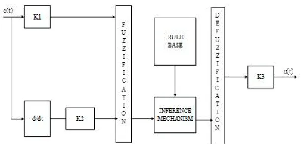
In order to rectify this problem, this paper proposes the application of a fuzzy controller shown in Figure 4. Generally, the FLC is one of the most important software based technique in adaptive methods.
As compared with previous controllers, the FLC has low settling time, low steady state errors. The operation of fuzzy controller can be explained in four steps.
1. Fuzzification
2. Membership function
3. Rule-base formation
4. Defuzzification.
In this paper, the membership function is considered as a type in triangular membership function and method for defuzzification is considered as centroid. The error which is obtained from the comparison of reference and actual values is given to fuzzy inference engine. The input variables such as error and error rate are expressed in terms of fuzzy set with the linguistic terms VN, N, Z, P, and Pin this type of mamdani fuzzy inference system the linguistic terms are expressed using triangular membership functions. In this paper, single input and single output fuzzy inference system is considered. The number of linguistic variables for input and output is assumed as 3.
Artificial Neural Networks
Figure 5 shows the basic architecture of artificial neural network, in which a hidden layer is indicated by circle, an adaptive node is represented by square. In this structure hidden layers are presented in between input and output layer, these nodes are functioning as membership functions and the rules obtained based on the if-then statements is eliminated. For simplicity, we considering the examined ANN have two inputs and one output. In this network, each neuron and each element of the input vector p are connected with weight matrix W.
Step by step procedure for implementing ANN:
1. Identify the number of input and outputs in the normalized manner in the range of 0-1. 2. Assume number of input stages.
3. Identify number of hidden layers.
4. By using transig and poslin commands create a feed forward network. 5. Assume the learning rate should be 0.02.
6. Choose the number of iterations. 7. Choose goal and train the system.
9. Generate the simulation block by using ‘genism’ command
Figure 5: Architecture for ANN
IV. SIMULATION DIAGRAM AND RESULTS
The performance of the proposed PMSM model with SMC and Neuro-Fuzzy Controller is observed by using Matlab/Simuink. The simulation results of the SMC method and NEURO-FUZZY controller are shown in below Figures.
Fig 6: Speed and Electromagnetic Torque for PMSM machine with SMC controller
the simulation result for Electromagnetic Torque of the machine under SMC controller. From the waveform we observed that the ripple in Electromagnetic Torque has been improved as compared with conventional PI controller. And figure 7 shows the waveform of harmonic distortion factor for direct axis current.
Fig 7: THD waveform for direct axis current
Fig 8: Waveform for Speed and torque of PMSM machine with SMC-NEURO-FUZZY controller
The simulation result for Electromagnetic Torque of the machine under SMC-NEURO-FUZZY controller. From the waveform we observed that the ripple in Electromagnetic Torque has been improved as compared with conventional SMC controller. And figure 9 shows the waveform of harmonic distortion factor for direct axis current
Fig 9: THD waveform for direct axis current
V. CONCLUSION
In this paper, an SMC based PMSM system along with Neuro-Fuzzy controller is proposed and has been successfully verified. The main aim of this Neuro-Fuzzy controller is to compensate the sudden disturbances. The major contribution of this extended sliding mode controller is to estimate the system disturbances. From the simulation results we conclude that the proposed SMC based Neuro-Fuzzy controller, effectively damps the system disturbances as compared with the conventional SMC controller.
REFERENCES
[1] Y. X. Su, C. H. Zheng, and B. Y. Duan, “Automatic disturbances rejection controller for precise motion control of permanent-magnet
[2] X. G. Zhang, K. Zhao, and L. Sun, “A PMSM sliding mode control system based on a novel reaching law,” in Proc. Int. Conf. Electr. Mach. Syst., 2011, pp. 1–5.
[3] W. Gao and J. C. Hung, “Variable structure control of nonlinear systems: A new approach,” IEEE Trans. Ind. Electron., vol. 40, no. 1, pp. 45–
55, Feb. 1993.
[4] G. Feng, Y. F. Liu, and L. P. Huang, “A new robust algorithm to improve the dynamic performance on the speed control of induction motor
drive,” IEEE Trans. Power Electron., vol. 19, no. 6, pp. 1614–1627, Nov. 2004.
[5] Y. A.-R. I. Mohamed, “Design and implementation of a robust current control scheme for a pmsm vector drive with a simple adaptive
disturbance observer,” IEEE Trans. Ind. Electron., vol. 54, no. 4, pp. 1981–1988, Aug. 2007.
[6] M. A. Fnaiech, F. Betin, G.-A. Capolino, and F. Fnaiech, “Fuzzy logic and sliding-mode controls applied to six-phase induction machine with
open phases,” IEEE Trans. Ind. Electron., vol. 57, no. 1, pp. 354–364, Jan. 2010.
[7] Y. Feng, J. F. Zheng, X. H. Yu, and N. Vu Truong, “Hybrid terminal sliding mode observer design method for a permanent magnet
synchronous motor control system,” IEEE Trans. Ind. Electron., vol. 56, no. 9, pp. 3424–3431, Sep. 2009.
[8] H. H. Choi, N. T.-T. Vu, and J.-W. Jung, “Digital implementation of an adaptive speed regulator for a pmsm,” IEEE Trans. Power Electron.,
vol. 26, no. 1, pp. 3–8, Jan. 2011.
[9] R. J.Wai and H. H. Chang, “Back stepping wavelet neural network control for indirect field-oriented induction motor drive,” IEEE Trans. Neural Netw., vol. 15, no. 2, pp. 367–382, Mar. 2004.
[10] G. H. B. Foo and M. F. Rahman, “Direct torque control of an ipm synchronous motor drive at very low speed using a sliding-mode stator flux
observer,” IEEE Trans. Power Electron., vol. 25, no. 4, pp. 933–942, Apr. 2010.
[11] D. W. Zhi, L. Xu, and B. W. Williams, “Model-based predictive direct power control of doubly fed induction generators,” IEEE Trans. Power
Electron., vol. 25, no. 2, pp. 341–351, Feb. 2010.
[12] K. Zhao, X. G. Zhang, L. Sun, and C. Cheng, “Sliding mode control of high-speed PMSM based on precision linearization control,” in Proc.
Int. Conf. Electr. Mach. Syst., 2011, pp. 1–4.
[13] C.-S. Chen, “Tsk-type self-organizing recurrent-neural-fuzzy control of linear micro-stepping motor drives,” IEEE Trans. Power Electron., vol.
25, no. 9, pp. 2253–2265, Sep. 2010.
[14] M. Singh and A. Chandra, “Application of adaptive network-based fuzzy inference system for sensorless control of PMSG-based wind turbine
with nonlinear-load-compensation capabilities,” IEEE Trans. Power Electron., vol. 26, no. 1, pp. 165–175, Jan. 2011.
BIOGRAPHY
Ms.K.Meghana received his B.Tech Degree in Electrical and Electronics Engineering from Sri Sivani College of engineering, Srikakulam, Andhra Pradesh, India in 2014. Currently pursuing M.Tech in Aditya Institute of Technology and Management,(Autonomous), Tekkali, Andhra Pradesh, India. His research interests include Renewable energy systems and power electronics.
Dr.D.Vijaya Kumar completed his graduation in Electrical and Electronics Engineering from Andhra University, Visakhapatnam in 1997 and received his M.E.in Power Systems from Andhra University, India in 2000.He served as an Assistant Professor and Associate Professor in various Engineering colleges during 2000-2010 and at present, he is working as a Professor in the Department of Electrical and Electronics Engineering in AITAM College of Engineering, Tekkali, Andhra Pradesh, India. He had published many papers in national and international journals and conferences. His areas of interest are Power systems and Control systems.
Mr.I.Ramesh completed his graduation in electrical and electronics engineering from JNTUH, in 2006 and received his M.Tech from JNTUK in 2011.Presently working as Sr.Asst.Proffesor in the Department of Electrical and Electronics Engineering in Aditya Institute of Technology and Management,(Autonomous), Tekkali, Andhra Pradesh, India. His areas of interest are Power systems, power electronics and applications.