Analytical Study on LDSS Channel Column
Sections
Sutar Nikhil B.1, Mohite Prakash M.2
P.G. Student, Department of Civil Engineering, Rajarambapu Institute of Technology, Sakhrale, Maharashtra, India1 Associate Professor, Department of Civil Engineering, Rajarambapu Institute of Technology, Sakhrale, Maharashtra,
India2
ABSTRACT: In actual practice stainless steel is used in a marine and extreme condition. Stainless steel posses high strength and better corrosion resistant properties. The reason is due to high cost of stainless steel. Lean duplex stainless steel (LDSS) sections are being used popularly in shops, factories, automobile engineering and industries on account of their high strength to weight ratio, simplicity in construction, flexibility in fabrication and high structural efficiency. A lot of research work has been carried out to study the structural behaviour of doubly symmetric LDSS column sections considering different parameters. However, structural behaviour of singly symmetric LDSS column sections considering axial loading has not received much attention. In this work the effect of slenderness ratio, cross section aspect ratio and corner radius to material thickness on the load carrying capacity is observed. Finite element analysis of the section is also done using ABAQUS software for determining the effect of slenderness ratio, cross section aspect ratio and corner radius to material thickness on the L.C.C and buckling behaviour of the channel column sections.
KEYWORDS: Axial loading, Cross section aspect ratio, Corner radius to material thickness ratio, Finite element analysis, LDSS, Slenderness ratio.
I. INTRODUCTION
Thin sheet steel products are extensively used in all aspects of modern life; in the shop, factory, automobile engineering and industry. The LDSS have better properties than the authentic ferrite steel and carbon steel. LDSS has high strength to the weight ratio, high corrosion resistance, aesthetic properties are better. The disadvantage of using the LDSS sections is cost and ductility. Cost is two times that of stainless steel. And due to high strength it is difficult to prepare the sections from cold forming process. These thin steel sections with thickness between 1mm to 8mm are cold-formed, i.e. their manufacturing process involves forming steel sections in a cold state from steel sheets of uniform thickness. The advantages of using LDSS sections are high strength-to-weight ratio, easy for construction and flexibility in fabricating different cross section shapes. Lean duplex stainless steel sections usually manufactured into hat sections, channel sections, Z-sections by cold-rolling or brake-pressing technique. Lean Duplex Stainless Steel Columns (LDSSC) are highly susceptible to instability phenomena such as local, distortional and global (flexural or flexural torsional) buckling. Depending on the column geometry (cross section and length) and end support conditions, its post-buckling behaviour and ultimate strength may be significantly affected by interactions involving various post-buckling modes.
II. ANALYTICAL STUDY
The numerical study has been carried out considering LGSCC of different sizes EC3 (EN1993 part 1-4).factors affecting the slenderness ratio are cross section area, dimensions of web, dimension of flange, support condition and length of column. Therefore out of the five variables the length is varied from 500mm to 600 mm and due to that change in the slenderness ratio is observed. To determine the effect of cross section aspect ratio on the load carrying capacity of the section the area is kept constant and other two dimensions of the flange and web varied. In Indian code the effect of corner radius are considered to determine the ultimate compressive load. To determine the effect of corner radius and material thickness on the load carrying capacity the corner radius is varied. To determine the location of load for maximum ultimate load, the load position moves -10 mm to 20 mm from C.G of channel section.
III.NUMERICAL STUDY
The finite element analysis of light gauge steel lipped channel column section has done by using finite element analysis software ABAQUS version 6.10-1. The channels were modelled using shell element S4R. The columns were analysed for hinged-fixed boundary condition. Tetrahedron mesh type has used for meshing of model. Elastic
modulus (E) = 2.0x10⁵ N/mm2 and Poisson ratio (μ) = 0.3 were used as material properties. Tetrahedron mesh
type has used for meshing of element. The fig.1 shows steps have been used for finite element analysis by using ABAQUS software.
Figure1. Shows stepwise procedure in FEM software
IV.RESULTS AND DISCUSSION
The results obtained by Euro Code (EC3) and finite element analysis software ABAQUS are compared below. a)Ultimate compressive load for channel column by varying slenderness ratio
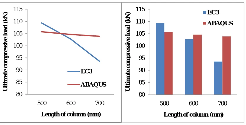
To study effect of varying slenderness ratio on ultimate compressive load of channel column section test were carried out on LDSSCC sections of length 500mm to 700mm with eccentricity 0 mm. The results obtained by Euro Code (EC3) and ABAQUS software are tabulated in table 1.
Part
Property
Assembly
Step
Load
Mesh
Table 1Ultimate compressive load for channel column section by varying slenderness ratio
Sr. No Section size Slenderness ratio
Ultimate compressive load (kN) Error %
EC3 ABAQUS
1 75 X 40 X 2 L500 40.47 109.37 105.72 3.38
2 75 X 40 X 2 L600 48.56 102.78 104.62 3.02
3 75 X 40 X 2 L700 56.66 93.56 103.91 9.96
From Table 1, it is observed that as length of column increases the ultimate compressive load increases. The error between the analytical and numerical result is up to 10%. As slenderness ratio increases the value of ultimate load decreases from 105.72 to 103.91 in ABAQUS.
Figure 2 Ultimate compressive loads for varying length
Figure 2 show the variation of ultimate compressive strength vs length of column. From fig it can be seen that as length of column increases its ultimate compressive strength decreases.
b)Ultimate compressive load for channel column by varying cross section aspect ratio.
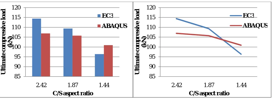
To study the effect of varying cross section aspect ratio on the load carrying capacity of the LDSSCC section , the cross section aspect ratio is varied from 1.44 to 2.44 keeping area same. The results obtained by Euro Code (EC3) and ABAQUS are shown in Table 2.
80 85 90 95 100 105 110 115
500 600 700
U
lti
m
ate
c
o
m
p
r
e
ss
iv
e
l
o
ad
(k
N
)
Length of column (mm) EC3
ABAQUS
80 85 90 95 100 105 110 115
500 600 700
U
lti
m
ate
c
o
m
p
r
e
ss
iv
e
l
o
ad
(k
N
)
Length of column (mm) EC3
Table 2Ultimate compressive load for channel column section by varying cross section aspect ratio
Sr. No
Section size
C/S aspect ratio
Ultimate compressive load (kN)
Error %
EC3 Abaqus
1 85 X 35 X 2 L500 2.42 114.37 106.90 26.53
2 75X 40 X 2 L500 1.87 109.37 105.72 3.34
3 65 x 45 x 2 L500 1.44 96.37 100.89 7.45
From Table 2, it is observed that as a cross section aspect ratio decreases value of ultimate compressive load decreases. The value of cross section aspect ratio effects on the stiffness of the channel section that results in change in ultimate compressive load. The value of ultimate compressive load decreases from 106.90 to 100.89 in ABAQUS.
Figure 3 ultimate compressive load for channel column section for varying aspect ratio
From Figure 3 it can be seen that as c/s aspect ratio decreases its load carrying capacity decreases.
c)Ultimate compressive load for channel column by varying cross section corner radius to material thickness ratio. To study the effect of varying corner radius to material thickness ratio on the load carrying capacity of LDSSCC section, corner radius to material thickness is varied from 1.58 to 2.18. The results are shown in table 3.
Table 3 Ultimate compressive load for channel column section by varying corner radius to material thk.ratio
Sr. No
Section size Corner radius to material thickness ratio
Ultimate compressive load Abaqus (kN)
1 75 X 35X 2 L500 R3.17 1.58
105.1
2 75X 35 X 2 L500 R3.57 1.78 103
3 75X 35 X 2 L500 R3.96 1.98 99.8
4 75 X 35 X 2 L500 R4.36 2.18 98.5
85 90 95 100 105 110 115 120
2.42 1.87 1.44
U lti m ate c o m p r e ss iv e l o ad (k N )
C/S aspect ratio
EC3 ABAQUS 85 90 95 100 105 110 115 120
2.42 1.87 1.44
U lti m ate c o m p r e ss iv e l o ad (k N )
C/S aspect ratio
EC3
Figure 4 Ultimate compressive loads for varying corner radius to material thickness ratio
From Figure 4 it can be seen that as corner radius to material thickness ratio increase its load carrying capacity decreases.
d)Test to determine proper location of load for maximum load carrying capacity of the LDSSCC section.
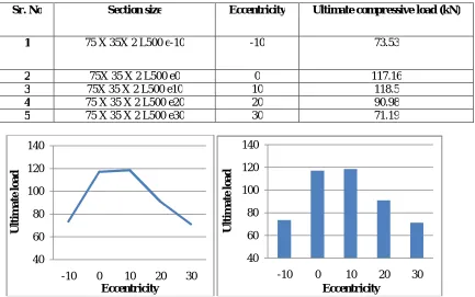
In this, to observe the effect of load position on the ultimate load the load position is shifted in x direction towards or away from the C.G of a section. The name given to the section is 75x35x2L500e0 means the eccentricity is zero and load applied at the C.G of a section. Following results are obtained by changing the load positions.
Table 4 Ultimate compressive load for channel column section by varying load position (eccentricity)
Sr. No Section size Eccentricity Ultimate compressive load (kN)
1 75 X 35X 2 L500 e-10 -10 73.53
2 75X 35 X 2 L500 e0 0 117.16
3 75X 35 X 2 L500 e10 10 118.5
4 75 X 35 X 2 L500 e20 20 90.98
5 75 X 35 X 2 L500 e30 30 71.19
94 96 98 100 102 104 106
1.58 1.78 1.98 2.18
U
lti
m
ate
c
o
m
p
r
e
ss
iv
e
Lo
ad
(k
N
)
Corner radius to material thickness ratio ABAQUS
40 60 80 100 120 140
-10 0 10 20 30
U
lti
m
ate
l
o
ad
Eccentricity
40 60 80 100 120 140
-10 0 10 20 30
U
lti
m
ate
l
o
ad
From fig 5 and table 4 it is observed that as load moves towards the width of a web the value of ultimate compressive load increases. The value of ultimate compressive load is maximum at 10 mm eccentricity means near the web. The position at load is on the web the ultimate compressive load is maximum.
V. CONCLUDINGREMARKS
After studying the effects of various parameters on the ultimate compressive load, the following concluding remarks are observed.
a) The ultimate compressive load decreases with increase in slenderness ratio of the channel section. Average 9% increase in slenderness ratio results average 0.8% decrease in ultimate load.
b) The ultimate compressive load increases as the position of load moves towards the supported edge of the channel section. Maximum ultimate load is obtained when it is applied over the thickness of web.
c) Ultimate compressive load increases with decrease in cross section aspect ratio. Average 23% increase in cross section aspect ratio results average 4% decrease in ultimate load carrying capacity of a section.
d) Ultimate compressive load of column decreases with increase in corner radius to material thickness ratio. Average 10% increase in corner radius to material thickness ratio results average 1.5% decrease in load carrying capacity.
e) Due to smaller thickness of section,columns fail due to local and distortional buckling.
REFERENCES
[1] Barbara Rossi (2014). “Discussion on the use of stainless steel in construction in view of sustainability. “Journal on Thin Walled Structures, Volume-83,182-189.
[2] Graham Gedge (2008). “Structural uses of stainless steel-building and civil engineering. “Journal of Constructional Steel Research, Volume-64, 1194-1198.
[3] Jorgen Becque, Kim J.R. Rasmussen (2009). “Experimental investigation of local-overall interaction buckling of stainless steel lipped channel columns. “Journal of Constructional Steel Research, Volume-65, 1677-1684.
[4] M. Ashraf, L. Gardner, D. A. Nethercot (2006). “Compression strength of stainless steel cross-sections. “Journal of Constructional Steel Research, Volume-62, 105-115.
[5] M. F. Hassanein (2011). “Finite element investigation of shear failure of lean duplex stainless steel plate girders.” Journal on Thin walled structures, Volume-49, 964-973.
[6] M. Lecce, K. J. R. Rasmussen (2006). “Distortional buckling of cold-formed stainless steel sections: Finite element modeling and design.” Journal of Structural Engineering, volume-132, 505-514.
[7] M. Longshithung Patton, Konjengbam Darunkumar Singh (2012).“Numerical modeling of lean duplex stainless steel hollow columns of square L-, T- and + shaped cross sections under pure axial compression.” Journal on Thin Walled Structures, Volume-53,1-8.
[8] M. Theofanous, L. Gardner (2009). “Testing and numerical modeling of lean duplex stainless steel hollow section columns.” Journal of Engineering Structures, Volume 31, 3047-3058.
[9] Shenanag Fan, Fan Liu, Baofeng Zheng, Ganping Shu, Yuelin Tao (2014). “Experimental study on bearing capacity of stainless steel lipped C section stub column.” Journal on Thin Walled structures, Volume-83, 70-84.
[10] Shuang Niu, Kim J. R. Rasmussen, Feng Fan (2014). “Distortional–global interaction buckling of stainless steel C-beams: Part I - Experimental investigation.” Journal of Constructional Steel Research, Volume-96, 127-139.
[11] Shuang Niu, Kim J.R. Rasmussen, Feng Fan (2014). “Distortional–global interaction buckling of stainless steel C-beams: Part II -Numerical study and design.” Journal of Constructional Steel Research, Volume-96, 40-53.