Design and Analysis of Assembly Fixture for
Actuator Stem Assembly
C.Satheesh Kumar1, U.Arun Kumar2, G.Logeshkumar3, S.Mathan Kumar4
1Assistant Professor, Dept. of Mechanical Engineering, Jay Shriram Group of Institutions, Tiruppur, Tamilnadu, India 2,3,4U G Scholar, Dept. of Mechanical Engineering, Jay Shriram Group of Institutions, Tiruppur, Tamilnadu, India
Abstract: An actuator is a component of a machine that is responsible for moving or controlling a mechanism or system. An actuator requires a control signal and a source of energy. Stem is the important part of the actuator, which is made of stainless steel 304. In sub assembly, the stem, diaphragm and the diaphragm plate are assembled. Sometimes the stem gets scratched due to improper holding in fixture. Scratches in the stem leads to iteration of sealing elements this causes leak during the working of the actuators. In order to rectify this problem Split collet type clamping fixture with split collets can be used. This type of fixture can be used to withstand maximum torque. The requirement of collet for various sizes of stems is avoided in this method. Handling is made easy while compared with collets type fixture. The scratches are completely reduced in this process because of the fixture’s high holding torque.
KEYWORDS: Actuator, Stem, Fixture, Collet & Plunger.
I. INTRODUCTION
An actuator is a component of a machine that is responsible for moving or controlling a mechanism or system. An actuator requires a control signal and a source of energy. The control signal is relatively low energy and may be electric voltage or current, pneumatic or hydraulic pressure, or even human power. Stem is the important part of the actuator, which is made of stainless steel 304.
In sub assembly, the stem, diaphragm and the diaphragm plate are assembled. Sometimes the stem gets scratched due to improper holding in fixture. The manually operated collet type fixture is the reason for scratches in the stem. It does not have sufficient force to hold the stem, while giving maximum torque to tighten the diaphragm the stem starts to rotate, which causes scratches in the stem. Scratches in the stem leads to iteration of sealing elements this causes leak during the working of the actuators. It requires different collets for various sizes of stems. In order to rectify this problem Split collet type clamping fixture with split collets can be used. This type of fixture can be used to withstand maximum torque. The requirement of collet for various sizes of stems is avoided in this method. Handling is made easy while compared with collet type fixture. The scratches are completely reduced in this process because of the fixture’s high holding torque.
II.TYPES OF ACTUATORS
There are five main types of actuators,
• Electrical actuator • Hydraulic Actuator • Pneumatic actuator • Thermal or Magnetic actuator
• Mechanical actuator
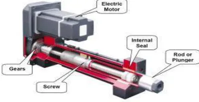
1. ELECTRIC ACTUATOR
An electric actuator is powered by a motor that converts electrical energy into mechanical torque. The electrical energy is used to actuate equipment such as multi-turn valves. It is one of the cleanest and most readily available forms of actuator because it does not involve oil.
2. HYDRAULIC ACTUATOR
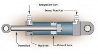
A hydraulic actuator is shown in Figure 1. It consists of a cylinder or fluid motor that uses hydraulic power to facilitate mechanical operation. The mechanical motion gives an output in terms of linear, rotary or oscillatory motion. Because liquids are nearly impossible to compress, a hydraulic actuator can exert considerable force. The drawback of this approach is its limited acceleration. The hydraulic cylinder consists of a hollow cylindrical tube along which a piston can slide. The term single acting is used when the fluid pressure is applied to just one side of the piston. The piston can move in only one direction, a spring being frequently used to give the piston a return stroke. The term double acting is used when pressure is applied on each side of the piston; any difference in pressure between the two side of the piston moves the piston to one side or the other.
Figure 1: Hydraulic actuator
3. PNEUMATIC ACTUATOR
Figure 2: Pneumatic Actuator
Pneumatic energy is desirable for main engine controls because it can quickly respond in starting and stopping as the power source does not need to be stored in reserve for operation. Pneumatic actuators enable large forces to be produced from relatively small pressure changes. These forces are often used with valves to move diaphragms to affect the flow of liquid through the valve. It is responsible for converting pressure into force.
4. THERMAL OR MAGNETIC ACTUATOR
Actuators which can be actuated by applying thermal or magnetic energy have been used in commercial applications. They tend to be compact, lightweight, economical and with high power density.
These actuators use shape memory materials (SMMs), such as shape memory alloys (SMAs) or magnetic shape-memory alloys (MSMAs). Some popular manufacturers of these devices are Finnish Modti Inc., American Dynalloy and Rotork.The Thermal or magnetic actuator is shown in Figure 3.
Figure 3: Thermal or Magnetic Actuator
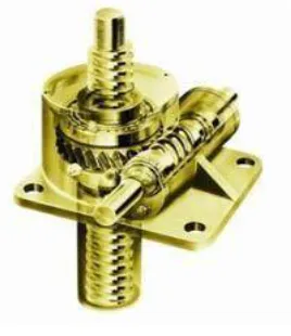
5. MECHANICAL ACTUATOR
Figure 4: Mechanical Actuator
III. FEATURES OF MASONEILAN 87/88 ACTUATOR
Masoneilan Type 87 direct-acting and Type 88 reverse acting pneumatic spring diaphragm actuators are designed to provide high performance. Product features include:
1. Field Reversible
Allows air action change in the field without any additional parts.
2. Multiple Spring Design
Four standard spring ranges achievable by varying spring quantity and placement.
3. Heavy One-Piece Yoke
Provides maximum strength and support for reliable performance.
4. Diaphragm Cases
Pressed steel upper and lower cases combine lightness, high mechanical strength, and protection in the event of over pressurization.
5. Application Flexibility
Five different sizes provide a broad range of stroke and thrust capabilities.
6. Reliability
Molded elastomer diaphragm with fabric insert provides strength, long life and high sensitivity.
7. Linearity
The molded rolling diaphragm and deep cases minimize area change, resulting in a linear relationship between travel and air pressure.
8. Key Accessories
IV. PROBLEM IDENTIFICATION
While observing the assembly procedure of MASONEILAN 87/88 type actuator in BARANI HYDRAULICS INDIA Pvt. Ltd. We have found that scratches were formed in the stems due to improper holding in fixture.
The manually operated collet type fixture is the reason for scratches in the stem. It does not have sufficient force to hold the stem, while giving maximum torque to tighten the diaphragm the stem starts to rotate, which causes scratches in the stem.
Scratches in the stem leads to iteration of sealing elements this causes leak during the working of the actuators. Sometimes it goes beyond the control. And also it takes more time for sub assembly. This causes delay in production.
The stem is a major part of an actuators. It consists linear motion(up & down) and it is controlled by pneumatic system. Stem is used for opening and closing operation.
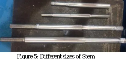
There are different sizes of stems used for different types of actuator sizes so it requires different collets, as shown in Figure 5.
Figure 5: Different sizes of Stem
The Figure 6 shows the scratches in stem while assembly. The stem is surround by the housing in which several Split collet clamping jaws, each with one side lining and one brake lining are assembled. When pressure is applied to the plunger the clamping jaws are held in a raised position so that the rod can move freely the springs are compressed in this position.
Figure 6: Scratches in stem
V. SOLUTION
To over come this problem the split collet type clamping fixture can be used. This will reduce the damage of stem and also it will withstand the high torque. This Split collet type clamping fixture release by applying hydraulic or pneumatic pressure and clamp at pressure loss. The kinetic energy of the falling mass is then used to generate the holding force
VI. FUNCTION
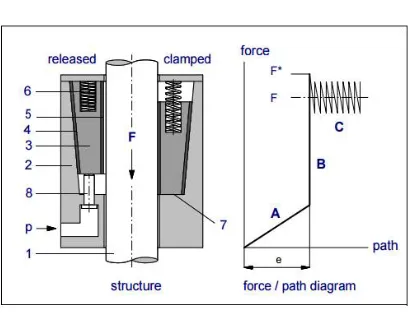
Figure 7: Design principle
The clamping jaws only cover small distance until the radial play is eliminated and an equilibrium between the spring forces and the force generated on the slide linings and break linings is achieved. At this point the stem is hold by the clamping jaws.
VII. ASSEMBLY PROCEDURE
The assembly procedure of 87/88 diaphragm type actuator is given in detail below. This involves three stages to complete total assembly. They are given with detailed description below.
Assembly involves in three stages
• Sub assembly • Main assembly • Leak test
1. SUB ASSEMBLY
The sub assembly part of the actuator assembly consists of two stages
• Stem assembly • Lowercase assembly
2. STEM ASSEMBLY
The Split collet type clamping fixture is used in the stem assembly process. Here all the child parts are assembled. For this purpose, manually controlled fixture is used formerly this makes scratches in the stem which in turn gets total loss of an actuator.
3. LOWER CASE ASSEMBLY
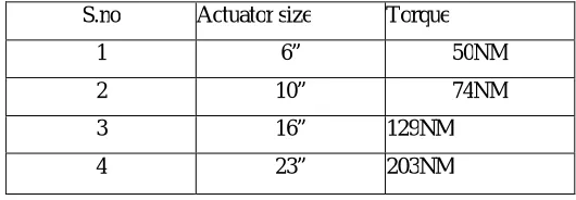
In lower case assembly, yoke and lower case are assembled. After that, the stem and diaphragm are placed inside the lower case. In this sub assembly for different sizes of actuator stems different range of torque is given the torque range details are given below in the Table 1.
Table 1: TORQUE ANALYSIS TABLE
S.no Actuator size Torque
1 6” 50NM
2 10” 74NM
3 16” 129NM
4 23” 203NM
Figure 8: Currently used fixture
Instead the Split collet type clamping fixture is suggested for the easier handling and high holding torque, so that the scratches can be avoided.
VIII. PHOTOGRAPHY
Figure 10: Cross sectional view of Split collet type fixture
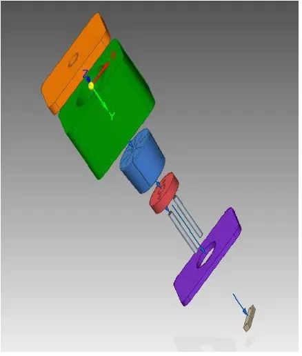
Figure 11: Exploded View of Split collet type fixture
IX. CONCLUSION
By using this split collet type fixture we can reduce the damage of stem. This split collet type fixture will withstand the high torque. It also avoid slipping of stem from the fixture due to its high holding force. This Split collet type clamping fixture release by applying hydraulic or pneumatic pressure and clamp at pressure loss. This is used to prevent the stem from scratches. Handling issues are made easier while compared with the currently using manually controlled fixture. The plungers are used in order to lift the collet for holding purpose. The plunger base helps to hold the plunger which helps in placing the plunger in a perfect position which in turn helps for proper movement of plunger for lifting the collet.
REFERENCES
(1) White, Lynn Jr. (1966). Medieval Technology and Social Change. New York: Oxford Univ. Press. ISBN 0-19-500266-0., p.126-127. (2) Usher, Abbot Payson (1988). A History of Mechanical Inventions. Courier Dover. ISBN 0-486-25593-X., p.305.
(3) Henkenius, Merle (2006). Ultimate Guide to Plumbing. Creative Homeowner Press. p. 216. ISBN 1580113117. (4) Lou Manfredini (2004). Lou Manfredini's House Smarts. Random House. p. 28. ISBN 0345449894. (5) Colvin, Fred H.; Haas, Lucian L. (1938).