ISSN(Online): 2319-8753 ISSN (Print): 2347-6710
I
nternational
J
ournal of
I
nnovative
R
esearch in
S
cience,
E
ngineering and
T
echnology
(A High Impact Factor & UGC Approved Journal)
Website: www.ijirset.com
Vol. 6, Issue 9, September 2017
Current Source Converter Based Offshore
Wind Farm with Medium Frequency
Transformer Using Fuzzy Logic Controller
K.Chandana 1, M.Murali krishna 2
P.G. Student, Department of Electrical and Electronics Engineering, Sri Padmavathi Mahila Visvavidyalayam, , Tirupati, India1
Associate Professor, Department of Electrical and Electronics Engineering, Sri Padmavathi Mahila Visvavidyalayam, , Tirupati, India2
ABSTRACT: Offshore wind farms with series structures are promising design of the fact that costly and costly offshore substations can be reduced. In this present work, a medium-frequency transformer (MFT) - based wind energy conversion is proposed for such offshore wind farm based on current source converter. The present arrangement comprises of a medium-voltage permanent magnet synchronous generator that is associated with a minimal effort inactive rectifier, a MFT-based cascaded converter, and a current source inverter . Aside from satisfying conventional control targets , this work attempts to guarantee uniformly conveyed power and voltage sharing among the constituent modules given the fell structure of the MFT-based converter .This paper completely examines the normal for decoupling between the voltage control adjusting of the secluded converter and the other control targets. At long last, both exploratory outcomes are given to mirror the execution of the proposed framework.
KEYWORDS: Current source converter, permanent magnet synchronous generator, wind energy conversion system, medium-frequency transformer, cascaded DC-DC converter.
I.INTRODUCTION
Among all existing renewable energy sources, wind energy(onshore and offshore) has progressively turned into a standard one[1]. Dissimilar to inland applications, introduced offshore wind power capacity is just 2% of the aggregate limit starting at 2012 [2]. In any case, an expanding pattern is gauge as a result of [3] (a) wind assets are significant. (b) Offshore wind speed is frequently fundamentally higher and steadier than that onshore. (c) The ecological impact (capable of being heard clamor and visual impact) is the limited in offshore applications.
ISSN(Online): 2319-8753 ISSN (Print): 2347-6710
I
nternational
J
ournal of
I
nnovative
R
esearch in
S
cience,
E
ngineering and
T
echnology
(A High Impact Factor & UGC Approved Journal)
Website: www.ijirset.com
Vol. 6, Issue 9, September 2017
MV-based power converters, which are pivotal parts in WECS, can be classified into voltage source converters (VSCs) and current source converters (CSCs). From one viewpoint, VSC-based WECS overwhelms offshore wind farm applications.
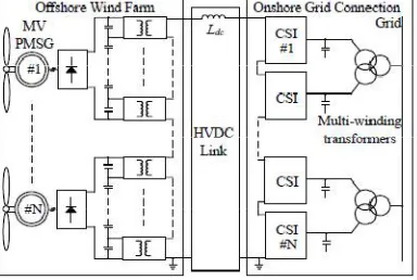
In the present work, a medium frequency transformer (MFT) - based WECS is proposed for arrangement associated CSC-based offshore wind ranches (Fig. 1). The setup comprises of a MV PMSG that is associated with a minimal effort three-stage diode rectifier, a particular MFT-based converter, and an inland CSI associated with the lattice through a multi-winding transformer. The present paper for the most part concentrates on two of the real issues in a offshore wind farm. One is to dispose of the cumbersome and expensive offshore substation, and the other is to take out the massive and overwhelming low-frequency transformer which is regularly introduced in the nacelle or inside the tower of the wind turbine.
II. CONFIGURATION OF THE PROPOSED WECS
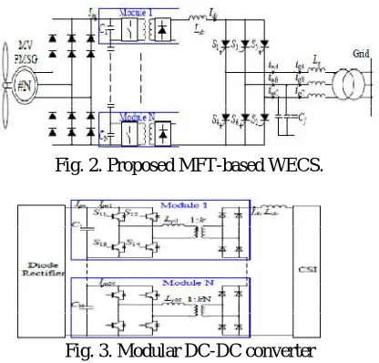
Fig. 1 demonstrates the general structure of the CSC-based offshore wind cultivate. N quantities of the proposed MV PMSG-based WECSs are associated in arrangement with one basic dc-connect inductor . The coastal CSIs are associated with the matrix through multi-winding transformers. Fig. 2 delineates the topology of the proposed MFT-based WECS; the design comprises of a MV PMSG, a three-stage diode rectifier, a secluded MFT-MFT-based converter, and a CSI that is associated with the network through a transformer. is the output capacitor and speaks to the framework side inductance. Fig. 3 represents the definite topology for the particular MFT-based converter, in which N quantities of voltage-bolstered, current-output converters (without a output capacitor channel) are associated in arrangement, at that point specifically associated with the dc-interface inductor . CN (N = 1, 2 … , N) is input capacitor of every module in the fell converter.
The front-end converter ,and the latent rectifier shows the upsides of unwavering quality, ease, being little and light, and having a more straightforward generator-side control than a PWM converter dosage. Moreover, the synchronous inductance of a PMSG is for the most part over 0.4 for every unit (pu) for high-control, low-speed wind applications, which further helps to mitigate the torque ripple.
low-frequency three-stage transformer is utilized, the proposed secluded MFTs-based arrangement is focal points in terms of higher power thickness, little impression and weight (which is significantly more vital for offshore application). In expansion, by the proposed
Fig. 1. Proposed configuration of CSC-based offshore wind farm
ISSN(Online): 2319-8753 ISSN (Print): 2347-6710
I
nternational
J
ournal of
I
nnovative
R
esearch in
S
cience,
E
ngineering and
T
echnology
(A High Impact Factor & UGC Approved Journal)
Website: www.ijirset.com
Vol. 6, Issue 9, September 2017
arrangement associated CSC-based offshore wind cultivate in a past think about. By differentiate, the present work concentrates on the control plan of the single MV PMSG-based WECS (Fig. 2).
Fig. 2. Proposed MFT-based WECS.
Fig. 3. Modular DC-DC converter
III.ANALYSIS OF THE MODULAR CONVERTER
The particular converter (Fig. 3) assumes essential parts in the proposed WECS. To begin with, it is helpful for accomplishing both MPPT and, lattice side control . Second, MFT is utilized on the grounds that of the generator protection issue which has been examined in the past area, along these lines not rehashed here. Rather than utilizing cumbersome low-frequency transformers, MFTs are utilized given their points of interest of high power thickness and simple offshore development. Expanding working frequency brings about a huge decrease in size and weight of the transformer. In any case, in the application MV Megawatts-level WECS, a few difficulties ought to be considered: (a) Losses and warm plan. A critical test will be acquainted with warm what's more, cooling framework outline because of the blend of little size furthermore, high misfortunes as expanding operation frequency; (b) challenge originating from the protection outline of high-control MFT. In uses of arrangement associated wind cultivate, the greatest potential the transformer must withstand is the full transmission level.
A.Determination of the number of cells
The base required number of cells for the proposed arrangement relies upon: (a) input dc voltage, (b) the voltage rating of the chosen protected entryway bipolar transistor (IGBT), what's more, (c) the picked cell voltage. The appraised input dc voltage is roughly 5000 V for a 4000 V PMSG-based framework. 1700 V IGBT is chosen since it is the most appropriate exchanging gadget regarding cost, voltage use, and disappointment in time rate for MV applications. Given a cell voltage of 1000 V, five cells (without excess) must be associated in arrangement at both the info and the output. A converter with six cells can likewise be decided for repetition (N+1); in any case, this work considers a measured converter with five cells.
B.MFT
ISSN(Online): 2319-8753 ISSN (Print): 2347-6710
I
nternational
J
ournal of
I
nnovative
R
esearch in
S
cience,
E
ngineering and
T
echnology
(A High Impact Factor & UGC Approved Journal)
Website: www.ijirset.com
Vol. 6, Issue 9, September 2017
A. Operation Principle
One preferred standpoint of a secluded converter is its control conspire can be streamlined that every single constituent module share the same control. It implies the drive signals for S11, S21 … S51 are same (Fig. 3) as are different switches. Here, we take Module 1 as an case to represent the operation rule. The ordinary stage moved tweak conspire is utilized where all the switches work with settled half obligation cycle, while the period of the second leg is moved to exchange the power. The consistent state waveform is appeared in Fig. 4 where the dead time between switches in a similar leg is not appeared. S11, S12, S13, and S14 are the comparing drive signals; Idc and ip1 are dc-link current also, transformer essential currents (Fig. 3), separately; Vo1 is the output voltage. The comparing operation states are appeared in Fig. 5. Before t0, switches S11 and S14 are on, thus are D11 and D14 (Fig. 5 [a]). The transformer essential/optional streams ip1/is1 and the output voltage Vo1 are currently kept at 1 pu, also, the power is exchanged to the heap. t0 < t < t1: At time t0, S14 is off, essential current ip1 commutates from S14 to the parallel diode of S12 amid the dead time; in this way, S12 is turn on with zero voltage exchanging (ZVS). Amid this period, streams ip1/is1 are somewhat diminishing to under 1 pu, while the dc-connect current Idc is controlled to keep up at 1 pu by the CSI; accordingly, D12 and D13 are turn on (D11 and D14 are remaining on). The output voltage Vo1 is presently remaining at 0 pu, and no power is exchanged (Fig. 5 [b]). t1 < t < t2: At time t1, S11 is off, and as same as that in the past period, S13 is turn on with ZVS. Streams ip1/is1 is currently diminishing forcefully with the incline dictated by the information voltage and the estimation of the spillage inductor. Amid this period, D11, D12, D13 and D14 are as yet kept on and no power is exchanged (Fig. 5 [c]). t2 < t < t3: At time t2, Streams ip1/is1 is diminishing to –1 pu; in the interim, D11 and D14 are off, while D12 and D13 are continued. The output voltage Vo1 is currently remaining at 1 pu, and the power is exchanged to the stack (Fig. 5 [d]). t3 < t < t4: At time t3, S12 is off; S14 is turn on with zero voltage exchanging (ZVS). The operation standard is same as that amid t0 < t < t1. In this way is not rehashed here (Fig. 5 [e]). After t4, same operation cycle rehashes as appeared in Fig. 4.
IV.CONTROL SCHEME OF THE PROPOSED WECS
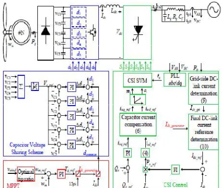
The control conspire is created as per coordinate prerequisites of the WECS itself and the attributes of the proposed design. General control targets are recognized as: (1) MPPT in the full operation; (2) input capacitor voltage sharing of the particular converter; (3) least dc-interface current control; and (4) receptive power control. Fig. 6 shows the general control plan of the proposed WECS, where MPPT what's more, input capacitor voltage adjust control are accomplished with the generator-side converter while least dc-interface current what's more, responsive power control are controlled by the network side CSI. Every one of the images utilized as a part of the rest of this paper relate to those appeared in this figure.
A. Generator-side control
ISSN(Online): 2319-8753 ISSN (Print): 2347-6710
I
nternational
J
ournal of
I
nnovative
R
esearch in
S
cience,
E
ngineering and
T
echnology
(A High Impact Factor & UGC Approved Journal)
Website: www.ijirset.com
Vol. 6, Issue 9, September 2017
Fig. 4. Steady State waveform of Module 1.
Fig. 5. Operation States of Module 1.
The controller output is indicated by torque reference Tg_ref of the generator, which is relative to the comparing generator current Idc_generator. P and are the shaft matches and flux of the PMSG (Fig. 6). The required obligation
cycle dcommon for the dc-dc converter is acquired by contrasting Idc_generator and DC-connect current Idc. MPPT is
accomplished after applying the basic obligation cycle dcommon to the dc-dc converter.
ISSN(Online): 2319-8753 ISSN (Print): 2347-6710
I
nternational
J
ournal of
I
nnovative
R
esearch in
S
cience,
E
ngineering and
T
echnology
(A High Impact Factor & UGC Approved Journal)
Website: www.ijirset.com
Vol. 6, Issue 9, September 2017
Fig. 7. Ideally simplified configuration of the proposed WECS
Along these lines, the identical circuit of the MFT-based fell dc-dc converter is determined appeared in Fig. 8, where input voltage Vin is the output voltage of the rectifier. Iin is the info current of the MFT-based fell dc-dc converter the
dc-interface current; Idc is spoken to by a steady current source. In this exploration, VIN and Idc are variable as indicated
by various wind rates and consistent at a given speed.
Fig. 8. Equivalent circuit of the MFT-based cascaded DC-DC converter
The MFT-based converter is associated in arrangement at the information also, the output. Such converters shares information and output streams Iin and Idc, individually. Through power protection, the accompanying is gotten:
= = = = = =
. (1) = = =
Where VC1, VC2 … and VC5, and Vo1, Vo2 … and Vo5 are the harmony estimations of the info and output voltages of the constituent modules, separately. Pin1, Pin2 … and Pin5, and Po1, Po2 … and Po5 are the info and output energy of every module, separately. Accepting that the info capacitor voltage is adjusted.
= = =………. = (2)
At that point, output voltage is consequently accomplished. Moreover, add up to power can be conveyed equally among every one of the modules. Consequently, we require just concentrate on input capacitor voltage sharing to accomplish both info/output voltages and power partaking in the MFT-based fell dc-dc converter. The constituent modules of the dc-dc converter basically have a place with a Buck converter with the accompanying information/output attributes:
ISSN(Online): 2319-8753 ISSN (Print): 2347-6710
I
nternational
J
ournal of
I
nnovative
R
esearch in
S
cience,
E
ngineering and
T
echnology
(A High Impact Factor & UGC Approved Journal)
Website: www.ijirset.com
Vol. 6, Issue 9, September 2017
. (3) =f( )
Where d1, d2 … , and d5 are the obligation cycles and f (d1), f (d1) … , what's more, f (d5) are the voltage increases of every converter under relentless state.
Grid-side control:
The significant control goals for the lattice side CSI are dc-interface present and responsive power control. Dissimilar to in VSC-based WECS where dc-interface voltage is regularly controlled at a Consistent esteem, the dc-connect current in CSC-based WECS is arable as indicated by various levels of caught energy to limit misfortune. It is dictated by both the generator and the network side to accomplish (an) all the control destinations and (b) a least WECS misfortune.
As appeared in Fig. 6, dc-interface current control modifies the caught wind control while receptive power control is executed to direct responsive power as per the network codes. The Grid-voltage stage bolted circle (PLL) is utilized to produce a commotion free synchronous angle and angular frequency given the adjusted synchronous angle, the dynamic what's more, receptive power (Ps, Qs) can be controlled autonomously by the accompanying:
=1.5 (4)
Q =-1.5V (5) where Vsd and Vsq and isd and isq are the d- and q-axis components of the grid voltage and injected current. The reference current of the CSI iwd_ref and iwq_ref can be derived with the following,
_ = _ + = _ - (6) _ = _ + = _ +
Where isd_ref and isq_ref are the references of the d-and q-pivot segments of the infused network current. icd, icq and Vcd, Vcq are d-and q-pivot parts of the capacitor current and the voltage; these factors can be communicated as takes after:
= + -
= + (7) Where Lg and Rg speak to the matrix side line inductance and resistance, individually. Without misfortune thought of
the converter, the caught wind control is equivalent to the matrix infused control
= (8)
With considering the most extreme tweak record as mi = 1, the base dc-interface current Idc_grid controlled by the grid side CSI can be determined in light of (4)–(8):
_ = 1− − (
_
) + 1− + + ( )
ISSN(Online): 2319-8753 ISSN (Print): 2347-6710
I
nternational
J
ournal of
I
nnovative
R
esearch in
S
cience,
E
ngineering and
T
echnology
(A High Impact Factor & UGC Approved Journal)
Website: www.ijirset.com
Vol. 6, Issue 9, September 2017
Therefore, the final minimum dc-link current reference Idc_ref, is expressed as:
_ =max( _ , _ ) (10)
Where Idc_generator is the base dc-interface current dictated by the generator-side, as showed in Fig. 6.
V.FUZZY LOGIC CONTROLLER
Fuzzy logic control is a non-mathematical decision algorithm that is based on an operator’s experience. This type of control strategy is suited well for nonlinear Systems. Fig.9 shows the structure of the fuzzy logic control algorithm.
Fig.9. Structure of Fuzzy Logic Controller.
A. Fuzzifier Fuzzy logic uses linguistic variables instead of numerical variables. In a closed loop control system, the error (e) between the reference voltage and the output voltage and the rate of change of error (dele) can be labeled as zero (ZE), positive small (PS), negative small (NS), etc. In the real world, measured quantities are real numbers (crisp). The process of converting a numerical variable (real number) into alinguistic label (fuzzy number) is called fuzzification. Fig.7 shows the membership functions that are used\ to fuzzify the inputs.
.
INPUT1
ISSN(Online): 2319-8753 ISSN (Print): 2347-6710
I
nternational
J
ournal of
I
nnovative
R
esearch in
S
cience,
E
ngineering and
T
echnology
(A High Impact Factor & UGC Approved Journal)
Website: www.ijirset.com
Vol. 6, Issue 9, September 2017
Fig.10. Membership Functions
The Fuzzy Logic Controller the inputs are mapped into these membership functions and a degree of membership is found for how much the input belongs to that particular linguistic label. The membership can take on a value from zero to unity for each of the linguistic labels. The waveforms are evenly distributed about the range of operation of the variables. For each of the input and output variables, the following seven linguistic labels are assigned to the membership functions: NL = Negative Large NM = Negative Medium NS = Negative Small ZE = Zero PS = Positive Small PM = Positive Medium PL = Positive Large Once the membership is found for each of the linguistic labels, an intelligent decision can be made to what the output should be. This decision process is called inference.
The rules of a fuzzy logic controller give the controller its intelligence, assuming the rules are developed by a person who has a experience with the system to be controlled. A programmer with more experience with the system will create a better controller. From this desired goal, rules are made for every combination of voltage and rate of change of voltage on what the output should be in order to stabilize. It is convenient when dealing with a large number of combinations of inputs, to put the rules in the form of a rule table.
Fig.11. Fuzzy Logic Rule Table.
VI. SIMULATION
The proposed control scheme is verified by using MATLAB/SIMULINK software.
SIMULATION RESULTS USING PI CONTROLLER:
Case1:
The proposed configuration can be verified under condition of with and without voltage balancing control.
Before t = 2 s, the system operates in steady state with voltage balance control. At t = 2 s, the voltage balance control scheme is deactivated (all five modules operate under the common duty cycle dcommon [Fig. 6]). At t = 2.5 s, the voltage balance control scheme is reactivated and input capacitor voltages quickly converge to nominal values.
ISSN(Online): 2319-8753 ISSN (Print): 2347-6710
I
nternational
J
ournal of
I
nnovative
R
esearch in
S
cience,
E
ngineering and
T
echnology
(A High Impact Factor & UGC Approved Journal)
Website: www.ijirset.com
Vol. 6, Issue 9, September 2017
Reactive power (Qs)
(VC1, VC2, VC3, VC4, and VC5)
Dc-link current Idc
Case2:The proposed can be verified under condition of step change in wind speed. wind speed is purposely set to step down and up from 12 m/s (1 pu) to 10 m/s (0.833 pu) at t = 2 s and from 10 m/s (0.833 pu) to 12 m/s (1 pu) at t = 4 s, respectively.
ISSN(Online): 2319-8753 ISSN (Print): 2347-6710
I
nternational
J
ournal of
I
nnovative
R
esearch in
S
cience,
E
ngineering and
T
echnology
(A High Impact Factor & UGC Approved Journal)
Website: www.ijirset.com
Vol. 6, Issue 9, September 2017
Reactive power (Qs)
Reference and real speed of the PMSG (wg _ref, g)
Reference and real speed of the PMSG (wg_ref, g); Dc-link current (Idc, Idc_ref);
(VC1, VC2, VC3, VC4, and VC5).
Case3:
ISSN(Online): 2319-8753 ISSN (Print): 2347-6710
I
nternational
J
ournal of
I
nnovative
R
esearch in
S
cience,
E
ngineering and
T
echnology
(A High Impact Factor & UGC Approved Journal)
Website: www.ijirset.com
Vol. 6, Issue 9, September 2017
Active power (Ps)
Reactive power (Qs)
(VC1, VC2, VC3, VC4, and VC5).
Dc-link current (Idc)
SIMULATION RESULTS USING FUZZY CONTROLLER: Case1:
ISSN(Online): 2319-8753 ISSN (Print): 2347-6710
I
nternational
J
ournal of
I
nnovative
R
esearch in
S
cience,
E
ngineering and
T
echnology
(A High Impact Factor & UGC Approved Journal)
Website: www.ijirset.com
Vol. 6, Issue 9, September 2017
= 2.5 s, the voltage balance control scheme is reactivated and input capacitor voltages quickly converge to nominal values.
Real power(Ps)
Reactive power (Qs)
(VC1, VC2, VC3, VC4, and VC5)
ISSN(Online): 2319-8753 ISSN (Print): 2347-6710
I
nternational
J
ournal of
I
nnovative
R
esearch in
S
cience,
E
ngineering and
T
echnology
(A High Impact Factor & UGC Approved Journal)
Website: www.ijirset.com
Vol. 6, Issue 9, September 2017
Case2:The proposed can be verified under condition of step change in wind speed. wind speed is purposely set to step down and up from 12 m/s (1 pu) to 10 m/s (0.833 pu) at t = 2 s and from 10 m/s (0.833 pu) to 12 m/s (1 pu) at t = 4 s, respectively.
Active power (Ps)
Reactive power (Qs)
Reference and real speed of the PMSG (wg_ref, g);
ISSN(Online): 2319-8753 ISSN (Print): 2347-6710
I
nternational
J
ournal of
I
nnovative
R
esearch in
S
cience,
E
ngineering and
T
echnology
(A High Impact Factor & UGC Approved Journal)
Website: www.ijirset.com
Vol. 6, Issue 9, September 2017
(VC1, VC2, VC3, VC4, and VC5).
Case3:The proposed can be verified under condition of reactive power control. Reactive power Qs is injected into the grid according to grid codes [3] with 330 kVA (0.33 pu) between 2 and 3 s, –330 kVA (–0.33 pu) between 4 and 5 s, respectively.
Active power (Ps)
Reactive power (Qs)
ISSN(Online): 2319-8753 ISSN (Print): 2347-6710
I
nternational
J
ournal of
I
nnovative
R
esearch in
S
cience,
E
ngineering and
T
echnology
(A High Impact Factor & UGC Approved Journal)
Website: www.ijirset.com
Vol. 6, Issue 9, September 2017
Dc-link current (Idc)
VII. CONCLUSION
In this paper, an MFT-based WECS is proposed for CSC-based offshore wind farms. The proposed configuration is composed of an MV PMSG, a passive rectifier, a modular MFT-based converter, and a CSI.the proposed method is analyzed using MATLAB/SIMULINK software It is characterized by (a) no offshore substation; (b) high power density due to the adaption of a modular MFTs instead of a low-frequency transformer; (c) high reliability and flexibility due to the use of a modular converter; and (e) all the advantages of a CSC. From the above comparison of simulation results it is clear that fuzzy controller gives fast response tan PI controller. Fuzzy controller has less rising and settling time then conventional PI controller and has better dynamic and steady state properties .
REFERENCES
[1] Global Wind Energy Outlook 2010, Global Wind Energy Council, London, U.K., 2010.
[2] The European Wind Energy Association (EWEA), Offshore Wind, 2014, accessed on Aug. 2014. [Online]. Available: http://www.ewea.org. [3] B. Wu, Y. Lang, N. Zargari and S. Kouro, Power Conversion and Control of Wind Energy Systems. Wiley-IEEE Press, 2011.
[4] P. Bresesti, W. Kling, R. Hendriks, and R. Vailati, ‘‘HVDC connection of offshore wind farms to the transmission system,’’ IEEE Trans. Energy Convers., vol. 22, no. 1, pp. 37–43, Mar. 2007.
[5] N. Flourentzou, V. Agelidis, andG. Demetriades, ‘‘VSC-based HVDC power transmission systems: An overview,’’ IEEE Trans. Power Electron., vol. 24, no. 3, pp. 592–602, Mar. 2009.
[6] C. Meyer, M. Hoing, A. Peterson, and R. De Doncker, ‘‘Control and design of DC grids for offshore wind farms,’’ IEEE Trans. Ind. Appl., vol. 43, no. 6, pp. 1475–1482, Nov. 2007.
[7] E. Veilleux and P. Lehn, ‘‘Interconnection of direct-drive wind turbines using a series-connected DC grid,’’ IEEE Trans. Sustain. Energy, vol. 5, no. 1, pp. 139–147, Jan. 2014.
[8] Venkata Yaramasu, Bin Wu, Paresh C. Sen., “High-Power Wind Energy Conversion Systems State-of-the-Art and Emerging Technologies,” Proceedings of IEEE. DOI: 10.1109/JPROC.2014.2378692.
[9] Z. Zhu and J. Hu, ‘‘Electrical machines and power-electronic systems for high-power wind energy generation applications: Part IIVPower electronics and control systems,’’ COMPEL: Int. J. Computat. Math. Elect. Electron. Eng., vol. 32, no. 1, pp. 34–71, 2013.