ABSTRACT
MATHEW KALLUMKAL, GEORGY. A Micro-cloud Model for Adaptable High Performance Computing. (Under the direction of Dr. Mladen Vouk.)
High performance computing (HPC) and High-performance data (HPD) capabilities
are now becoming the norm for advancing science through modeling simulations and data
analytics. Often a serious limitation is internal and inter-computational node
commu-nication topology. They tend to be fixed. This basically means that applications and
problems need to map onto these specialized architectures. This is expensive, takes a
long time, and poses a challenge for rapidly rising demands for computation and data
analytics. Instead, it may be a much better solution to virtualize the topology, re-arrange
the nodes, and offer applications architectures which are dynamically customized for the
computation and data analysis problem in hand. This, for example, is a reason why new
FPGA accelerated as well as data-flow oriented HPC platforms are gaining interest.
In this project we are investigating a software-based solution to the problem using an
open source cloud technology called VCL (Virtual Computing Laboratory) in combination
with an open source solution called KittyHawk. As a proof of concept, we have created a
soft-version of a reconfigurable architecture residing in a supercomputing environment
(specifically IBM BlueGene/P or BG/P). Solution conforms to the Department of Energy
secure access standards. Configuration is managed using a root-less version of VCL code
and IBM Kittyhawk running on BG/P. Pilot is implemented on the Argonne National
Laboratory (ANL) Surveyor BG/P. This implements a distributed cloud computing model
we call VCL Micro-cloud, with KittyHawk as its provisioning engine where users are
able to request individual BlueGene nodes under topology of their choosing and design
Micro-cloud has a management node which controls and provisions other nodes in the
cluster and executes the requested application on them. A user who wants to have a
customized Micro-cloud needs to make a reservation of the image environment in VCL
and then request a template which then will be configured as a Micro-cloud on BG/P.
Results indicate that Micro-clouds of different configurations can be easily constructed.
Network interfaces between the nodes in the cluster are configured based on templates.
We describe the technology, illustrate how to setup such an environment, and we discuss
© Copyright 2013 by Georgy Mathew Kallumkal
A Micro-cloud Model for Adaptable High Performance Computing
by
Georgy Mathew Kallumkal
A thesis submitted to the Graduate Faculty of North Carolina State University
in partial fulfillment of the requirements for the Degree of
Master of Science
Computer Networking
Raleigh, North Carolina
2013
APPROVED BY:
Dr. Patrick Dreher Dr. George Rouskas
Dr. David Thuente Dr. Mladen Vouk
DEDICATION
BIOGRAPHY
Georgy Mathew was born in Mumbai, India. He did his primary and secondary schooling
from St. Francis D’Assisi High School, Mumbai, India. He received his Bachelors degree
in Electronics and Tele-communication from University of Mumbai in May 2011. He
joined North Carolina State University in Fall 2011 for pursuing Masters in Computer
ACKNOWLEDGEMENTS
I would express my sincere gratitude to my advisers, Dr. Mladen Vouk and Dr. Patrick
Dreher for their invaluable guidance in performing research, writing this thesis, and
throughout the course of my graduate studies. It is because of their continuous support
and assistance I was able to finish this work successfully. I would like to sincerely thank
Dr. George Rouskas and Dr. David Thuente for their kind consent to serve on my thesis
committee. I am obliged to Dr. Marta Garcia Martinez, Assistant Computational Scientist
at the ALCF for providing us all help and assistance regarding the needs and requirements
of ACLF resources on this VCL-on-BG/P project. I am extremely thankful to William
Allock, ALCF Director of Operations for helping us to get the hardware configuration and
dedicated log-in server needed to conduct this project on the Surveyor BG/P machine.
I would like to take this opportunity to thank Prof. Jonathan Appavoo, distinguished
professor at Boston university one of the Kittyhawk developers, and his graduate student
Dan Schatzberg for providing us help and advice in porting the Kittyhawk utility at
ALCF. I would also like to thank Mr. Marhn Fullmer, manager of Netlabs at NCSU, for
his relentless technical support. I would like to take this opportunity to thank my research
group members Vikas Cheruku and Sai Rajesh, my friends Tom George, Leon Dmello,
Sanjana, Ishita Shinde, Ushma Thakker and Venisa for all their help and support.
This work was supported in part by NSF grant 0910767, the U.S. Army Research Office
(ARO) grant W911NF-08-1-0105 managed by NCSU Science of Security Initiative and
Science of Security Lablet, and IBM Share University Research and Fellowships program
funding, the Argonne Leadership Computing Facility at Argonne National Laboratory,
which is supported by the Office of Science of the U.S. Department of Energy under
TABLE OF CONTENTS
LIST OF TABLES . . . vii
LIST OF FIGURES . . . viii
Chapter 1 Introduction . . . 1
1.1 High Performance Computing . . . 3
1.2 HPC in the cloud . . . 5
1.3 FPGA based HPC and Data Flow Computing . . . 6
1.4 Network Interconnects on Supercomputing Hardware . . . 8
1.5 Motivation for Dynamic Topology Construction . . . 13
Chapter 2 Environment Used . . . 17
2.1 IBM BlueGene/P Architecture . . . 18
2.1.1 Node Model . . . 18
2.1.2 BlueGene Node Organization . . . 19
2.1.3 Interconnect Models . . . 22
2.2 KittyHawk . . . 23
2.2.1 KittyHawk Features . . . 23
2.2.2 KittyHawk Abstraction : Communication Domains . . . 24
2.3 Virtual Computing Lab (VCL) . . . 25
2.3.1 Services Provided by VCL . . . 25
2.3.2 VCL Architecture . . . 26
2.3.3 VCL reservation flow . . . 29
Chapter 3 System Design . . . 33
3.1 KittyHawk Design . . . 37
3.1.1 Workflow on BlueGene/P . . . 37
3.1.2 Configuring Modules . . . 41
3.2 VCL Desgin - Front End and Back End . . . 45
3.2.1 User Interface . . . 46
3.2.2 Database Modules . . . 54
3.2.3 Provisioning Modules . . . 57
Chapter 4 Implementation And System Flow . . . 60
4.1 Configuration and Implementation . . . 61
4.1.1 Module Installation and Configuration . . . 61
4.1.2 System Integration . . . 62
4.2.2 Loading BlueGene Environment . . . 69
4.2.3 Reserving Template / Micro-cloud . . . 71
Chapter 5 Experiments and Results . . . 74
5.1 Example 1 . . . 75
5.2 Example 2 . . . 79
Chapter 6 Conclusion and Future Work . . . 84
REFERENCES . . . 87
APPENDICES . . . 96
Appendix A Experiments and Results: Figures . . . 97
A.1 Example 1 . . . 97
A.2 Example 2 . . . 103
Appendix B Installation Manual . . . 108
B.1 User Manual for VCL Installation . . . 108
B.1.1 MySQL Installation and Configuration . . . 108
B.1.2 Perl Module Installation and VCL Configuration . . . 115
B.1.3 Web Interface Configuration . . . 121
B.2 Editing the Scripts . . . 124
LIST OF TABLES
Table 3.1 Mapping between nodes and custom networks . . . 48
Table 3.2 Using Continuations for Function calls . . . 50
Table 3.3 Table - anlbasenode : Details of ANL Management Node . . . 54
Table 3.4 Table - anljob : Details of ANL BlueGene Job . . . 55
Table 3.5 Table - anlloadlog : Details of status of Management Node Reservation 55 Table 3.6 Table - anlprovision : Provisioning Status of Template Reservation . . 55
Table 3.7 Table - anltempalte : Tempalte Configuration Details . . . 56
Table 3.8 Table - anlrequest : Reservation Request Details . . . 56
Table 3.9 Table - anltocomputer : ANL Computer Details . . . 56
LIST OF FIGURES
Figure 1.1 Interconnect Networks -Bus Topology . . . 9
Figure 1.2 Interconnect Networks - Crossbar switches . . . 10
Figure 1.3 Interconnect Networks - Ring Network . . . 11
Figure 1.4 Interconnect Networks - Multi-stage Networks . . . 11
Figure 1.5 Interconnect Networks - Mesh Networks . . . 12
Figure 1.6 Interconnect Networks - Torus Networks . . . 13
Figure 1.7 Scientific Workflow Topology example [98] . . . 14
Figure 2.1 BlueGene/P Compute Card Components . . . 19
Figure 2.2 BlueGene/P Node card components . . . 20
Figure 2.3 BlueGene/P Rack . . . 20
Figure 2.4 BlueGene/P Node Organisation . . . 21
Figure 2.5 VCL Architecture - referred from [32] . . . 27
Figure 2.6 VCL reservation Flow - Image Selection . . . 30
Figure 2.7 VCL reservation Flow - Create Reservation . . . 31
Figure 2.8 VCL reservation Flow - Backend Flow . . . 32
Figure 3.1 Design Flow Phase I . . . 35
Figure 3.2 Design Flow Phase II . . . 36
Figure 3.3 KittyHawk workflow on BlueGene/P . . . 42
Figure 3.4 Cluster Example on BlueGene/P . . . 43
Figure 3.5 VCL User Interface Tabs . . . 46
Figure 3.6 HPC-BGP Tab functions . . . 49
Figure 3.7 HPC-BGP Function 1 - Template Creation . . . 49
Figure 3.8 HPC-BGP Function 2 - Based node Reservation . . . 49
Figure 3.9 HPC-BGP Function 3 - Template Reservation . . . 50
Figure 3.10 HPC-BGP Function Flow 1 - Template Creation . . . 51
Figure 3.11 HPC-BGP Function Flow 2 - Base Node Reservation . . . 52
Figure 3.12 HPC-BGP Function Flow 3 - Template Reservation . . . 53
Figure 3.13 HPC-BGP Function Flow 4 - Delete Resources . . . 53
Figure 3.14 HPC-BGP Provisioning Module Flow . . . 58
Figure 4.1 Comuunication between Modules . . . 63
Figure 4.2 Micro-cloud with custom Network . . . 65
Figure 4.3 Virtual Computing Lab Homepage . . . 66
Figure 4.4 HPC-BGP Functions . . . 67
Figure 4.5 Cluster Node and Network Mapping . . . 68
Figure 4.6 Base Node Reservation linked to new BlueGene Job . . . 69
Figure 4.8 BluGene Environment Status . . . 71
Figure 4.9 Template Reservation . . . 72
Figure 5.1 Example 1: Control Flow Diagram . . . 76
Figure 5.2 Example 1: Data Flow Diagram . . . 77
Figure 5.3 Example 1: Node Topology Diagram . . . 78
Figure 5.4 Example 1: Result . . . 79
Figure 5.5 Example 2: Result . . . 81
Figure 5.6 Example 2: Control Flow Diagram . . . 82
Figure 5.7 Example 2: Data Flow Diagram . . . 83
Figure 5.8 Example 2: Node Topology Diagram . . . 83
Figure A.1 Example 1: Cluster Configuration . . . 98
Figure A.2 Example 1: Cluster Reservation Connect Details . . . 99
Figure A.3 Example 1: Node N1 Network interfaces . . . 100
Figure A.4 Example 1: Node N2 Network interfaces . . . 101
Figure A.5 Example 1: Node N3 Network interfaces . . . 102
Figure A.6 Example 2: Cluster Configuration Template . . . 103
Figure A.7 Example 2: Cluster Reservation Details . . . 104
Figure A.8 Example 2: Node N1 Ifconfig details . . . 105
Figure A.9 Example 2: Node N1 Interface ID’s . . . 105
Figure A.10 Example 2: Node N2 Interface Details . . . 106
CHAPTER
1
Introduction
In 1960 Seymour Cray introduced the first Supercomputer CDC 6600 [10] at Control Data
Corporation which provided very high computation peak performance. In early 1970’s
such high computations were required only in a few domains. But as Internet evolved
the demand to solve large scientific problems and data intensive applications significantly
increased. Today science and internet have grown to such an extent that huge amounts of
data needs to be processed daily. For example Facebook stores more than 30 petabytes
of data [9] daily which needs to be analyzed and filtered. High computational power is
largely needed in domains such as quantum physics, weather forecasting, climate research,
molecular modelling and physical simulations. Apart from these domains we are entering
into an age where the entire globe can be considered as a data field. Todays most of the
connected together using the Internet. Such an interconnected network is called Internet
of things [74]. There exists millions of such devices all over the world and these devices
process enormous amounts of data every minute. So we need systems that can process
large amount of data. These in turn would speed up the data analysis. Such huge amounts
of data which are generated daily from various firm and industries is termed as “Big Data”
[26]. Companies such as Google, Facebook, Twitter etc. which handle such large amount
of data daily depend heavily on such systems.
In order to solve these large data driven problems high performance supercomputers
are designed by some of the leading manufacturers such as Cray [11], IBM [22], Fujitsu
[16]. These systems can achieve peak speeds of 17.50 pflops, 16.32 pflops and 10.51 pflops
respectively. Such systems have nodes with multiple cores and memory. Large number
of nodes are aggregated together in racks which offer petaflop operation speed. These
nodes are tightly coupled and have fast network interconnects between processor units
which ensure high performance. There are many challenges associated in developing HPC
hardware, such as huge number of computers, developing an algorithm for scheduling and
executing data intensive applications, cost of hardware, cooling system etc. It becomes very
difficult to administer and maintain such high performance clusters and supercomputers.
Moreover, the underlying architecture on a supercomputer has a fixed network interconnect
topology between the nodes. There might be various workflows which, when mapped to
a custom topology, performs faster as opposed to a fixed topology.Authors in [12] list
various frameworks like Mapreduce [30] etc which can be used to process Big Data.
Cloud Computing technology provides on-demand services of various computing
resources which can be provisioned easily with minimum maintenance and administration
Data analytics. Yuichi et.al in [95] describes two methods which can be used for processing
big data in a cloud environment. It might be a good idea to construct a software layer
which maps the architecture to the problem and thus construct a custom topology based
on the application to be executed. The advantage of such a method is that we can have
the flexibility of constructing our own domain. Data can be distributed among various
nodes and will be processed based on a data flow model. In this chapter, we present the
current technologies that are used for high performance computations, how does HPC in
a cloud perform, how network interconnects on a supercomputing environment provide
much better performance than HPC clusters, how FPGA accelerated are used for HPC,
and the motivation behind creating a dynamic network based on Data Flow Computing.
1.1
High Performance Computing
High Performance Computing [23] is very essential for scientific workloads of various
Science Technology Engineering and Mathematics (STEM) projects which require very
high computing power and low network latency. Such high performances can be achieved
by running the applications on shared cluster environment [57] or on a supercomputing
hardware. Both these systems have their own advantages and disadvantages. One can argue
that shared clusters are loosely coupled and thus their performance will not be sufficient
in terms of bandwidth requirement specially when huge data chunks are considered. HPC
over the years has evolved from Cray machine in back 1970’s to cluster computing and
now supercomputers [54]. Cluster computing is technique in which local nodes are grouped
together using network connections and thus providing a shared resource [61]. There are
many manufacturers like Dell, HP and Intel who provide HPC solutions [13] [20] [24]
techniques for solving various scientific problems, analysis and modelling. In simple words,
it is about combining various systems together to produce high computing power to
cater the increasing demand for processing speed. The various scientific workloads can be
classified into following three categories, [64]
Large-scale tightly coupled systems : This category comprises of tightly coupled
HPC applications that require flexibility in computation.
Mid- Range or Loosely Coupled systems : These are workflows which can perform
using virtual clusters.
High-Throughput : Workflows that require high performance in post processing
analysis or calculations.
Since thousands of processors and gigabytes of memory are put together to produce
high computing powers, it is very expensive to run applications on such systems. In-spite
of advancements in chips, network interconnects and storage technologies the expense
incurred while using these platforms haven’t really come down so that a normal user can
use it from their laptop or desktop. In such a scenario, cluster computers are a useful
solution where distributed computing is performed between nodes either in a serial or
parallel fashion. It is important to note that all compute intensive problems cannot be
mapped to a cluster computing environment as the network connections or underlying
network topology might not be fast enough to support the requirements. It is interesting to
see the results that are obtained when these systems are integrated with cloud computing
technology [86] [50] [108]. Cloud computing provides an on-demand, pay as per use model
for shared resources. As mentioned earlier, if we can properly configure a cloud computing
HPC facility provided at North Carolina State University, where VCL Cloud Computing
Platform is used to provide HPC cluster access [34]. HPC applications which require
minimum I/O operations and communication between nodes in a cluster can be used via
a Cloud Computing environment. The next section presents the various cloud computing
solutions that are used to provide HPC facilities.
1.2
HPC in the cloud
Cloud Computing technology can be used as a management tool for HPC services. It
provides the flexibility in offering a user with IaaS, PaaS, SaaS etc [60] [87] [88] by sharing
computing resources. Based on the requirements resources can be easily provisioned and
deployed through the cloud. Various firms are looking at integrating HPC in the cloud
[21] [18] [39]. It is difficult for each and every individual to have the skill set and expertise
to develop algorithms for scientific workflows or big data analytics. In such situations
cloud solutions come in handy where the user can perform data intensive computations
through the cloud accessing the data in a distributed manner. Carlyle et.al [58] discuss
cost comparisons of doing scientific computations using a cloud computing in an HPC
environment. Amazon EC2 [3] added HPC capability to provide elastic compute clusters
for scientific and large scale computing in public cloud [2]. After Amazon added the
support for HPC services significant research has been conducted on the EC2 platform to
check computational performance [107] [66] [71] [75].
From these results, we can see that EC2 clusters are still lagging in terms of performance
as compared to tightly coupled HPC environments. They appear to be more suitable for
small scale HPC applications. Excellent network performance is a key criteria needed to
with EC2 cluster is that the performance is limited due to the network interconnects. An
improvement in the network interconnects will likely produce significant improvements
for compute intensive applications. There are other cloud solutions like Eucalyptus [14],
OpenStack [35], Hadoop MapReduce [30] [17] and Nimbus [33] which focus on loosely
coupled environments that can be used for scientific workflows which require less number
of I/O operations. Thus we can see that there is a need for research in this area to better
support the user demands for both HPC computing and data analytics.
1.3
FPGA based HPC and Data Flow Computing
From the above sections we have seen that traditional HPC environments offer very
good performance for compute-intensive applications. Field-Programmable Gate Arrays
(FPGAs) [15] were invented by Ross Freeman in 1984. Maxwell designed a FPGA
super-computer and investigated the concept of hardware acceleration for HPC [53]. FPGA
devices help to reconfigure High Performance Computing by optimizing the algorithm
for improved computation performance. In certain case studies [83], improvements in
operating speeds of 20-70 times faster were recorded. Various applications like fluid
flow, imaging, geoscience have also used FPGA accelerated hardware to obtain higher
performance. Today there are many systems [100] [69] [52] [55] [101] [93] today that use
FPGA accelerated hardware to obtain peak performances. As mentioned by Buell et.al in
[56] FPGA-based system follow the 10-90 rule (ie FPGA processors execute 10 percent of
the code which take 90 percent of the time for execution). Basically these devices support
the CPU processor which runs the main application and handles those parts of the kernel
that take more execution time [65]. The working and rationale behind high speed working
into data-flow graph which uses static loops where each node is assigned an arithmetic
operation. Thus using FPGA accelerated hardware can increase the performance of the
system [72] [109].
Any workflow can be executed on a system in two methods, either using a control
flow approach or a data flow approach [63]. In the former approach the program is
converted into a set of instructions which is then sent to the processor [103]. The processor
executes these instructions sequentially and accesses the data from the memory. In the
latter approach the data is moved from one unit to another and the results are collected.
Data Flow computing can be done at multiple levels (ie system, architecture, arithmetic
etc.) [102]. As mentioned earlier, data streams from the memory are forwarded to the
processor units or cores which are assigned to perform one arithmetic operation. Data
is then processed like a chain. Data Flow computing is a programming model that was
proposed in the early (1980’s). It is gaining significant impetus now due to emerging
demand for distributed computing and parallel processing of large quantities of data
[97] [84]. For example Systolic arrays [81] are used to combine large number of processor
together for scientific computations and signal processing. Such an approach provides
better performance than a control flow based program and is being considered for providing
high performance for compute-intensive applications. Thus, when running applications on
supercomputer hardware, we can design a data flow compute model for the application
and execute it on a set of nodes. In order to visualize this, we will see how network
interconnects are configured between processor units on a supercomputer hardware and
1.4
Network Interconnects on Supercomputing
Hard-ware
Communication domains in an HPC infrastructre system play an important role in
deciding the performance of the system. For compute intensive applications we can use
loosely coupled distributed systems or tightly coupled supercomputing environments.
Software systems such as Mosix [31], Amoeba [4], Plan9 [36] which are loosely coupled
use standard Ethernet networks to establish a communication domain between the nodes
thus forming a cluster between them. In compute intensive applications there is a constant
exchange of data and messages between nodes and hence it is essential to have high
speed interconnection in order to reduce latency and have very high performance. Loosely
coupled systems does not fair well in terms of latency and performance.
Supercomputers being tightly coupled systems, focus more on caching, resource
management and very high data transfer rates. In such systems communication domains
are constructed using custom interconnect networks which provide very high data rates
and excellent performance, thus creating an environment suitable for compute-intensive
applications. For example Thunderbird [41] uses Infiniband interconnects, Red Storm [38]
and Jaguar [27] desinged by Cray uses XT3 Internal Interconnects and IBM BlueGene [7]
[90] uses various custom interconnects. These systems are designed considering the dense
structure of nodes, high-bandwidth requirements, low power usage and highly reliable
network infrastructure. With such a high performance underlying network interconnects,
we can implement various heterogeneous scientific workflows by creating a software layer
over the nodes and clustering them together based on the problem being posed.
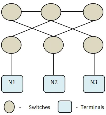
re-Figure 1.1: Interconnect Networks -Bus Topology
tions, which involves intermediate routers or switches are used to establish communication
between nodes. There are many primitive basic interconnection networks which use bus,
crossbar swithces for communication between nodes. But in terms of scalability, as the
number of nodes increases in a bus topology (Figure 1.1) the latency incurred increases
which affects the performance. Same is the case with crossbar switches (Figure 1.2).
This stressed on the need for having routers or switches in between nodes which could
facilitate fast data transfer. Dynamic networks such as ring (Figure 1.3) networks [67]
and multistage (figure 1.4) networks like fat-tree CLOS networks [70] were developed for
the same. Low radix routers [62] were designed, which supported multi-stage networks
and led to the advent of hypercubes - cosmic cube [6] which uses either 2D Mesh or torus
networks.
While designing an interconnection network we need to take into consideration of three
aspects, the topology between the nodes in the network, an algorithm which governs the
routing between them and finally controlling the flow of packets in the network [78]. There
are published references [25] explaining the detailed operation of various interconnection
networks. Today science has advanced to such an extent that the performance expected
Figure 1.2: Interconnect Networks - Crossbar switches
radix routers [80]. As shown in [62] low radix routers have few number of ports which
have fat links whereas high radix routers have more number of ports and thus skinny
links.
Topologies used in an HPC environment include Fat-tree (CLOS [8]), Infiniband [89],
Mesh and 3D-Torus. Custom topologies [96] can also be constructed to improve the
performance by allocating the operations to each network. Let us take a look at these
topologies which are used for building a high performance communication domain in a
supercomputing environment. Infiniband is a multi-purpose interconnection network which
has the capability to connect thousands of nodes or servers together and providing very
high performance. Infiniband provides three levels of network bandwidth 10Gbps, 20Gbps
and 40Gbps [51]. This topology is limited to cluster supercomputers as the infrastructure
software has to be tweaked in order to support it. It is used for I/O operations and was
primarily developed by InfiniBand Architecture (IBA) [92] to avoid issues created due to
Figure 1.3: Interconnect Networks - Ring Network
host machines and other devices. A new topology “Flattened butterfly ” which is used in
high radix routers is explained in detail in [76] [79]. It is a cost efficient approach and
offers lower latency as compared to other network topologies like hypercube and CLOS.
Flattened butterfly topology is created by configuring routers on each row in a butterfly
topology such that it does not affect the interconnections [76].
Figure 1.5: Interconnect Networks - Mesh Networks
Mesh networks [44] (Figure 1.5) are 2-dimensional networks where the nodes are
arranged in a row and column fashion with each node having a point to point link to its
neighbours. When the end nodes in a mesh are connected back to the first node then the
network becomes a torus network. When high radix routers are used all the communication
between nodes occur through the switches. As shown in (figure 1.6) [1] 3D torus networks
offer direct point to point communication between nodes and provide high performance in
terms of scalability and speed. Redundant channels are provided for each node which can
called as Drangonfly [77] which is used in some Cray manufactured supercomputers. This
technique uses high radix routers as virtual routers and further more it reduces the number
of global channels required for the system and results in reducing the cost. Routers are
grouped together using local channels which constitute the virtual router and these groups
are then interconnected using global channels. Thus moving from low radix to high radix
routers increases the network bandwidth and scalability. These topologies are used in
most of the recent supercomputers due to their low latency and high performance.
Figure 1.6: Interconnect Networks - Torus Networks
1.5
Motivation for Dynamic Topology Construction
We have seen that the major problem with loosely coupled systems or clusters is that
they use Ethernet communication between nodes resulting in sometime unacceptable
network latency. It is easy to configure nodes in a cluster based on the requirements,
for compute intensive applications and workflows. In compute intensive applications
data needs to be transferred between nodes at a very high rate. Also fast links are
needed to access the storage space. We can create clusters which provide the users with
high processing power but network connections between nodes should be fast enough
to support the fast processing of data. In such cases, tightly coupled systems such as
using a supercomputing environment is used for various scientific applications and other
HPC applications which require high processing power. As seen in the above section
in a supercomputing environment various interconnect topologies are constructed to
connect the processor units of nodes. We can implement various scientific problems using
such a topological environment. There can also be cases where it might be beneficial to
create a data flow workflow of the problem and have different nodes perform different
operations. We can have the data distributed between nodes. Apart from this there can
also be workflows which needs to implemented over a custom topology where isolated
communication domains like VLAN’s [43] need to be created.
Figure 1.7: Scientific Workflow Topology example [98]
Figure 1.7 shows a scientific workflow which was designed using Kepler [28] in [98].
processing models including simple data flow, distributed data flow, and process networks.
This makes it appealing to map workflows written in Kepler, which is used to implement
scientific workflows, onto a flexible dynamic topology that would coincide with the data
operations the workflow implements. We can see that three are three main streams. In the
first part a single node is dedicated to perform NetCDF processing, second part another
node is assigned to perform HDFS processing and the third stream performs an M3D
OMP process but has multiple nodes involved. The most important functionality that we
can infer from Figure 1.7 is that every single node is assigned a unique function to perform
and are different from each other. There are three different data processes that occur
parallely. Such an implementation can offer better performance in some cases as opposed
to using the fixed underlying architecture. This motivates the need of having a software
defined networking [85] on the supercomputing hardware which provides the flexibility of
configuring networks on the fly than doing them manually based on the requirement. This
is analogous to creating a virtualized layer over the hardware thus providing dynamic
network configuration. It is essential to have such a technique to cater the rising demands
of computation and data analytics. Thus instead of mapping the application and problems
to the fixed network architecture we can construct a data flow model of the problem and
create a topology to execute them.
In this thesis we create an environment using VCL and IBM KittyHawk which provides
the functionality of constructing dynamic network topologies between nodes on IBM
BlueGene/P supercomputer. KittyHawk is a tool that runs on the BlueGene Login node
which provisions BlueGene nodes and creates custom networks to which nodes can be
added. We can consider it like a provisioning agent. Just as we would use Vmware to
create virtual machines and configure a network between them, KittyHawk provides the
provisioning agent into VCL which then provides a complete soft-version. VCL provides a
well defined user interface to the user through which they can request for specific number
of nodes and networks and then construct a topology between them. This information
is passed onto the KittyHawk modules. VCL has a very flexible design through which
resources are controlled. We assign these raw BlueGene nodes as computer resources
in VCL and these computers have KittyHawk as their provisioning engine. A user can
reserve the topology from VCL User Interface and run applications or workflows on them.
Detailed explanation of the system environment, design and implementation is given in
the following chapters.
In chapter 2 we describe the environment used. We first describe about BlueGene/P
supercomputer, the hardware architecture, node specifications, how they are organised
and finally the interconnection networks between them. Later on we describe features
of kittyhawk and how they create a logical communication domain over BlueGene
envi-ronment. We also provide details about VCL architecture, the services it provides etc.
In Chapter 3 we describe the system design. This section is further divided into two
parts. First section explains how KittyHawk is configured and designed for our system
environment and the next section presents a detailed design of VCL. In chapter 4 we
describe the installation and integration of these modules and also go over the system flow
based on an example. Chapter 5 talks about the experiments and results. We conclude
the discussion in chapter 6. Detailed installation manual steps and figures for the results
CHAPTER
2
Environment Used
The main focus of this project is to create an environment on a supercomputer where the
interconnectivity between nodes can be reconfigured based on the data flow model of a
workflow. Supercomputers have fixed architecture at their node interconnect level. We
create a soft-version which will enable a user to create logical custom interconnections
between the nodes. We implement the same on IBM BlueGene/P supercomputer. The
software layer is created by integrating KittyHawk and VCL. Thus we have three main
systems which are integrated together to provide the proposed system. Before we get into
the system design and configuration it is essential to understand the system components.
In this chapter we will go through each of the components briefly and understand how
they are configured. We will first go over the BlueGene/P architecture, the hardware and
the sections ahead we will go through the various components of VCL and KittyHawk
and how they function.
2.1
IBM BlueGene/P Architecture
IBM Bluegene is a project which aims at producing next generation supercomputers which
achieve operating speeds in the Petaflops range. There are three ranges of computers
BlueGene/L, BlueGene/P and BlueGene/Q.
The heart of BlueGene is a Node which contains these two elements a processing unit
which controls all the processing tasks and an interconnect controller which is used to
manage interconnection between nodes. These systems are efficient in terms of power
consumed. We split the BlueGene Hardware into three sections, first Node Model where
we will describe the components of each node and the processing power etc. BlueGene
Architecture is made up of different types of nodes such as front end nodes, compute nodes,
I/O nodes etc and their functionality is described in the section Node organisation. It is
essential to see how these nodes interact with each other using the various Interconnect
Models.
2.1.1
Node Model
The central unit in a BlueGene/P computer is a quad-core chip also called as a Processing
node. It consists of a 850 Mhz Quad Core PowerPC CPU with 2GB of RAM and an
Interconnect Controller. These chips are loaded onto a Compute Card shown in Figure 2.1
with one chip on each card which achieve upto 13.6 GFlops of operating speed. Many such
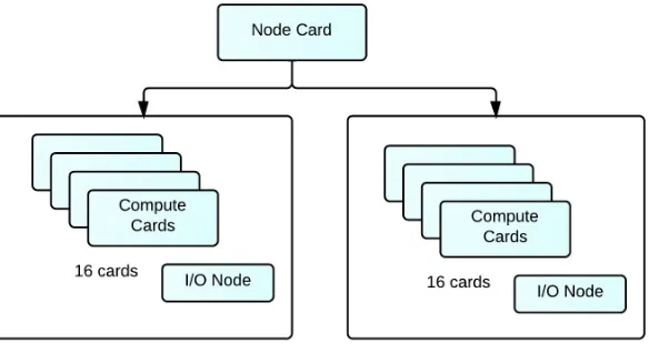
consists of an 850Mhz Quad-Core PowerPC CPU with 2GB of RAM and also has a 10G
Ethernet Controller for communication with external world. With 32 nodes, each node
card has 32 * 2 = 64 GB of memory and an operating speed of 435 GFlops. The next
aggregation level is the rack shown in Figure 2.3 where 32 node cards are stacked together
to form one rack. There are two mid-planes with 16 node cards on each plane. Putting
together each rack contains 1024 nodes ie 4096 cores and a total memory of 2TB and
peak operating speed of 13.6 TFlops. A petaFlop operating system is achieved when 72
such racks are combined together.
Figure 2.1: BlueGene/P Compute Card Components
2.1.2
BlueGene Node Organization
There are four types of nodes in a BlueGene/P Environment as shown in Figure 2.4
(referred from [90]). They are compute nodes, I/O nodes, front-end nodes and service
nodes. As mentioned above these nodes are quad core nodes with 2 or 4GB memory.
Users do not have access to the compute nodes which are used to run various applications.
Figure 2.2: BlueGene/P Node card components
All the I/O operations from these compute nodes are directed to the I/O node as it
has external access through a 10 Gigabit network connection. I/O nodes provide various
functionalities such as starting a process, network connections etc. The ability for the
users to login into the system and compile and submit jobs to the BlueGene nodes is
provided by the front-end nodes. Using this node the user can start, delete and check
the queue status of a job that is submitted. For such a complex system there should be
constant monitoring of nodes for various security aspects. These services are provided by
the service nodes which perform monitoring, synchronization and management services.
Analogous to the compute nodes the users do not have access the service nodes.
2.1.3
Interconnect Models
There are 4 types of interconnection networks namely 3-Dimensional Torus Network,
Collective Network, Global Control Network and 10Gigabit Ethernet network which are
used by the BluGene Nodes to communicate between each other and to the outside world.
Let us take a look each of the networks.
Global Control Network: This network is used to send boot configurations when
the BlueGene/P nodes are booted up. For example when we use KittyHawk it
uses this network to communicate with the nodes and send them with the various
boot-related information. The boot-loader firmware is loaded on these nodes using
this control network.
Torus Network: In this network every node is connected to every other node. It
basically connects all the compute nodes and creates a point to point communication
between them. Every node will have links to its 6 neighbours and in total there will
be 12 links as we need to count both incoming and outgoing links.
Collective Network: This is analogous a hierarchical network which connects all compute and I/O nodes together and can be used to send broadcast and multicast
messaged to the compute nodes.
10GBit Ethernet Network: As mentioned in the section 2.1.2 each I/O node is
2.2
KittyHawk
KittyHawk [48] [37] is a system software that was developed to explore the use of a global
scale shared computer to host various applications. It was build on BlueGene/P and
thus creates a platform which can be used to run various heterogeneous workloads. It
provides a software environment which helps in building various solutions and services on
a supercomputing environment which takes into consideration implementation complexity
for BlueGene/P. The main goal of Kitty-Hawk is to reduce the software that is needed to
provide a service developed on BlueGene/P [47]. It provides an abstraction layer which
utilizes the benefits of the underlying hardware. BlueGene/P nodes can be considered
as computational resources with specific memory, storage, network interfaces with the
ability to load an kernel image through a software like KittyHawk.
2.2.1
KittyHawk Features
Scalable hardware and proper software provisioning are two important aspects required
in a global scale system [48]. Today there are two major computational environments:
tightly coupled systems and loosely coupled clusters. Kitty-Hawk designers argue that
loosely coupled clusters or systems which use shared memory cannot support a wide
range of applications [48]. While designing such a system it is important to make sure
that the applications running on top of such a hybrid architecture are able to utilize the
performance. Loosely coupled clusters do not share memory but use various virtualization
techniques which might affect the performance of the application. Thus hybrid computing
environments should be able to provide the best performance for heterogeneous workloads.
Reliability and sustainability of the system is also very important while developing such
with custom or torus node interconnects between them. KittyHawk helps to create a
logical network between a pool of nodes where nodes do not share memory and can be
easily configured for the required application or workflow. Raw computational nodes are
loaded with a very basic boot-loader followed by a software image which consists of kernel
image and ramdisk image which configures the nodes based on the specified command
line arguments. These images can are either loaded using a Push Model or a Pull Model.
In Pull model the image to be loaded on the nodes will be stored on an external storage
which can be accessed using NFS storage or nbd-server / client where as in a Push model
the kernel image is pushed onto the node via the network.
2.2.2
KittyHawk Abstraction : Communication Domains
Communication Domains help to create a flexible abstraction over the hardware
inter-connects. KittyHawk provides the flexibility to define a communication domain between
the nodes. For example if we define a node to have the ability to communicate with with
two different networks then it will have two network interfaces at the software level with
each interface defined for a corresponding network. This is similar to creating smaller
host-only subnets inside a network. KittyHawk enables the implementation of such custom
communication domains where users can add nodes to specific networks or remove nodes
from a network. As seen in the previous section where we described about the interconnect
model of BlueGene/P, at the hardware level each node is associated with an identifier
which defines it location on a torus like network. Kitty-Hawk provides the ability to
develop a logical layer where users can construct groups of nodes with certain set of access
rights which will define the communication domain. KittyHawk also provides a method
performance for compute-intensive applications. It uses a distributed memory caching
system called “memcached (memory cache daemon)” to utilize RDMA (Remote Direct
Memory Access) features of BlueGene/P hardware [49]. Memcached [68] is a distributed
caching system which provides high performance to various applications such as caching
database query results to reduce the load and contention. KittyHawk uses a modified
memcached system which at the lower layer can invoke calls to the torus network driver
and thus uses the torus network RDMA to transfer data between the nodes.
2.3
Virtual Computing Lab (VCL)
Virtual Computing Laboratory (VCL) is an open source Cloud Computing Platform
developed at North Carolina State university. It was a concept desgined by Vouk and
Averitt et al [94] and aimed at providing on demand services to the university. Today VCL
is the top level Apache Software Foundation project [99] [59] which provides on-demand
cloud services which includes physical, virtualized, storage, networking and software
resources. VCL provides more than 80,000 reservations and 7 million hours for HPC
[32]. It offers wide range of flexible services like Infrastructure (IaaS) [60], Software and
Platform (SaaS and PaaS) [87] [88] as well as High Performance Computing Clusters. It
provides single seat desktop reservations, hypervisor based platforms with the flexibility
of underlying hypervisor such as VMware, KVM, Xen and combination of various services
to individuals. HPC services and Network Virtualization are important features in VCL.
2.3.1
Services Provided by VCL
VCL provides the basic service of Infrastructure. It can be either in the form of bare-metal
hardware. VCL also supports both hardware and software virtulization. It uses IBM
Extreme Cloud Administration Toolkit [73] for provisioning bare-metal loads. For software
virtulizaton it uses hypervisors like Vmware server, KVM etc. Over this infrastructure
it has the capability to provide PaaS, SaaS and AaaS. It provides various Linux and
Windows environments as a platform for various research purposes. For example the
XINU image environment is a custom made linux kernel and is used by students to
modify and develop and create a new platform out of it. VCL has hundreds of images for
various software and application environments. Based on the privilege level a user can
obtain a fixed time reservation or long term reservation for an image. VCL provides a
block allocation service wherein a block of nodes can be allotted for a particular purpose.
Reservations can vary from single-seat reservations , to group reservations (Server Profile
function added in VCL 2.3). Cluster reservations functionality can be used for accessing
HPC services through a login node.
2.3.2
VCL Architecture
As mentioned by Averitt et al in [32] there are seven major parts in the architecture as
shown in Figure 2.5,
End User Interface
Authentication Mechanisms
VCL Manager
VCL Database
Image Repository and Storage
Figure 2.5: VCL Architecture - referred from [32]
End User Interface : This serves as the online portal where users can connect into VCL front end and request for an environment. They have to go through an authentication
phase before getting access into the system. Once logged in the user should be able to
access the reservation system. The duration for which the image can be requested depends
on the privilege level of the user. There are four levels of privileges in VCL going all the
way from a basic user to an administrator.
Authentication Mechanisms : VCL uses LDAP authentication [29] for authenti-cating users. Josh Thompson specifies a set of instructions for adding a new ldap server to
VCL in [104]. This mechanism is added to the Web Code by using various php modules.
in the VCL Database.
VCL Manager : This component manages all the request sent to the scheduler. It also provides the interface to access the User Interface as well as Database through secure
authentication services. VCL Manager nodes processes the requests and assigns it to a
management node based on the availability of a resource by checking the database.
VCL Database : This is one of the most important component in the VCL Architec-ture which contains all the necessary information related to resources. VCL classifies its
resources into four major categories [106] Images, Computers, Management Nodes and
Schedules. These resources are mapped to each other. Information related to each resource
is stored in various tables. Apart from resource information it also contains information
related to user credentials, requests and reservation that are being processed, or will be
processed etc. It also contains various log informations for computers, images etc which
can be used for reservation specific analysis.
Node Manager : This node is responsible for managing resources under it. There might be 50 - 100 physical blades which are assigned to each management node which
is capable of processing requests for both bare-metal loads and virtual machines. Once
the scheduler forwards a reservation request to a management node it is its job to find a
computer which can be used for the same. Every management node keeps querying the
VCL database at regular intervals of time.
Image Repository and Storage : Storage is an integral part for any cloud environ-ment. VCL uses data-stores on NFS mounted storage and have been looking into using
SAN storage for the same. Images created in VCL are saved in these data-stores. Storage
2.3.3
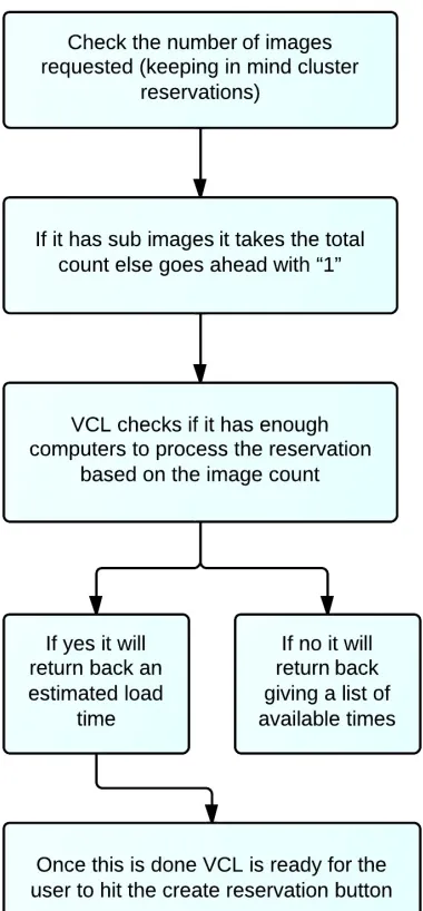
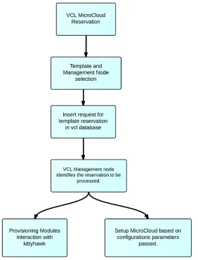
VCL reservation flow
This section describes the basic reservation flow when a user requests for an image in
VCL. There are three phases. The first one is a set of steps that are performed by the
front end modules to check if the requested resources is available or not. This is explained
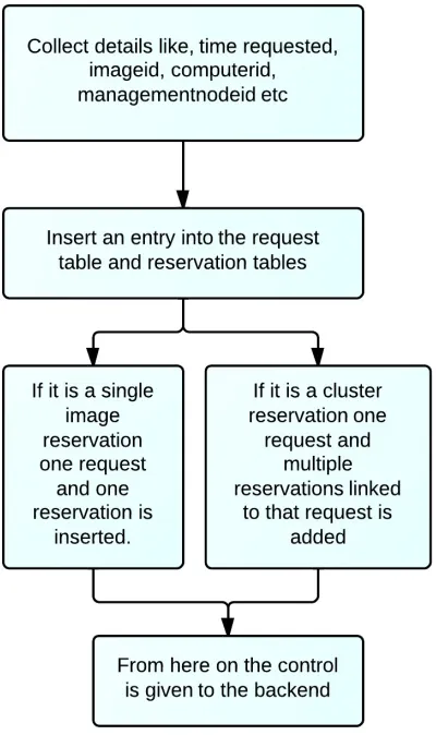
in Figure 2.6. Once VCL makes sure that the request can be processed, in the second
step it again performs various operations as shown in Figure 2.7 and sets up the request
CHAPTER
3
System Design
As we have seen in the previous chapters, supercomputers have fixed node interconnect
architectures and thus do not provide the flexibility to reconfigure them. Thus it becomes
beneficial to have a software layer over these nodes using which we can define the
interconnectivity between them. In our implementation we use VCL and KittyHawk to
develop a software layer over these nodes and thus being able to run scientific workflows
which require a custom network to be configured on the underlying nodes. KittyHawk is
used as a provisioning agent which is driven by VCL to collect nodes, load an image on
them, connect the nodes together in the specified way. For example when we use Vmware
hypervisor to load virutal machines it would follow steps like creating a container based
on the configuration parameters passed to it, create network interfaces as required and
environment by running a Job. VCL passes the necessary configuration parameters like
the total number of nodes, networks etc to KittyHawk and based on this information a
cluster is generated. There are many steps taken by both KittyHawk and VCL during
this operation.
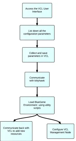
As seen in Figure 3.1 and Figure 3.2 we design the system in two phases. As listed in
Phase I when we consider a Micro-cloud we need certain configuration parameters like the
total number of nodes required, the interconnection between for example topologies like
mesh, star, totally connected or even custom networks, the image that needs to be loaded
on these nodes etc. Once this configuration is saved, KittyHawk scripts will be triggered
to create the environment request. Based on the number of nodes requested KittyHawk
decides the number of Jobs to be executed. KittyHawk utility scripts in turn communicate
back with VCL and updates on resource details. It will kickstart a management node for
each of the Micro-cloud. All these details are recorded in the database.
Phase II describe post management node reservation process. Once phase I is completed,
dedicated set of management node groups, computer groups are added in VCL and all
the BlueGene nodes are added into these groups. The next part will be to go through the
vcl template reservation phase. Users should have the flexibility of choosing the template
they wish to reserve from the pool of templates. Once the reservation button is hit, the
management node running on the BlueGene node is notified that a reservation needs
to be processed. When the nodes are reserved as a cluster reservation, one of the nodes
will be assigned as parent node and the rest as children. New provisioning and operating
system modules which are specific for BlueGene nodes interact with KittyHawk scripts
and process the reservation. Once all the requested nodes are reserved vcl web interface
of how both KittyHawk and VCL modules have been designed and integrated with the
already existing system.
3.1
KittyHawk Design
KittyHawk provides a software platform over BlueGene/P over which we can run
het-erogeneous workloads. Using it we can load numerous instances of Linux on BlueGene
nodes. A debian linux image is loaded on all the nodes. These nodes can be considered as
resources with a few cores, memory and network interface for communicating with the
control server and other nodes. Along with the kernel image a small bootstrapped ramdisk
is loaded onto these nodes. A ramdisk is an image of the root file system. This has the
bare minimum applications installed on it for the specific purpose. All these nodes are raw
nodes have nothing installed on them. KittyHawk loads a firmware on these nodes and a
bootloader uBoot is brought up on these nodes and then finally an operating system to
get the nodes operational. All these functionalities are performed by various KittyHawk
utility scripts. Lets have a look at them in detail.
3.1.1
Workflow on BlueGene/P
In this section first we will walk through as to how KittyHawk sets up a BlueGene node
as fully functional resource. It performs the following steps for the same.
Job Submission on BlueGene Environment
Loading the KittyHawk control server
Loading kernel image on the nodes
Loading ramdisk on the nodes
Loading Lenny / L4 kernel image on the nodes (Lenny is a stripped down debian
image with basic essential linux packages for a powerpc architecture)
Job Submission on BlueGene Environment : In BlueGene Environment an ap-plication can be executed on the nodes through a Job submission. Cobalt-mprium job
submission is used for the same and the command to be issued is “qsub (number of nodes)
(time in minutes) (project name) (other options) (script)”. As we can see we can mention
various details while requesting a pool of nodes. Script is the file that needs to be executed
on the nodes. Other options include configuration options like the network connectivity
like torus networks, mesh etc, execution mode, queue to be used. All these details are
explained in [82]. KittyHawk uses script “khqsub” for Job submission. This is a script
which is written as a wrapper around qsub. When executed we just need to mention the
total number of nodes and time in minutes. For eg. if we need a pool of 64 nodes for 60
minutes the command would be
Command: khqsub 60 64
The script then builds the cobalt-mprium submission command based on the command
line arguments and environment variables and the command issued is
Command: qsub -n 64 -t 60 -e stderr -o stdout –debuglog debuglog -q default -A
VCL-ON-BG P –kernel kh /home/georgy/null.elf
into the shell before running this command. This job is executed on the login node and it
returns back with a compute node partition exclusively for the user.
Loading the KittyHawk control server : At the end of the job, a KittyHawk control server node is configured to control all the further requests. As mentioned above a
compute node partition of 64 nodes is allocated to a particular user and is not shared with
other users who are also running a BlueGene Job. khqsub returns back the IP address of
the KittyHawk control server which needs to be exported at the shell.
Command: export khctlserver=(IP)
The environment variable khctlserver is now set and thus can be used by other utility
scripts for further processes. Interaction between the scripts on the login node and the
khclserver uses key based authentication. During the Job submission itself, the keys are
loaded into khctlserver for password-less ssh access.
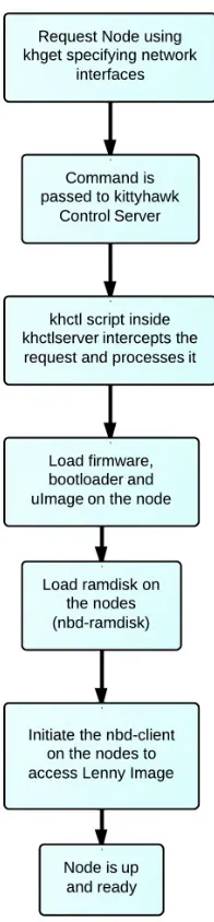
Configuring nodes with custom interfaces : Once we have the pool of nodes we can provide a custom configuration for each of the nodes and load them with a linux
kernel on them. The first step is to get nodes and pass network interfaces parameters. The
command used for this “khget (options) (number of nodes)”. The options are as follows
-x : to add the node to the external network
-i : to add the node to the internal network
user : user to get the nodes for
-p : Number of new private networks to be created
Thus if we want to request for a single node the command to be issued is node=”$(khget
-x -i $USER 1)”. node is an shell environment variable assigned and $USER will
con-figure the node for the currently logged in user. The options provided are -x and -i,
this will add two network interfaces for the node one for the external network and the
second for external network. Option -p is used when we want to add private custom
networks. Each time a private network is created there is a “netid” associated with each
of the network. Thus later on if we wish to add a node to the existing private network
we can just specify this netid using the -n option. In our implementation these options
are extensively used as we need to created custom private networks and add nodes to them.
Loading kernel image: Once the node is requested, KittyHawk loads a BlueGene/P specific firmware on each node using the Global secure control network. Once the firmware
is loaded the boot loader is brought up on the nodes. The next step is to load a kernel
image on these nodes ”uImage”. This is again loaded using the “khdo” utility script which
has a function called as loadkernel. These images are used with uBoot Boot-loaders and
they contain information about the linux kernel, root file system, firmware etc. Once this
is done, the node is up and running for use. We can transfer the public key into the node
and then perform ssh based on public-private key based authentication.
Loading ramdisk on the nodes : As mentioned earlier ramdisk is an image of the root file system. We can configure any application as a ramdisk file and then load it on
the node. For example we can have a ramdisk with sshd configured on it and thus after
loading it on the node we will be able to ssh into it. In the basic setup KittyHawk loads
remotely. nbd server is intitated on the login surveyor node and an nbd-client ramdisk
is loaded on the Bluegene Nodes which connects to the server. It gives the notion of a
disk loaded locally on the node. The debian lenny image is loaded on the disk which is
then mounted and accessed by the nodes using nbd-client. This is a persistent disk and
thus any changes made to the image will be changed. Loading the ramdisk is managed by
“khdo” utility script which has a function called loadramdisk.
khdev utility script : This entire procedure can be done through a single utility script called as “khdev”. It does all the functions that are mentioned above like requesting
node, loading uImage, loading ramdisk and finally setup nbd-server and client and load
lenny image to create a remote disk for the nodes. keys are also loaded in the nodes via the
script so that further ssh communication can happen via key based authentication. The
command that is issued is : khdev -K ”$(cat /.ssh/id rsa.pub)” (path-to-lenny image).
-K option specifies the key to be loaded on the node and the second parameter is the
path of the lenny image. But there is a limitation in this script. It configures a node with
only two interfaces, one for public interface and other for internal network. We wont be
able to configure custom private network interfaces. Figure 3.3 provides a diagrammatic
representation of the entire process flow.
3.1.2
Configuring Modules
In the previous section we have seen the KittyHawk process flow and the various steps it
undertakes to configure a node completely. All the individual steps are put together into
requirement. The default options which khdev provide are as follows:
-d : Perform Debug during script execution
-k : kernel image to be loaded overriding default one.
<root disk image>: Location of the Lenny image
-r : ramdisk to be loaded overriding default one.
-K : Public ssh key to be loaded on the node to provide root access
By default this assumes that the node needs to be added on the public (-x) and private (-i)
network. But in a cluster network this is not true we need more custom private networks
and any node can be a part of any network.
Figure 3.4: Cluster Example on BlueGene/P
As we can see in Figure 3.4 there are 7 nodes are each of them are connected to different
as private networks in KittyHawk. Also extending further VCL uses two networks for
managing resources, one public for external access to users and the second an internal
private network for back-door management. Thus considering the integration with VCL
we need to design the networks based on it. The public network on BlueGene (-x option)
is used for external access and the internal private (10.x.x.x) network (-i option) is used
for back-door management network. In Figure 3.4 there are 6 custom networks, first we
need to create these networks using -p option and a specific netid will be assigned to each
network and later we can assign the netid’s to nodes. We add these option features and
create new khdev scritps.
While creating a cluster one node is assigned as the management node which runs VCL
and configures the remaining cluster. Cluster template configuration is provided by the
user form VCL Web Interface. This specifies the total number of private networks. These
networks are configured when the management node is created. We create a new script
called as ”khdev mn”, with new options added for “-p” which can be specified as command
line argument while initiating the script. Command : khdev -p (no of custom networks)
-K ”$(cat /.ssh/id rsa.pub)” (path-to-lenny image). Thus when the management node is
requested the function gethost() while requests for a node send the following command to
the khct control server. Command:node=”$(khget -x -i -p (number )$USER 1)”. Once
the management node is up and running it will have all the networks configured on it.
During further template reservation which is processed by the management node, the
new nodes needs to be attached to the custom private networks by using the netid’s. In
order to provide this we add another options field “-n” in the new khdev script. For eg.
khdev -n 2,3,4 -K ”$(cat /.ssh/id rsa.pub)”. This will request for a node which needs to
VCL provisioning modules.
3.2
VCL Desgin - Front End and Back End
As seen in the VCL Architecture in the previous chapter there are three main components.
MySQL database which contains all the information about various physical and virtual
resource, images, user groups and role based privilege access lists. We need to add new
tables into database to support the new functionality. Details will be selected and inserted
from and into the database by both the front-end and back-end VCL modules. VCL
front-end provides User Interface functionality for users. Apart from the regular tabs
in VCL dashboard we will add a couple of tabs and access to these can be restricted
using privilege tree functionality in VCL. Front end modules are php based and dynamic
update of contents on a page are done using JavaScript and AJAX. We will stick to the
modularized architecture and add new modules based on the existing code structure.
VCL uses continuations [105] to control the sequence of pages. This provides additional
security where users will not be able to access pages where they are not authorized to
or perform man in the middle attacks. We will see that BlueGene Nodes are added into
VCL as specific computers. In VCL we have a type field associated with each computer.
Type ”virtual machine” is assigned to virtual resources, ”blade” is assigned to physical
resources. Each type is associated with a specific provisioning and OS modules for
back-end provisioning. In our system we create a new computer type called ”bgp” and create
new provisioning modules which are linked to BlueGene Nodes. Finally we need to add
modules which will manage the interaction between VCL and KittyHawk utility scripts
3.2.1
User Interface
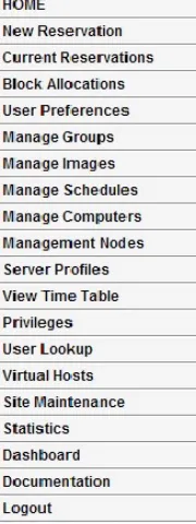
VCL provides a very structured User Interface for managing the resources. Resources are
grouped into computers, images, management nodes, schedules etc. The various resource
attributes are mentioned in [106]. As we can see in Figure 3.5 there are tabs that are
provided for managing each of these resources. Computers are managed through “Managed
Resources”, images are managed through “Manage Images” etc.
Figure 3.5: VCL User Interface Tabs
Each tab has its own php file which displays and manages the different functionalities.
For dynamic update JavaScript functionality is used. For our system we will create two
additional tabs. First one called as ”HPC-BGP” and the second one ”HPC-Template”.
file which contains all the functions and a JavaScript to take care of dynamic updates.
Already existing modularized architecture of VCL code is maintained while adding these
two tabs. Once these tabs are created we need need to decide the functions that they need
to provide. For our system we know that before we request for a pool of nodes we need to
create a topology or a template which will have all the custom configuration parameters.
Once this is done a pool of nodes can be requested and the management node can be
configured. Finally we should be able to reserve the template that we created initially
which is send as a cluster reservation to the management node. Hence we need to provide
four functions in total which are as follows:
Create Template
Management Node and Pool Reservation
Template Reservation
Delete Base Node and Pool
The first functionality to be added is ”Template Creation”. While defining the template
the user needs to provide two details one the total number of nodes required and second the
total number of custom networks. Based on the information provided a two dimensional
matrix of nodes v/s networks is provided to the user. The user can now map between the
nodes and the corresponding network need for each of them. Table 3.1 shows the mapping
between nodes and networks. As mentioned in the section above we have two mandatory
network interfaces for each node external network and internal network.
This mapping information is saved in the database table. The second functionality
to be provided is triggering a BlueGene Job and reserving a Management Node. It is
![Figure 2.5: VCL Architecture - referred from [32]](https://thumb-us.123doks.com/thumbv2/123dok_us/1573983.1193615/39.612.133.495.121.364/figure-vcl-architecture-referred-from.webp)