Liquefaction Susceptibility of Kolkata Soil and
Best Suitable Method to Avoid Liquefaction
during Earthquake in Kolkata
Pinak Ray 1, Esha Das 2
Assistant Professor, Department of Civil Engineering, Techno India University, Kolkata, West Bengal, India1
U.G. 4th Year Student, Department of Civil Engineering, Techno India University, Kolkata, West Bengal, India2
ABSTRACT: Soil liquefaction is the most hazardous phenomenon for the buildings. Some conceptual and basic factors related to soil liquefaction has been addressed here. Liquefaction mechanism, different kinds of factors affecting soil liquefaction, and evaluation of liquefaction susceptibility of soil has been discussed. An extensive study of Kolkata sub soil characteristics have been carried out and the Kolkata and Kolkata surrounding areas which can be highly affected by soil liquefaction have been evaluated. The most suitable ground improvement technique to counteract liquefaction during an earthquake of certain magnitude has been proposed.
KEYWORDS: Soil liquefaction, Kolkata soil character, Anti-liquefaction Measures, pile driving method
I. INTRODUCTION
Soil plays a very important role for a building to stand still, it’s quite like human’s feet and the structure of the building is like human’s skeleton. But in nature some disbalance occurs due to the tectonic plate movement, for which disturbance in soil layers can be observed. One of the major phenomenons of disturbance in soil layer due to earthquake is liquefaction. Soil liquefaction occurs due to large earthquakes and it is also termed as ground failure (for flow liquefaction) and sometime it is termed as lateral spreading (cyclic mobility) (Seed, 1979) [8]. Generally soil liquefaction occurs due to less strength of soil. In saturated cohesionless soil due to build-up of pore water pressure due to application of sudden earthquake load, the strength of soil gets decreased and soil liquefaction is occurred (Seed and Lee, 1966) [10]. Several case histories, field and laboratory studies revealed that silty sands (also present in Kolkata sub soil strata) are also prone to liquefaction (Seed et al., 1983; Yamamuro and Lade, 1998) [9, 15]. So on the basis of seismological and geotechnical characteristics; it is necessary to assess liquefaction susceptibility at Kolkata city and also the most suitable ground improvement technique has been proposed to mitigate soil liquefaction.
II. PREVIOUS CASE HISTORIES
There are large numbers of case history where liquefaction has been triggered.
1. Niighata Earthquake (1964): The Niighata earthquake occurred on 1964, June 16 in Japan. Its magnitude was 7.5 and caused severe damage to many structure in Niighata. And it caused severe damage to many structures in Niighata. It destroyed around 2000 houses, and caused damages to many houses.
2. San Fernando earthquake (1971): This earthquake occurred in early morning of February 9 in foothills of the San Gabriel Mountains, in southern California with a magnitude of 6.5 or 6.7.
3. Ninhonkai-Chubu (1983): In 26 May 1983, at noon a major earthquake occurred in Ninhonkai-Chubu (Japan Sea) with a magnitude of 7.9. It damaged around 5100 houses.
4. Borah Peak, Idaho, earthquake (1983): In 28 October, 1983 the largest earthquake occurred in Idaho with magnitude 6.9.
6. Loma Prieta Earthquake, Watsonville (1989): In 1989 on October 18 at 5 p.m. an earthquake occurred in San Francisco with a magnitude of6.9.
III. MECHANISM OF SOIL LIQUEFACTION
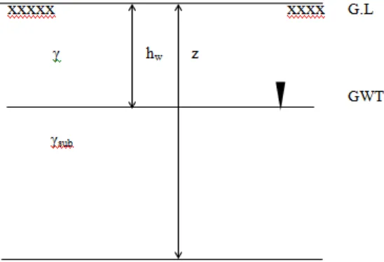
Fig 1 represents a section of ground having sand layer of depth z from ground level (GL) where ground water table (GWT) lies at a depth hw from ground level where unit weight of sand is γ and γsub is saturated unit weight of sand.
The shear strength of sand is primarily due to internal friction (cohesion, c = 0). In saturated state it may be expressed as: (Fig 1)
Fig 1: Section of ground showing the position of ground water table σ = σ'n tan ϕ
Where,
σ= Shear strength.
σ'n = Effective normal pressure on any plane.
ϕ = Angle of internal friction
Due to ground vibrations, saturated sand tends to compact in volume. As the earthquake load acts suddenly for very short period of time the pore water pressure cannot be dissipated as a result it becomes in undrained condition. The shear strength of sand can be expressed as:
σdyn = (σ'n- udyn) tan ϕdyn
Where,
σdyn = Shear strength of soil under vibrations.
udyn = Excess pore water pressure due to ground vibrations.
ϕdyn = Angle of internal friction under dynamic condition.
It is seen that with development of additional positive pore water pressure, the strength of sand is reduced. In sands,
ϕdyn is almost equal to ϕ, i.e. angle of internal friction in static condition.
For complete loss of strength, i.e. σdyn is zero.
Thus, σ'n- udyn = 0
Or, σ'n = udyn
Or, udyn / σ'n = 1
Expressing udyn in terms of rise in pore water head, hwand submerged unit weight, γsub as (G – 1/1+e).γw:
γ .
– / . ɤ . = 1
Where,
G = Specific gravity of soil solids. e= void ratio
icr = critical hydraulic gradient.
It is seen that, due to increase in pore water pressure the effective stress reduces, resulting in loss of strength. Intergranular stress gets transferred from soil grains to pore water. When this transfer is complete, there is complete loss of strength, resulting in what is known as complete liquefaction. In case of complete liquefaction, the effective stress is lost and the sand – water mixture behaves like a viscous material and process of consolidation start, followed by surface settlement, resulting in closer packing of sand grains. Thus the structures resting on such the material start sinking. The rate of sinking of structures depends upon the time for which the sand remains in liquefied state.
Liquefaction may develop at any zone of a deposit, where the necessary combination in situ density, surcharge conditions and vibration characteristics occur.
Thus, an important feature of the phenomenon of liquefaction is the fact that, its onset in one zone of deposit may lead to liquefaction of other zones, which would have remained stable otherwise.
IV. TYPE OF FAILURES OF SOIL DURING LIQUEFACTION
There are three basic types of ground failure that commonly result from liquefaction. They are as follows: 1. Flow Failures:
Very large scale landslides can be referred as flow failures occur in sloping areas, inclined at 5 percent or greater. The most damaging type of ground failure caused by liquefaction is flow failure.
Example: Liquefaction failure of Sheffield Dam (Santa Barbara Earthquake, 1925) 2. Lateral Spreading:
The most common type of ground failure occurred by liquefaction is lateral spreading. As a result of liquefaction in underline layers, there is a lateral displacement of large box of intact, surficial soil. Lateral spreading generally develop on a 3 degrees flat gentle slopes and move toward a free phase.
Example: Lateral spreading of very flat ground toward the Motagua River (Guatemala Earthquake, 1976) 3. Ground Oscillation:
By decoupling of overlying soil blocks, liquefaction at the depth may create separation at the surface. When the ground is too flat to permit lateral movement, it allows the blocks to jostle back and forth on the liquefied layer.
V. FACTORS AFFECTING LIQUEFACTION SUSCEPTIBILITY OF SOIL
Composition of the soil mass:
Coarse grained soils mainly sand are most prone to liquefaction. Liquefaction of nonplastic silts has been observed (Ishihara, 1993) [6] indicating that plasticity of soil rather than grain size alone influenced the liquefaction susceptibility in case of fine- grained soils. Soil satisfying each of the following four Chinese criteria (Wang. 1979) [13] may be considered susceptible to liquefaction:
Fraction of soil particles finer than 0.005mm ≤ 15 %
Liquid limit, LL ≤ 35 %
Natural water content ≥ 0.9 Liquid limit Liquidity index ≤ 0.75
Grain-Size Distribution and Soil Types:
Friction between particles mobilizes the resistance to deformation of the type of soil most susceptible to liquefaction. The frictional resistance of cohesion less soil decreases as the grain size of soil becomes smaller if other factors such as grain shape, uniformity coefficient and relative density are equal. Uniformly graded soil is more susceptible to liquefaction than well graded soil.
Relative Density:
The magnitude and number of cycles of stresses or strains induced in it by earthquake shaking, controls the vulnerability of any cohesion less soil to liquefaction. Duration of ground shaking, predominant frequency and intensity are related to it.
Vertical Effective Stress and Over consolidation ratio:
Since an increase in the effective vertical stress increases the bearing capacity and shear strength of soil thereby increases the shear stress required to cause liquefaction thus decreases the potential for liquefaction. Saturated sands located deeper than 50 to 60 ft. are not likely to liquefy.
Age and Origin of the Soils:
Generally soil grains in the state of loose packing are present in natural deposition and fluvial origin. Due to cementation and ageing these deposits are young, weak and free from added strength.
Seismic Strain History:
Prior seismic strain history can significantly affect the resistance of soils to liquefaction; Series of previous shaking producing low levels of excess pore pressure, can significantly increase soil resistance to pore pressure build-up during subsequent cyclic loading is a result of low levels of prior seismic strain history. Large pore pressure generation and conditions of full liquefaction can develop weak zone in the soil due to uneven densification and redistribution of water content (Whitman, 1985) [14].
Degree of Saturation:
In dry soils liquefaction does not occur. Partial saturated sands are little susceptible to liquefaction. The sand samples with low degree of saturation can become liquefied only under severe and long duration of earthquake shaking which shows liquefaction resistance for soil increases with decreasing degree of saturation (Sherif et al., 1977) [11].
Thickness of Sand Layer:
The liquefied soil layer must be thick enough so that the resulting uplift pressure and amount of water expelled from the liquefied layer can result in ground rupture such as sand boiling and fissuring, in order to induce extensive damage at level ground surface from liquefaction.
Previous Strain History:
Some strain history revel are subjected by previously similar deposits which are studied on liquefaction characteristics of freshly deposited sand, the strain history revel are though the prior strain history caused no significant change in the density of the sand, it increased the stress that causes liquefaction by a factor of 1.5.
VI. DETERMINATION OF LIQUEFACTION SUSCEPTIBILITY OF SOIL
A detailed understanding of site conditions, the soil stratification, dynamic soil properties, their variability, and the areal extension of potential critical layers should be developed. Simplified field tests like CPT, shear wave velocity test, SPT etc. are widely used in practice to characterize the soil stratum to obtain cyclic resistance ratio (CRR). Corrections of the data should be applied as necessary, e.g. the normalized SPT blow count [(N1)60] or the normalized CPT value.
Designed earthquake should be calculated by multiplying CRR value with earthquake magnitude scaling factor (MSF). Calculation of the stress for the liquefaction of critical zones is necessary, depending on the characteristics of the critical zone(s) (e.g., normalized standardized blow count, fine content, overburden stresses, level of saturation). Mainly to cyclic stress ratio (CSR) or τav / σv0' where τav means developed shear stress during earthquake and τh, shear
stress required to cause liquefaction.
For each liquefaction susceptible critical layer, computation of the factor of safety against liquefaction is to be done.
VII. CHARACTERISTICS OF KOLKATA SUBSOIL
1. Subsoil condition in Kolkata soil:
It has been observed that several locations of Kolkata and its surroundings can be affected heavily due to liquefaction as those regions have river channel deposits by Ganga. The Kolkata city is situated on the left bank of the river Hooghly (Ganga). Kolkata also comes under the seismic zone IV according to IS 1893 (Part 1) 2002. By the Ganga (Hooghly) river system the top layers of the sediment are deposited and are of recent deposit.
There are generally three types of soil layers in Kolkata –
II. River channel deposit: Fine sand is present in the top layer of this soil.
III. Reclaimed land: Fine sands exist in top layer and after few meters silty soil exists. 2. Discussion of contour map:
The equipotential lined contour maps have been obtained for several depths mainly at 2.5, 5, 7.5 and 10 metre with liquefaction potential values using artificial Neutral Network model (Chakraborty et al., 2004) [2]. From the result it is clear that, at 2.5 metre depth, in the adjacent areas of Hooghly River, some areas like Kasba (southern Kolkata), some portion of northern Kolkata like salt lake has liquefaction possibility for acceleration levels 0.1g. Due to soil liquefaction at this depth, extensive damage can be caused by greater earthquake.
At 5 metre depth, higher liquefaction susceptibility for peak ground acceleration level (amax = 0.15 g) in
Rabindra-Sadan area has been found. Some areas of northern Kolkata have a liquefaction probability for acceleration level equal to or greater than 0.15 g primarily, like Dumdum cantonment because of presence of sand layer at 5 metre depth in those regions of Kolkata city. Liquefiable area gets increased due to increase in acceleration levels.
At a depth of 7.5 metre higher liquefaction susceptibility for 0.15 g has been observed in some locations of south Kolkata like Race course and some locations of northern Kolkata like Dumdum, Belgachia.
At a depth of 10 metre liquefaction potential value is more than 1 for acceleration more than 0.15 g, in some areas in south Kolkata like Tolleygaunge, Behala, Kalighat and some areas of northern Kolkata like Belgachia, Dumdum cantonment.
Based on the study of liquefaction potential map for Kolkata it can be stated:
The areas in south Kolkata like Tolleygaunge, Kasba where river channel deposition has occurred are found to be the most susceptible area to liquefaction.
Being a reclaimed area the Salt lake area consists of a top layer of very loose fine sand and after that soft to medium stiff loose sandy silt and clayey silt layer exists which is mixed with decayed vegetations which is also susceptible to liquefaction.
Very less liquefaction susceptibility has been found in central Kolkata areas like Beliaghata, Sealdah. 3. The location on Kolkata which can be affected by liquefaction:
3.1. In Kolkata, depth of water level may be observed in the pre-monsoon and post monsoon. It has been observed that the depth of water level varies generally from 6m to 18m below ground level. In south central Kolkata the depth of water level below ground level lies at 16m. This is indicative of rapid urbanisation in that area and as well as strong over draught. The depth is 12m, at Behala in the far south. The water level is 10m at Thakurpukur and Garia in the south. This is an indication of flowing of groundwater from South and south-west Kolkata to south-central Kolkata. 3.2. The depth of water level varies from 6m to 14m below ground level in the pre and post-monsoon. The depth below ground level is 12m in and around Behala, Jadavpur, Ballygunge, Park Circus, Beleghata and Babughat. The depth of ground water table is 10m below the ground level at Thakurpukur, Bansdroni and at Garia; Kalikapur the depth GWT is below 6m. As a result, a significant difference is noticed in these areas between the pre-monsoon and the post-monsoon. 3.3. Successive layers of clay, silty clay and clayey silt, are present in the top 30m.of the subsurface soil strata in Kolkata and the layers can be subdivided into two parts: Much stiffer materials of clay lies below 15m depth whereas softer components lies on the upper clay horizon (top 15 m.) generally consists of. This stratification is found to exist over most of the study area and is generally known as the Normal Kolkata deposit.
VIII. ANTI-LIQUEFACTION MEASURES
To find out various possible measures to prevent liquefaction a comprehensive study is required. It depends on several numbers of factors; however, few can be controlled in the field. To some extent liquefaction resistance can be improved by:
1. Compaction of Loose Sands:
Loose saturated sands are more prone to liquefaction than dense saturated sand. Therefore, by compacting the sand deposit before any structure is constructed, the liquefaction potential can be reduced. Various methods for compaction of loose sands can be suggested as:
By excavating some depth it may be accomplished, then carefully backfilling in controlled lift thickness and compacting the soil. Lifts are commonly 150mm – 200mm, when rubber tyres are used. However this method cannot be used for compacting deep sand deposit,
1.2. Compaction with vibratory plates and vibratory rollers:
By using smooth wheel rollers commonly with a vibratory device inside, the compaction of cohesion less soil can be achieved. With this equipment, lift depths up to about 1.5m – 2 m can be compacted. Also vibratory assembly can be used with plates mounted; however, small thickness of soil can be compacted by these methods and they cannot be used for large deposits.
1.3. Driving of piles:
When piles are driven in loose deposits, they compact the sand within an area covered by 8 times around it in the sight having loose sand deposit. The overall stiffness of the soil stratum increases substantially since pile remains in the sand. 1.4. Vibrofloatation:
To densify cohesion less deposit of sands and gravel with having not more than 20 percent silt or 10 percent clay, this method is commonly used. Its upper half is stationary part and the lower half is vibrator at the top and bottom the device has water jets. With bottom jet on which induces the quick sand condition, Vibrofloat in lower under its own weight when it reaches the desired depth, the flow of water is diverted to upper jet and Vibrofloat is pull out slowly. Top jet aids the compaction process. A crater is formed when the Vibrofloat is pulled. To the crater formed sand or gravel is added.
1.5. Blasting:
The explosion of buried charges induces liquefaction of the soil mass followed by escape of excess pore water pressure which acts as lubricant to facilitate re-arrangement and thus leading the sand to a more compacted state.
2 Grouting and Chemical Stabilization:
The technique of inserting some kind of stabilizing agent into the soil mass under pressure is known as grouting. Into the solid voids in limit space around the injection tube the pressure processes the agent. To from a stable mass, the agent reacts with the soil or itself. A mixture of cement and water, with or without sand, is the most common grout. 3 Sand Drain:
For radial consolidation which increases rate of drainage in the rate of drainage in the embankment by driving a casing into the embankment and making vertical bore holes, the process of sand drain is needed. With suitable grade of sand, these holes are backfilled.
4 Stone Column:
Vibro replacement is a ground improvement, By means of a crane suspended down hole vibrator, to reinforce all soils and densify granular soils vibro replacement that constructs dense aggregate columns (stone column).
IX. BEST GROUND IMPROVEMENT METHOD SUITABLE FOR KOLKATA SOIL AGAINST
LIQUEFACTION
Pile driving method can be considered as one of the most preferable ground improvement technique. Nowadays Kolkata is developing too fast. A huge number of high rise buildings which require large length of piles, are being constructed in and around Kolkata. There are many places in Kolkata Pile driving is believed to result in an increase in the horizontal soil stress and consequently a change of the at rest pressure coefficient. Soil reaction depends on the pile movement and on the other hand, the pile movement depends on the soil response.
Densification of loose sand by compaction of piles has been done. Loose sand strata often need densification by artificial means to improve their relative density since they are liable to liquefaction during earthquake. The process essentially involves driving a casing that has an expandable shoe into the soil – as in the case of cast – in- situ driven piles – by repeated blows of a hammer.
Pile driving methods: This method can be applied to both displacement piles and non-displacement piles. Displacement piles:
Pile driving by drop hammers:
Pile driving by vibrating:
Usually electrical power or hydraulic power is used for vibratory hammers and it consists of eccentric masses rotating in opposite direction with a housing being attached on the pile head. The amplitude of the vibration is used so that it will be sufficient enough to break down the skin friction of the pile. This method is best suitable for sandy and gravelly soil.
Non-displacement piles: Under reaming:
By providing an enlarged base auger bored piles are sometimes used to increase the bearing capacity of suitable strata, this is the special feature of this type of piles. To implement this technique, the soil should have the capability to stand at unsupported condition. Stiff and to hard clays, (e.g. the London clay) are ideal.
Advantages of using of pile driving method: Residual Benefits:
In many soils, pile driving is relatively using. The substantial load is carried by end bearing piles, since for displacement piles the soil at the toe is in a compacted condition. Driven piles compact the soil and displace it. The removal of soil and considerable subsidence can be required by other deep foundation options, which can undermine the support of adjacent and caused excessive deformations, and this two can result in structural problems.
Cost Effective:
Usually the most effective deep foundation solutions are driven piles. There are no added expenses for sight clean-up or hidden extra costs. For high structural strength the wide variety of materials and shapes of driven piles are available which can be easily constructed. As a result these piles can be driven by modern hammers and increase working loads. Reliable and Available:
All over the country, pile driving contractors can be found the installation methods and equipment is time-tested as well as well proven. Advances in methods, materials, equipment and testing continually combined to improve the efficiency of driven piles.
Huge superior structural strength is present in driven piles. During static testing or static loading, driving piles almost never felt. For making driven piles ideal to resist wind, berthing and seismic loading condition, they consist of high lateral and bending resistance along their entire length. Due to their full-length strength, driven piles can carry a certain permissible amount of eccentricity coming from superstructure loads. To increase lateral load carrying capacity, piles can be driven either vertically or inclined at various angles. In special cases, horizontally piles can also be driven. Environmentally Friendly:
Usually no spoils for removal are being produced by driving pile installations and therefore potentially hazardous or contaminated materials cannot be produced.
X. CONCLUSION
Soil liquefaction is a ground failure which occurs due to large earthquakes. There are several kinds of factors affecting soil liquefaction; many methods are there for anti- liquefaction measures. After analyzing it has been suggested them it has been suggested that ‘driving of piles’ is best method suitable for anti-liquefaction measures applicable to Kolkata city. Since, pile driving believed to result in an increased in the horizontal soil stress and consequently a change of rest pressure coefficient. Though driven piles are most cost effective, environmentally friendly, easily available that’s why it is best for Kolkata soil. By driving the piles into the soil strata not only it increases its bearing capacity but also densify the soil by vibrating and compacting while driving onto the soil. As a result void ratio within the soil reduces substantially there will be no chance of sudden rise of excess pore water pressure. But in case of structures which will require shallow foundation in that case dynamic compaction (for cohesionless soil) and grouting technique (for cohesive soil) would be the most suitable method applicable to Kolkata soil.
ACKNOWLEDGEMENT
The authors would like to thank Department of Civil Engineering of Techno India University, a private university in
REFERENCES
[1] Andrews D.C.A. and Martin G.R., “Criteria for Liquefaction of Silty Soils”, Proc. 12th WCEE, Auckland, New Zealand, 2000.
[2] Chkrobortty P., Pandey A.D., Mukerjee S. and Bharghava A., “Liquefaction Assessment for Microzonation of Kolkata City”, 13th World Conference on Earthquake Engineering Vancouver, B.C., Canada, Paper No. 82, August 1-6, 2004.
[3] Chang, N. Y., “Influence of fines content and plasticity on earthquake- induced soil liquefaction”, Rep., Contract No. DOCW3988-C-0078,U.S. Army Engineer Waterways Experiment Station, Vicksburg, Miss, 1990.
[4] Holzer, T. L., Bennett, M. J., Ponti, D. J., and Tinsley, III, J. T., “Liquefaction and soil failure during 1994 Northridge earthquake”, J. Geotech. Geoenviron. Eng.,125(6), 438-445, 1999.
[5] IS: 1498-1970, Classification and Identification of Soil for General Engineering Purposes, BIS, New Delhi, India. [6] Ishihara, K., “Liquefaction and flow failure during earthquakes”, Geotechnique, 43(3), pp. 351-451, 1993.
[7] Rao H.C. and Ramana G.V., “Characterization of Cyclic Strength of Yamuna Sand”, International Journal of Earth Sciences and Engineering ISSN 0974-5904, Vol. 03, No. 02, April 2010, pp. 234-242, 2010.
[8] Seed, H. B., “Soil liquefaction and cyclic mobility evaluation for level ground during earthquakes”, J. Geotech. Engrg. Div. ASCE, 105(2), 201-255, 1979.
[9] Seed, H. B., Idriss, I. M., and Arango, I., “Evaluation of liquefaction potential using field performance data”, J. Geotech. Engrg.,ASCE, 109(3), 458-482, 1983.
[10] Seed, H. B., and Lee, K. L., “Liquefaction of saturated sands during cyclic loading”, J. Soil Mech. and Foundn. Div. ASCE, 92(SM6), 105-134, 1966.
[11] Sherif, M. A., Tsuchiya and C., Ishibashi, I., “Saturation effect on initial soil liquefaction”, Journal of the Geotechnical Engineering Division, ASCE, 103(8): 914–917, 1977.
[12] Tsuchida, H., “Prediction and countermeasure against the liquefaction in sand deposits”, Sem. Port Harbour Res. Inst., 3, 1-33 (in Japanese), 1970.
[13] Wang, W. S., “Some Findings in Soil Liquefaction”, Water Conservancy and Hydroelectric Power Scientific Research Institute, Beijing, China, 1979.
[14] Whitman R.V., “Resistance of Soil to Liquefaction and Settlement”, Soils and Foundations 11(4): 59 – 68, 1971.
[15] Yamamuro, J. A. and Lade, P. V., “Steady state concepts and static liquefaction of silty sands”, J. Geotech. Geoenv. Engrg., ASCE, 124(9), 868-877, 1998.