ABSTRACT
Al-MOHSIN, HEBA ABDULLAH. Novel Photovoltaic Devices Derived from Mechanically Robust, Network-forming Multiblock Ionomers (Under the direction of Drs. Richard Spontak and Ahmed El-Shafei)
The conversion of sun light to electrical power using photovoltaic device that are
based on organic materials depends sensitively on the molecules order arrangement
of these materials on the nanoscale. Block copolymers self-assembly are strong
candidate materials to enhance hybrid device performance. The formation of high
internal area and continuously connective material with periodicities on the 10 nm
length scale can be achieved by self-assembly of block copolymer. When some
blocks of conventional block copolymers contain ionic moieties, such as sulfonic acid
groups, they are termed as block ionomers. These ionomers have unique electrical
and morphological properties. The non-polar block is incompatible with the polar
ionic group that causes microphase separation between the different blocks in
backbone of the block copolymer. In this study, sulfonated Block ionomer (SBI), with
ionic block being in the middle block allows to control its swelling and contained the
mechanical strength. First of all, physically cross-linked hydrogels generated from
SBI applied with tow different photosensitive dyes to generate photovoltaic
elastomer gels (PVEGs) that are competitive with other biomimetic or ionic
photovoltaic systems reported recently. The sequentially order of introducing these
dyes to the SBI samples and the degree of sulfonation in the ionomers on the
light-harvesting performance of these photovoltaic elastomer gels are examined. In
addition, SBI films with both ionic block and rigid block show high mechanical
strengths. As well as, Raman spectroscopy and electron microscopy provide insight
into the nano- and atomic-scale mechanism of ion transport. The use of a pure polar
solvent (tetrahydrofuran, THF) resulted in coexisting nonpolar cylinders and lamellae.
In the second part, In order to elucidate the effect of the solvent polarity in the SBI
morphology and photovoltaic performance, films casted from a mixed nonpolar/polar
solvent (toluene/isopropyl alcohol, TIPA). The SBI formed a distinct morphology of
microphase-separated nano-domains with a continuous pathway through which ions
and other polar species could diffuse. As well, the solvent annealed SBI-cast films
were investigated. The later presented a lamellar structure. These transitions in
morphologies are reflected in the PVEGs performance. In addition, besides the
flexibility of the film, this dye-containing system yields solid-like gel electrolytes with
high tensile strength.
Finally, A demand to produce clean low-cost easily fabricated and reliable solar cells
has generated interest in using SBI in dye-sensitized solar cells (DSSCs). We
introduced a new approach by using a SBI examined as a polymer gel host for
iodine/iodide electrolytes for quasi-solid state DSSC. This polymer gel showed a
good penetration into TiO2 and high power conversion efficiency. Furthermore, we
established a relationship between the hydrophobicity of the gel and dye used in the
synthesis of DSSC. These results illuminate how to choose and produce the proper
components for high-efficiency DSSC. Also, it is clear that small portion of
Poly(ethylene glycol) dimethyl ether improved the current; however, it does not
Novel Photovoltaic Devices Derived from Mechanically Robust, Network-forming Multiblock Ionomers
by
Heba Abdullah Al-Mohsin
A discussion submitted to the Graduate Faculty of North Carolina State University
in partial fulfillment of the requirements for the Degree of
Doctor of Philosophy
Fiber and Polymer Science
Raleigh, North Carolina
2015
APPROVED BY
________________________ ________________________
Richard Spontak Ahmed El-Shafei Committee Co-Chair Committee Co-Chair
________________________ ________________________
DEDICATION
This work is dedicated to my parents for their unconditional love and inspirational
prayers, to my parents-in-law for their encouraging and positive attitudes, to my dear
husband, Wajih, for his patience and support, and to my little ones Zahra and Fatima
for the delightful and cheerful moments they have created in my life.
BIOGRAPHY
I completed my B.S in Physics with honors from King Faisal University in Saudi
Arabia in 2003. I also completed a master’s Degree in Solar Energy at the Physics
Department of King Saud University (KSU) in Saudi Arabia in 2008. The title of my
thesis was "The Effect of Substrate and Buffering Layer on The Optical and
Structural Properties of GaN Thin Films." I worked for one year as a teaching
assistant in the physics laboratory of KSU. During that year, I learned a lot of skills
necessary to teach students and to work in the laboratory. I then received a full
scholarship from the Ministry of Higher Education of Saudi Arabia to pursue my Ph.D. in the U.S. I have attended NCSU since August 2010. First, I completed a
non-thesis master’s degree in Material Science and Engineering in 2012. After that, I
joined the Fiber and Polymer Science Program under the direction of Drs. Richard J.
Spontak and Ahmed El-Shafei to complete my Ph.D. degree. My goal is to use
ACKNOWLEDGEMENTS
First of all, I do indeed thank Allah, the most merciful, for his blessing. He guided
and aided me to bring this dissertation to light.
I would like to express my sincere thanks to my advisor Dr. Richared Spontak. It has
been an honor for me to complete this research under his guidance. Without his
encouragement and support, this work would never be possible. My special thanks
to Dr. Ahmed El-Shafei for giving me a chance to work with him in his lab and for his
advice in my research. My thanks to Dr. Orlin Velev and Dr. Xiangwu Zhang for serving on my committee. I would also like to thank all the members of the Polymer
Morphology Group with special thanks to Kenneth Minerrt and all the members of
Dr. El-Shafei’s group.
I am especially grateful to the Ministry of Higher Education of Saudi Arabia for a
doctoral fellowship and for Dr. Abdulaziz Rabatchi for his advice and support
regarding the fellowship. I owe a special thanks to all my family for their continuous
support, understanding, and encouragement during my studies. Also, my thanks to
all of my friends especially Israh Almeraj, Nawres Ali, and Eman Alhajji. Last and
foremost, I would like to express my deepest thanks to my husband and my
daughters for their sacrifice and love.
TABLE OF CONTENTS
LIST OF TABLES ... vii
LIST OF SCHEMES..………...viii
LIST Of FIGURES ... ix
Chapter 1. Literature review: Block copolymers roll in DSSC and hydrogelphotovoltaics ... 1
1-1 Introduction ... 2
1-2 DSSC mechanism of operation ... 7
1-3 DSSC components ... 8
1-3-1 Photoanode (working electrode) ... 9
1-3-2 Counter electrodes ... 12
1-3-3 Photosensitizers ... 16
1-3-4 Electrolytes ... 20
1-4 Block copolymer in DSSCs ... 26
1-4-1 Electrodes based on block copolymers ... 26
1-4-2 Solid-state DSSC by incorporating block copolymer ... 30
1-4-3 Block copolymer for quasi-solid state electrolytes ... 31
1-5 Water-based DSSC ... 33
1-6 Ionic photovoltaics ... 40
1-7 Evaluation of DSSC performance ... 42
1-8 Sulfonated block ionomer (SBI) ... 46
1-9 Conclusions ... 50
1-10 References ... 52
Chapter 2. Highly Flexible Aqueous Photovoltaic Elastomer Gels Derived from Sulfonated Block Ionomers ... 61
2-1 Introduction ... 62
2-2 Experimental section ... 64
2-3 Photovoltaic elastomer gels fabrication ... 66
2-4 Photovoltaic performances ... 67
2-5 Mechanical properties of sulfonated block ionomer ... 74
2-6 Morphology structure of sulfonated block ionomer ... 76
2-7 Conclusions ... 82
2-7 References ... 83
3-1 Introduction ... 87
3-2 Experimental section ... 91
3-2-1 Materials ... 91
3-2-2 Methods ... 92
3-3 Results and discussion ... 95
3-3-1 Morphological characteristics ... 95
3-3-2 Photovoltaic Performance ... 100
3-3-3 Mechanical Performance ... 112
3-4 Conclusions ... 113
3-5 References ... 115
Chapter 4. A Quasi-Solid-State Dye-Sensitized Solar Cell With Highly Flexible Multiblock Copolymer Gel Electrolyte ... 119
4-1 Introduction ... 120
4-2 Experimental section ... 124
4-2-1 Materials ... 124
4-2-2 Fabrication of Dye-Sensitized Solar Cells ... 124
4-2-3 Instrumentation ... 126
4-3 Results and discussion ... 127
4-3-1 SBI penetrations into TiO2 ... 127
4-3-2 Liquid electrolyte interaction with SBI ... 129
4-3-3 Degree of sulfonation effect on photovoltaic performance ... 130
4-3-4 The effect of dye polarity on DSSC performance ... 133
4-3-5 PEGDME effect ... 138
4-4 Conclusions ... 140
4-5 References ... 141
Chapter 5. Conclusions and future works…….……….………....145
APPENDIX………….. ... 152
I. Comparsion between liquid state and QS-DSSC. ... 153
II. Effect of iodine /iodide liquid electrolyte on mechanical properties of block copolymer. ... 154
III. Stability of QS-DSSC using SBI ... 155
LIST OF TABLES
Table 1-1 Confirmed efficiencies measured under the global AM1.5 spectrum (1000 W/m2) at 25 °C. AIST = Japanese National Institute of Advanced Industrial Science and
Technology………. 4
Table 1-2 Sulfonated pentablock copolymer as a function of ion exchange capacity and degree of sulfonation………. 49
Table 2-1 Specimen details and performance metrics of the PVEGs
investigated here……… 70
Table 3-1 Photovoltaic properties of PVEG prepared by casting solvents
varying in polarity………. 102
Table 3-2 Photovoltaic properties of PVEG prepared from cosolvents
varying in composition……… 105
Table 4-1 Photovoltaic characterizations for different degree of sulfonation of SBI specimens with N719 sensitizer………. 133
LIST OF SCHEMES
Scheme 3-1 Chemical structures of (a) the SBI, (b) 9,10-dimethoxy-2-anthracenesulfonic acid sodium salt [DAS- Na+] and (c) tris(2,2'-bipyridine) dichlororuthenium(II) hexahydate [(Ru(bpy)3)2+ (Cl-)2]……… 90 Scheme 3-2 Illustrations of SBI-2.0-70TIPA depicted in the core-shell
LIST Of FIGURES
Figure 1-1 a) Different nanostructures produced by BCP self-assembly. b) Theoretical phase diagram of diblocks. Where f is the volume fraction of one component. χ is the Flory–Huggins interaction
parameter and N indicates the degree of polymerization. ……... 5
Figure 1-2 Number or research articles published per year in the field of block copolymers in photovoltaics. Inset: data for block copolymer in DSSCs. These data source from web of science on September 1st 2015………... 6
Figure 1-3 Scheme of operative sequence of dye-sensitized solar cells………..……….. 8
Figure 1-4 a) A cross-sectional view and a (b) top view of nanotube films prepared by anodizing Ti foil……….. 10
Figure 1-5 Schematic view of a photoanode with compact TiO2 layer……… 10
Figure 1-6 a) Relationship between the pressures applied to the TiO2 film and the plastic-substrate DSSC efficiency. b) Effect of an anti-reflective (AR) film on transmittance of ITO-PEN films…………. 12
Figure 1-7 Effect of carbon layer thickness on parameter performances of DSSC……….. 15
Figure 1-8 Proposed complexation mechanism between PPy and SWCNT……….. 16
Figure 1-9 Molecular structures of commercial Ru based metal complex dyes……… 18
Figure 1-10 Schematical structure of metal- free organic dye……… 19
Figure 1-11 Chemical Structures of chlorin e6.….……… 20
Figure 1-12 Schematic drawing of the Grotthus mechanism. ……… 22
Figure 1-13 The fabrication of DSSC cells containing carbon-TiO2 beads in the photoanode part………. 27
Figure 1-15 Schematic illustration of the formation of Yb3+-TiO2-HNPs……. 29 Figure 1-16 Figure 1-16. Schematic represented of gyroid network
replication from PFS-b-PLA templates and the assembly of hybrid solar cells………... 32
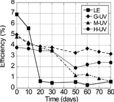
Figure 1-17 Long-term behavior of the solar-to-electricity energy conversion efficiency of the DSSCs employing the liquid electrolyte (LE), PHSMI-g- Jeffamine (G-UV), Jeffamine–PHSMA (M-UV), and PHSMA (H-UV) electrolytes after UV irradiation of 360
J/cm2………... 33
Figure 1-18 Electric circuit system of water-based dye-sensitized solar
cell……….. 35
Figure 1-19 Power conversion efficiency and short-circuit photocurrent density (Jsc) of the DSSC with and without 0.02 M Triton X-100 and 2.2 M water.……….. 36
Figure 1-20 One sun I–V curves vs water content for water-based DSSC…. 36 Figure 1-21 Schematic depicting the local-concentration control of the
I3−/I− redox couple by the hydrogen-bonding interaction between the surfactant and the carboxyl group of the dye……… 38
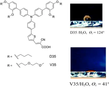
Figure 1-22 a) Molecular structures of hydrophobic dye (D35) and hydrophilic dye (V35). b) The estimation of the contact angles (θc), reveal the hydrophobicity of D35 and hydrophilicity of
V35……….. 40
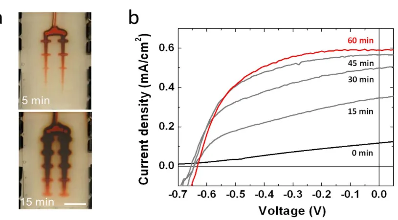
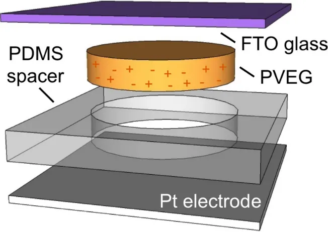
Figure 1-23 Schematic of the hydrogel photovoltaic cells (HGPVs)………….. 41 Figure 1-24 a) Images illustrating the progressive infusion of dye and
electrolytes through the gel-vascular network at 5 and 15 min after injection of the solution and the injection rate is 10 ml/min. b) I–V curves of the µ-FGPVs………
42
Figure 1-25 Fill Factor From the I-V Sweep……….. 45 Figure 1-26 Structure of the sulfonated pentablock copolymer……….. 47 Figure 1-27 Ions Sorption in sulfonated pentablock………. 49 Figure 1-28 The mechanical properties of the sulfonated pentablock
Figure 2-1 Schematic illustration of the photovoltaic cell employed in this
study………... 67
Figure 2-2 In (a, c, d), current density presented as a function of voltage for three different case studies: (a) fabrication procedure (labeled), (c) block ionomer used (see Table 1) and the cycle number for SBI2.0 (labeled), and (d) dye concentrations (labeled as [Ru(bpy)3]/[DAS] and expressed in mM) used in conjunction with SBI2.0. In all cases, the lines serve to connect the data. The inset displays the dependence of the short-circuit current density (Jsc) on open-circuit voltage (Voc) extracted from the data in (a), and the line serves as a guide for the eye. Both dye concentrations in SBI2.0 are 5 mM in (a), and the sequential dye protocol is used to generate the specimens in (c) and (d). In (b), UV-Vis absorbance spectra acquired from the SBI2.0 material upon addition of each dye and combinations thereof (labeled). All the lines connect the data, and the dotted line corresponds to an aqueous solution of Ru(bpy)3 without polymer. All data have been collected at a power density of 1 kW/m2 under AM1.5G standard light spectrum conditions……… 77 Figure 2-3 Mechanical properties measured from the hydrated SBI2.0
system alone, as well as with either Ru(bpy)3 or a mixture of both dyes (labeled). In (a), quasi-static uniaxial tensile tests provide the nominal stress as a function of strain. In (b), dynamic rheological analyses yield the frequency spectra of the storage and loss moduli (G' and G", labeled and identified by line type). Corresponding values of tan # deduced from the data in (b) are displayed in (c), and all the lines in (a) – (c) serve to connect the data. The inset in (c) shows the water uptake of SBI2.0 after addition of either Ru(bpy)3 at different concentrations (?) or an equimolar (5 mM) mixture of both dyes (dashed line), and the solid line serves as a guide for the eye… 79
in diameter and appearing as small, dark specks. A schematic illustration (d) depicts the variety of complexes that can form between the dye molecules and charged units fixed on the hydrated midblock of the ionomer (identified in the figure
legend)……… 80
Figure 3-1 TEM micrographs of SBI-2.0 cast from (a) 85TIPA and (b) THF where dark regions are Pb-stained S/sS domains and light regions are unstained T and EP domains……… 96
Figure 3-2 Different slices for TIPA casted film at different depth (a) 10, (b) 20, and (c) 30 nm……… 97 Figure 3-3 2D TEM image for SBI immersed in DI water at room
temperature………... 98
Figure 3-4 1-D SAXS scattering profile for THF-and 70 TIPA- SBI-2.0
film……….. 100
Figure 3-5 The photocurrent density- voltage (J_V) curves of hydrogel elastomer photovoltaic (HGEPV) cell prepared by using 70 TIPA under 1 kW/m2(AM 1.5 G) irradiation at tow different dyes
concentration……… 102
Figure 3-6 a) Shows the photocurrent density –voltage characteristics, (b) 1-D SAXS scattering profile for SBI-2.0 films casted from different toluene concentration………... 104
Figure 3-7 a) The photocurrent density- voltage (J-V) curves of hydrogel elastomer photovoltaic (HGEPV) cell prepared by using 70 TIP SBI-2.0-TIPA Solvent annealing films under 1 kW/m2(AM 1.5 G) irradiation at tow different dyes concentration. b) TEM micrograph of an SBI-2.0 film cast from THF and subsequently vapor annealed using THF as the annealing solvent. Dark regions correspond to Pb-stained S/sS domains whereas light regions indicated unstained T and EP domains. (c) 1-D SAXS scattering profile (right) for THF vapor annealed SBI-2.0 films initially cast from 85TIPA and THF……… 107
Figure 3-9 Shows thickness effect on photovoltaic performance. The inset shows 5 mM Das in water solution at different thickness, and the dolid line serves as a guide for the eye……….. 111
Figure 3-10 Stress-strain curves of 70TIPA films with wet state, and
Ru(bpy)3………. 113
Figure 4-1 Schematic illustration of the QS-DSSC using Sulfonated block ionomer used in this study……….. 126
Figure 4-2 a) Cross-section SEM image of QS-DSSC with SBI-THF-HI 30 iodolyte. b) Shows relatively constant elemental concentrations within each respective domain……….. 129
Figure 4-3 1-D SAXS scattering profile for SBI 2.0- TIPA film and SBI 2.0 TIPA with ionic liquid (HI-30)……….. 130
Figure 4-4 a) The J_V curve of in situ gelation of SBI-THF solution and iodolyte (HI-30) with different degree of sulfonation using N 719 sensitizer under AM 11.5 illumination. b) IPCE Spectra of devices assembled with different degree of sulfonation…………. 132
Figure 4-5 Schematic represent the morphology of SBI with different degree of sulfonation and the liquid electrolyte in the ionic
domains………. 132
Figure 4-6 The chemical structures of the three different dyes that used in
this study……… 134
Figure 4-7 J-V curve of the QS-DSSC with SBI 2.0- THF and different
dyes……… 136
Figure 4-8 J-V curve of the QS-DSSC with SBI 2.0- TIPA and different
dyes……… 136
Figure 4-9 IPCE spectra of the QS-DSSC sensitized with N 719 and SBI cast from solvents differing in polarity……….. 137 Figure 4-10 IPCE spectra of the QS-DSSC sensitized with HD-15 and SBI
cast from solvents differing in polarity……….. 137 Figure 4-11 Characteristic of QS-DSSC based on SBI2.0-THF and N719
sensitizer With different PEGDME concentration under AM 1.5 illumination; a- short-circuit photocurrent density and solar energy conversion efficiency. b- fill factor and open-circuit
Chapter 1
1-1 Introduction
The global effort to identify alternative and sustainable energy resources to
overcome climate change caused by petroleum-based pollution has inspired great
scientific interest. Of those considered, solar energy is one of the most promising
candidates for producing renewable and clean energy. On average ∼120,000 TW
per year of the Sun's energy reaches Earth’s surface, which is about four orders of
magnitude larger than the current rate of the total power consumption of the world.1 Solar cells, also called photovoltaic cells, transform light into electricity through the
use of different materials. There are many avenues to produce solar energy, such as
amorphous or crystalline silicon cells, thin film technology, organic photovoltaics
(OPV), and hybrid cells including dye-sensitized solar cells (DSSCs). Tremendous
research efforts have been devoted to constructing lightweight, inexpensive,
environmentally friendly, and flexible photovoltaics.
Crystalline silicon (c-Si) dominates the market today, with thin-film technologies
based on cadmium-telluride (CdTe), copper–indium–gallium–selenide (CIGS) and
silicon possessing only 10% of the market.2 However, c-Si, which possesses a high PV efficiency, costs significantly more than amorphous-Si due to expensive
manufacturing considerations. On the other hand, thin-film silicon devices based on
either amorphous silicon (a-Si:H) or nanocrystalline silicon are less expensive but
have more defects than c-Si and suffers from performance degradation upon light
soaking which lowers the efficiency compare to c-Si.3
The lack of viable alternatives to silicon opens the door for organic materials to be
been devoted to organic photovoltaic (OPV) cells since the late 1970s. Continued
interest in using organic rather than inorganic materials reflects several key
advantages: they are lightweight, inexpensive, mechanically robust, flexible, and
environmentally friendly.4 A major difference between organic and inorganic solar cells is in their operational mechanisms.5 In an inorganic solar cell, the energy of an absorbed photon from incident light is used to excite an electron from the valence
band to the conduction band. This will generate an electron–hole pair. The key to
generating electricity is to then separate this pair and transport the electron to an
electrode. Conversely, in an organic solar cell, the electron–hole pair is bound
together and its constituents are not free to move separately. Dissociation of these
pairs can be achieved upon application of high electric fields or at the interface
between two materials with different energy levels.
Another technology for utilizing sunlight is bioelectrochemical solar energy
conversion in which artificial photosynthesis is used to produce energy.
Photosynthesis works by producing an electron-hole pair upon absorption of sunlight
to generate fuels. The electron is transferred to photosystem I, while the hole is used
to oxidize water and release hydrogen as a source of fuel.6 This can be achieved by different technologies,7 though artificial photosynthetic systems in general require dramatic improvements in efficiency and durability before they can be considered for
practical applications, which is a great challenge.8-9
A high-potential technology that has been intensively studied in the past two
decades is dye-sensitized solar cells (DSSCs). The ability of DSSCs to mimic
scientists. Unlike traditional solar cells, DSSCs are able to work successfully in
low-light conditions and are less susceptible to thermal energy loss.10 Grätzel and co-workers,11 reported the first successful cell in 1991. This cell was developed through the introduction of mesoporous titanium dioxide (TiO2). In general, DSSC
components include an electrode, a photosensitizer and an electrolyte. Each
component plays a role in the performance of the DSSC.12-13 A comparison between different types of photovoltaics in terms of efficiency is summarized in Table 1-1.14
Table 1-1. Confirmed efficiencies measured under the global AM1.5 (1000 W/m2) spectrum at 25°C. AIST= Japanese national institute of advanced industrial science and technology.
Classification Efficiency %
Area (cm2)
Voc
(V)
Jsc
(mA/cm2) Fill factor %
Test center Si (crystalline) 25.6±0.5 143.7 0.74 41.8 82.7 AIST
Si (AMORPHOUS) 10.2±0.3 1.001 0.89 16.36 69.8 AIST
Organic thin film 11.0±0.3 .993 0.79 19.40 71.4 AIST
DSSC 11.9±0.4 1.005 0.74 22.47 71.2 AIST
Candidate materials for photovoltaic devices that are non-toxic, low cost and
environmentally friendly are block copolymers (BCP). Block copolymers consist of
blocks of different homopolymers. A diblock copolymer is a block copolymer made of
two types of homopolymers, A and B. The existence of a covalent bond between A
nanodomains can be categorized into body-centered-cubic spheres, hexagonally
packed cylinders, bicontinuous gyroids, and lamellae as shown in Figure (1-1,a).16 These morphologies are strongly dependent on the Flory–Huggins interaction
parameter (χ), the volume fraction of the components (f), and the degree of
polymerization (N) and can be depicted on Phase diagram as the one shown in
Figure (1-1,b).
Figure 1-1. a) Different nanostructures produced by BCP self-assembly. b) Theoretical phase diagram of diblocks. Where f is the volume fraction of one component. χ is the Flory–Huggins interaction parameter and N indicates the degree of polymerization. Reproduced from reference [16].
These types of material, BCPs, have been used in organic photovoltaics (OPV)
since 1925. However, a large increase in the number of publications on this topic
has emerged in the last decade. Academic and industrial interests have heightened
the importance of BCP in photovoltaics. Between 2011-2014, the number of
Web of Science database using the keywords “block copolymer photovoltaic or solar
cell’’. BCPs have the potential to be used as donor–acceptor active layers known as
bulk heterojunctions (BHJ) in OPV,17 or as structure directors in hybrid solar cells, including dye-sensitized cells, and a combination of these two approaches by mixing
conjugated polymers and inorganic semiconductors.18-19 By narrowing the search using a key word “ block copolymer and DSSC”, we found this research can be
consider as a new emerging topic, see Figure 1-2. Using BCP just start in the last decade and showed a staidly increasing in last few years.
Figure 1-2. Number of research articles published per year in the field of block copolymers in photovoltaics. (Web of Science, search performed September 1st 2015).
In this paper, we shall begin with an overview of the mechanisms of operation and
device components. Then, reviewing the role of block copolymers in these
components, and different electrolytes that have been used. Additionally, a brief
recent success of water-based DSSCs and ionic photovoltaics will be mentioned.
Next, introducing the main photovoltaic characterization measurements. Finally, we
will highlight the sulfonated block ionomer (SBI) properties and how this material can
be applied into photovoltaics.
1-2 DSSC mechanism of operation
The conversion of the incident solar irradiation to electrical current occurs through a
four-step process:20
• Step one: As a solar photon is absorbed, an electron is excited from the
ground state of the sensitizer to its excited state.
• Step two: The excited electron is injected into the conduction band of TiO2.
• Step three: Through the electric field, the electron will be transported to the
conducting anode and re-introduced into the cell on a counter electrode.
• Last step: The electrolyte will donate electrons to the oxidized dye.
Subsequently, the oxidized species of the electrolyte is reduced and able to
Figure 1-3. Schematic of the operative sequence of dye-sensitized solar cells. Reproduced from [20].
1-3 DSSC components
DSSCs consist of a photoanode, a counter electrode, an electrolyte, and a
sensitizer. Each of these components plays a key role in the performance of the cell.
1-3-1 Photoanode (working electrode)
DSSCs have been used, 22 such as ZnO, SnO2, Nb2O5, and Zn2SnO4, but TiO2 still gives the highest efficiency.23 A targeted review comparing the most common metal oxide in DSSCs is available.24 This section will not focus on reviewing the different electrodes but rather examine the properties of TiO2 that are necessary for DSSCs.
TiO2 has advantages such as good chemical stability, commercial availability with
effectively low cost, no toxicity and good biocompatibility. TiO2 has a high refractive
index (n=2.4-2.5)23 and is used as a dye in white paint. This high refractive index provides efficient scattering of light that enhances the light absorption. In addition, in
nature, TiO2 has several crystal forms such as rutile, anatase and brookite. The
preferred structure in DSSCs is anatase (pyramid-like crystals) due to the large band
gap (3.2 compare to 3.0 for rutile). Furthermore, TiO2 has a high dielectric constant
(є = 80 for anatase), which provides good electrostatic shielding of the injected
electron from the oxidized dye molecule attached to the TiO2. This prevents electron
recombination before reduction of the dye by the redox electrolyte.4
Film morphology is known to critically affect DSSC performance due to its impact on
the electron recombination rate. Therefore, numerous efforts have been made to
optimize the morphology of the nanostructured electrode. Nanoparticles,
one-dimensional nanostructures such as nanotubes12 (Figure 1-4) and nanorods have also been used in DSSCs because electrons can easily migrate through these
structures, greatly reducing electron travel time. Moreover, these nanotubes and
nanorods have special geometries with high surface area and aspect ratios that
The introduction of a compact TiO2 under layer (~50 nm thick),25 as shown in Figure 1-5, was critical for enhancing cell performance as it reduced back recombination from the fluorine doped tin oxide (FTO) electron collector and prevented contact
between the redox couple in the electrolyte and FTO. The main layer is a ∼10 µm
thick film of mesoporous TiO2 that provides a large surface area for dye adsorption
and good electron transport to the substrate. Additionally, an ultrathin (~1 nm) and
ultrapure coating of a mesoporous layer deposited using TiCl4 treatment further
increases dye adsorption.26
Figure 1-4. (a) A cross-sectional view and a (b) top view of nanotube films prepared by anodizing Ti foil. Reproduced from [12].
More kinetic data, such as electron diffusion coefficients, electron diffusion lengths
and ionic diffusion coefficients, are needed to determine and correlate
nanostructures to optimize the photoelectrode and efficiency. Increasing both the
amount of adsorbed dye molecules and the electron transport to the FTO from the
TiO2 still remains a challenge. A review of the current state of photoelectrode
structures and DSSC performance has been published recently.27
To create a flexible photovoltaic, a plastic substrate may replace the transparent
conductive oxide glass substrate in the working electrode.13 Yamaguchi et al.28 used TiO2 pasted on ITO-coated polyethylene naphthalate (ITO-PEN) as a photoanode.
They used the press method to control the TiO2 thickness to around 6-7 µm by
applying pressure in the range from 0-190 MPa. A significant effect was observed in
photocurrent density as a result of better adhesion strength between the TiO2
particles and the ITO-PEN substrate (Figure 1-6,a). In addition, they used UV-O3
treatment to increase the hydrophilicity of the ITO-PEN surface and adhesion of TiO2
paste with substrate. Also, they placed an anti-reflection film on the outer surface of
DSSC to increase the light transmitted by the substrate, which directly improved the
cell performance. The effect of the anti-reflection film on the light transmittance is
shown in Figure (1-6,b). With these fabrication conditions, the efficiency reached
Figure 1-6. a) Relationship between the pressures applied to the TiO2 film and the plastic-substrate DSSC efficiency. b) Effect of an anti-reflective (AR) film on transmittance of ITO-PEN films. Reproduced from [28].
1-3-2 Counter electrodes
The counter electrode plays a vital role in the DSSC performance and is used to
complete the electrical circuit of the solar cell and to transfer electrons arriving from
the external circuit back to the redox electrolyte.29 The counter electrode should have a high conductivity and a high exchange current density for the reduction of the
oxidized form of the redox couple. Presently, platinum (Pt) is the optimal material for
counter electrodes since it is an excellent catalyst for triiodide (I3−) reduction, has a
low charge transfer resistance and good chemical stability against electrolytes.30 Pt can be deposited using different techniques such as sputtering, dip coating,
electrodeposition, vapor deposition and spray pyrolysis. The common method used
for lab scale DSSC fabrication is sputtering. However, dip coating is the simplest
method for Pt nanoparticle deposition, which produces platinum electrodes with
good conductivity.31
An alternative counter electrode to Pt includes carbon and carbon allotropes such as
carbon black, carbon nanotubes and graphene. A high power conversion efficiency
of 9.1% was achieved under 100 mW cm-2 light intensity by using carbon black on FTO as the counter electrode.32 A clear improvement in fill factor has been observed by increasing the carbon film thickness, as shown in Figure 1-7. By increasing the thickness of the carbon film up to 14.47 µm, the surface area and porosity (rough
morphology) are both increased, consequently creating large numbers of reduction
sites. Thus, charge transfer resistance between the electrolyte and counter electrode
(Rct) was reduced. This decrease in Rct was critical for the improvement in fill factor,
and resulted in the improved efficiency. A recent, noteworthy review discussing the
different carbonaceous materials and their uses as counter electrodes in DSSC has
been published by Poudel et al.33 Carbon and its allotropes have poor electrocatalytic activity compared to Pt, yet remain an attractive material due to their
chemical stability and low cost.
Other candidate materials for counter electrodes with low cost, high-conductivity,
good stability, and good catalytic activity for triodide reduction are conjugated
polymer composites such as, polypyrrole, polyaniline (PANI), and
poly(3,4-ethylenedioxythiophene) (PEDOT). Furthermore, conjugated polymer composites
are potentially able to eliminate the need for Pt and transparent conductive oxide
(TCO) since they are capable of functioning as both the redox catalyst and the
electrical conductor. For example, PEDOT, which has advantages such as optical
replace both the Pt and the TCO. Lee et al.34 reported a power conversion efficiency of 5.08% for PEDOT film deposited on a glass substrate by in situ polymerization.
This efficiency is similar to the 5.88% observed using a Pt/TCO electrode under the
same test conditions. Another example, Poly
[3,4-ethylenedioxythiophene:para-toluenesulfonate] (PEDOT:PTS),35 a highly conducting conjugated polymer composite, was prepared by vapor phase polymerization on plain glass. It was used
as the counter electrode in a DSSC by itself, without conductive fluorine doped tin
oxide (FTO) or tin doped indium oxide (ITO) coatings.36 A power conversion efficiency of 5.25% was reported under 100 mW cm-2.
Combining a conducting polymer with a carbonaceous material will produce an
electrolyte comparable to Pt with an electro-catalytic ability for triodide reduction
and high charge mobility. A flexible composite electrode has been fabricated by in
situ chemical polymerization of polyaniline (PANI) and flexible graphite (FG)37 to substitute for the expensive Pt counter electrode (CE) used in dye-sensitized solar
cells (DSSCs). The polymerization conditions, such as reaction time and initial
monomer concentration, have been examined to control the thickness of the PANI
film. An overall conversion efficiency of 7.36% was found due to low sheet
resistance and easy charge transfer. Also, this efficiency was comparable to 7.45%
of that with Pt electrode under the same test condition. Another group studied the
PANI nanoparticles deposited on a conducting FTO glass as a counter electrode for
DSSC.38 They found PANI nanoparticles having diameters of approximately 100 nm exhibited an overall energy conversion efficiency of 7.15%, which is higher than the
conditions. The conducting researchers discovered that increasing the surface area
of PANI electrodes while also maintaining uniform and tight attachments to FTOs
improve catalytic activity and trap liquid electrolytes in DSSCs. Consequently, the
outstanding photoelectric properties, simple preparation process and inexpensive
cost allow PANI electrodes to be impressive DSSC counter electrodes.
Figure 1-7. Effect of carbon layer thickness on parameter performances of DSSCs. Reproduced from [32].
Another successful CE has been fabricated from polypyrrole (PPy) single wall
carbon nanotube (SWCNT) complexes.39 SWCNTs are good electron acceptors, and similarly pyrroles are fairly good electron donors, therefore, at elevated
temperatures around 131 ºC, electron transport between PPy and SWCNT is easily
which can be covalently shared with a carbon atom in the conjugation structure of
SWCNT (-C=), as shown in Figure 1-8. The group used Fourier transform infrared spectrometry (FTIR) to find a band shift that verified the occurrence of covalent
interactions between PPy and SWCNT. Using PPy-2 wt%-SWCNT complex as a
counter electrode for DSSCs provides a remarkable power conversion efficiency of
8.30% in comparison with that of 6.31% from PPy-only CEs.
Figure 1-8. Proposed complexation mechanism between PPy and SWCNT. Reproduced from [39].
1-3-3 Photosensitizers
The performance of DSSCs depends mainly on the sensitizer present. Dye, when
used as a sensitizer, will absorb sunlight and transform solar energy into electrical
energy, therefore the photosensitizer possess some primary characteristics such
as:23,40
• Intense absorption in the visible and near-infrared (near-IR) regions of solar
spectra. Strong adsorption onto the oxide semiconductor surface through the
phosphates, which enhance the interaction between the dye and oxide
semiconductor;
• Highly efficient electron transfer resulting from the lowest unoccupied, molecular
orbital (LUMO) of the dye being higher than the conduction band of the oxide
semiconductor;
• Efficient regeneration and the ability to avoid electron recombination, resulting
because the dye’s oxidized state has a more positive potential than that of the
redox electrolyte;
• A resistance to aggregates formation on the oxide semiconductor surface.
Also, dyes need to be photostable and have good chemical and thermal stability.
Ruthenium (Ru) based metal complex dyes are the most prevalent sensitizers, and
the molecular structures of N3, N719, and black dye are shown in Figure 1-9. Power
conversion efficiencies of more than 10% are achieved using Ru based sensitizers
due to their broad absorption spectra, suitable excited and ground state energy
levels, and good chemical stability.
One of the disadvantages of Ru based metal complex dyes is the limited absorption
in the near-infrared region of the solar spectrum. Other metal ion complexes, like
rhenium, Pt, and Cu complexes have been developed and used as sensitizers in
DSSCs. However, metal complex dyes are expensive due to the rarity of noble
metals and also their complicated synthesis. Therefore, there is a demand to
develop metal-free organic dyes. Organic dyes such as coumarin, indoline,
tetrahydroquinoline, etc. are easier to synthesize, cheaper, and are more
environmentally friendly than metal-complex dyes but characterized by narrow
absorption spectra.41 Organic dyes have the general donor-π bridge-acceptor42 configuration, schematically presented in Figure 1-10, where the π conjugated bridge is mainly based on symmetrical chromophoric units. Recently, the highest
power conversion efficiency based on pure organic dye is 10.2% by using a
dissymmetric π bridge.43 This modified organic dye structure increases the dye stabilization and decreases the recombination rate. As a result, this high efficiency is
coupled with outstanding long-term stability, as demonstrated by devices based on
an ionic liquid electrolyte.
One attempt to increase the spectral response of DSSCs is by using multiple dyes
with different absorption spectra. Co-sensitizing DSSCs with a mixture of Ru
complex (the black dye) and an organic sensitizer (D131) has achieved an efficiency
of 11%.44 A candidate sensitizer for photovoltaic applications is a porphyin-based dye, which has a significant spectral response in the near-IR and good thermal and
chemical stability. Until now, the highest recorded efficiency achieved is 12.3% by
using a cobalt (II/III) based redox couple with porphyrin based dye co-sensitized with
organic dye.45 This was a result of suppressing the electron back transfer from the oxide semiconductor to the redox couple. The benefit of the multiple-dye system is
that an electron will transfer from each dye to the electrode either independently or
will work synergistically to produce current.
Furthermore, natural dyes are another interesting DSSC sensitizer worth
exploring.20,46 These dyes can be extracted from biomaterials such as flowers, leaves, fruits, and vegetables. They are alternatives to expensive organic based
DSSCs and prepared easily when compared to ruthenium complex based dyes.
However, these natural dyes often work poorly in DSSCs due to their weak
interactions with metal oxide electrodes and low charge transfer absorption over the
entire visible range.46 Dye-sensitized solar cells with a metal-free derivative of chlorophyll,47 chlorin e6 is shown in Figure 1-11, has the highest performance with 4.3% efficiency so far reported with raw natural dyes. These solar cells revealed
wide absorption spectra in the visible light region by using co-adsorbing surfactant
agents. Three different types of cholic acids (CAs) were used as a co-adsorbing
high energy conversion efficiency of 4.3% was achieved by optimizing the TiO2
amount loaded, the electrolyte amount, and the adsorbing conditions. The
enhancement of performance is due to the suppression of the intermolecular
aggregation of the dye.
Figure 1-11. Chemical structures of chlorin e6. Reproduced from [47].
1-3-4 Electrolytes
The functions of the electrolytes in DSSCs are to regenerate the dye and to provide
an electrically conducting environment. Generally, there are certain criteria that an
electrolyte must exhibit in order to serve as a functional electrolyte for DSSCs.7,9 They include:
• The redox potential of an electrolyte should be more negative than the
oxidation potential or HOMO of the dye.
• An electrolyte should efficiently regenerate the dye after the process of dye
semiconductor. Electrolytes should not cause desorption of dye from the
photoanode.
• To avoid losses by evaporation or leakage, electrolytes should not react with
the sealant, resulting in degradation.
• The electrolyte should have minimum absorption of light compared to the dye
molecules’ absorption in the visible range.
• Finally, the electrolyte should have high electrical conductivity (~10-3 S-cm–1).
Electrolytes can be classified into three groups based on their physical state: liquid,
quasi-solid, and solid electrolyte. They contain redox ions that transfer electrons
between the photoelectrode and the counter electrode. Additionally, electrolytes
contain organic solvents that provide a medium for redox diffusion, and an additive
that modifies both the potential of the redox couple and the band shift of the
photoelectrode. Different redox ions have been tested in DSSCs, such as I−/I3−,
Br−/Br2, SCN-/SCN2, and SeCN-/SeCN248. The most prevalent redox ion used is I−/I3− due to its high performance, including reduction kinetics that slows the
recombination of I3− with conduction band electrons in the oxide semiconductor.
However, the major shortcoming of I−/I3− is the potential loss due to its high dye
reduction driving force (~0.75 V). The performance of DSSCs depends on some
physical properties of electrolytes like viscosity, dielectric constant, donor number
concentration, and redox potential.
vapor pressure, and non-flammability. When they are used in DSSCs, they serve
simultaneously as iodide sources and solvents. Their high viscosity indicates low
ionic diffusion. However, electron transfer occurs by hopping, known as the Grotthus
mechanism.49 Redox couples form well-arranged chains that assist charge transfer through the Grotthus mechanism, as shown in Figure 1-12. This type of transfer facilitates charge transport and explains the enhanced solar efficiency. Grätzel and
coworkers first utilized methyl-‐‑hexyl-‐‑imidazolium iodide (MHImI), currently the most
commonly used ionic liquid in electrochemical applications, and reported
improvement in both performance and stability of the solar cell.
Figure 1-12. Schematic drawing of the Grotthus mechanism. Reproduced from [49].
Major drawbacks for liquid electrolytes include leakage and volatility of the solvent,
ultimately affecting the stability of the DSSC. These disadvantages led to an
investigation using solid electrolytes (solid hole conductors). The basic requirements
for solid electrolyte materials consist of being p-type with valance bands that are
compatible with the HOMO level of the dye for regeneration, high hole mobility, good
conductors employed in solid-state DSSCs can be classified as either inorganic or
organic electrolytes.50
Inorganic solid electrolytes must be able to transfer holes from the sensitizer into the
TiO2, and can be deposited within the porous TiO2 layer without dissolving or
degrading the dye. Additionally, inorganic solid electrolytes need to be transparent in
the visible spectrum, or have efficient visible light absorbance. Inorganic p-type
semiconductors based on copper compounds, such as CuI, CuBr, or CuSCN are
reported to meet all of these requirements.51 Organic hole conductors have also been used in fabricating solid-state dye sensitized solar cells. These can be
classified as conductive polymers or molecular hole conductors. The first solid state
DSSC incorporating polymers was in developed in 199652 and used oligoethylene glycol methacrylate (MEO) with a power conversion efficiency of 0.49%. Hence,
many researchers work with materials that can be utilized as hole transport materials
(HTMs) to formulate approaches to improve the performance of this type of
electrolyte. Several organic and inorganic materials were designed and applied
effectively as HTMs. For example, p-type direct band gap semiconductor CsSnI2.95
F.05 doped with nonporous TiO2 and using the dye N719 showed conversion
efficiencies of up to 10.2% because of enhanced visible light absorption on the red
side of the spectrum.53 Another class of promising HTMs is organic conjugated polymers, such as poly (3, 4-ethylenedioxythiophene) (PEDOT) and poly
(3-hexylthiophene) (P3HT), which typically possess plane and continuous pathways
inside the mesopores of the TiO2 layer. Owning these structure facilities the hole
Consequently, the light-harvesting efficiency of the cell improved. The most widely
used molecular hole conductors in solid-state DSSCs are triarylamine-based
compounds, such as 2,2′,7,7′-tetrakis(N,N-di-p-methoxyphenylamine)-9,9′
-spirobifluorene (OMeTAD).
The problems arising with dye-sensitized solar cells based on solid electrolytes
include poor pore filling of the photoanode, high recombination reactions, and
unsuccessful contact with the oxide semiconductor surface as well as the counter
electrodes. However, because of their stability they continue to be promising
candidates for future research in DSSCs. Further information and a recent review of
solid-state electrolytes exist in the literature.54
Another way to eliminate the problem of volatilization of liquid electrolytes is by using
a quasi-solid electrolyte. Polymeric agents can gelate both organic solvents and
ionic liquids and transform them into quasi-solid electrolytes.55 In general, quasi-solid electrolytes have conversion efficiencies lower than liquid electrolytes. This behavior
is related to limitations in the mobility of redox couple components within the
quasi-solid electrolyte, in which charge transport occurs mainly by diffusion of molecules,
not by the Grotthus mechanism. In 2013, this claim was refuted when researchers
showed that gel electrolytes can further increase the stability of DSSCs and have
achieved photovoltaics with efficiencies higher than that of their liquid counterparts.
This improvement is attributed to the high penetration of the gel electrolytes into
TiO2 films, coupled with high ionic conductivity. Lun Chen et al.56 have reported using poly(acrylonitrile- co -vinyl acetate) (PAN-VA) copolymers as a gelators. Two
as base solutions to prepare gel-state electrolytes. The efficiency of gel electrolytes
with ACN is higher than that of the MPN solvent. The solvent effectively increases
the ionic conductivity of the electrolyte and improves the overall cell conversion
efficiency. Further improvement in the cell conversion efficiency was observed by
adding 10 wt% TiO2 nanoparticles as a filler to the gel electrolyte.57 This addition slightly reduced the recombination of photoelectrons in the electrolyte. As a result,
the current and efficiency were both increased. This step has successfully produced
quasi-solid DSSCs with efficiencies of 9.46%, higher than the liquid version that
exhibited an efficiency of 9.04%. Furthermore, combining this technique with the
use of a material with a high molar extinction coefficient, like that of heteroleptic
ruthenium complex (CYC-B11)58 instead of N719, improves the overall energy conversion efficiency up to 10.58% due to an increase in light harvesting. Finally,
(PAN-VA) was solidified by applying external pressure during the solvent
evaporation process. A solid-state DSSC with TiO2 nanoparticles as a filler and
CYC-B11 as a sensitizer was the finished product. The efficiency was 8.65%, which
is considered to be good performance but is still lower than quasi-solid DSSCs.
Another successful polymer gel electrolyte characterized as a quasi-solid state
DSSC with a conversion efficiency higher than the liquid electrolytes is
elastomeric-type copolymers consisting of poly(oxyethylene) and poly(amide-imide) (POE-PAI).59 The relationship between electrolyte concentration and photovoltaic performance
has been examined for this material. The conclusions showed that 76.8 wt%
concentration of liquid electrolyte adsorbed into the POE-PAI gave the highest
1-4 Block copolymer in DSSCs
Block copolymers possessing the ability to self-assemble are strong candidate
materials for DSSCs due to their enhanced device performance. The formation of a
high internal area with a continuously connective material having a periodicity on the
order of tens of nanometers can be exploited to increase both conductivity and light
harvesting. Therefore, they have been examined for their use in electrodes and in
both solid-state and quasi-state electrolytes.
1-4-1 Electrodes based on block copolymers
The properties of nanoparticles are linked to their dimensions, crystallinity
composition, and architecture. Additionally, the ability to control these properties
allow fine-tuning of the optical, electrical, and, catalytic characteristics of the
nanoparticles. Block copolymers have been successfully combined with TiO2
nanoparticles in DSSC systems.60 Jang et al. used a commercially-available triblock copolymer, Pluronic P123 (poly(ethylene poly(propylene
oxide)-block-poly(ethylene oxide)), as a carbon foundation in which the hydrophilic domains
contain TiO2 coated onto FTO glass,61 shown schematically in Figure 1-13. The researchers found that carbon-integrated DSSCs were characterized with higher
efficiencies than neat TiO2 due to enhancement of charge transfer and collection into
the cell. Furthermore, using nanostructured carbon-TiO2 beads improves the
structural properties of working electrodes and increases their stability. Using large
size nanoparticles (~200 nm) improves light scattering and contributes to better
Figure 1-13. The fabrication of DSSC cells containing carbon-TiO2 beads in the photoanode. Reproduced from [61].
Another group, Zheng et al. used amphiphilic star-like triblock copolymer,
poly(4-vinylpyridine)-b-poly(t-butyl acrylate)-b-polystyrene, as a carbon source.62 This triblock copolymer, having well-controlled individual block lengths, possesses a
robust star-like architecture where the inner and outer blocks, P4VP AND PS, are
hydrophilic and the center blocks, PtBA, are hydrophobic. The researchers used the
resulting architecture to produced PS-capped Au/TiO2 core/shell nanoparticles, as
Figure 1-14. Schematic of the synthesis of PS-Capped Au/TiO2 core/shell nanoparticles. Using star-like P4VP-b-PtBA-b-PS triblock copolymers forms this structure. Reproduced from reference [62].
The device efficiency improved due to the interaction of light with the Au
nanoparticles, which increased light absorption, coupled with the enhanced charge
transport supplied by the carbon present on the core/shell nanoparticle surface. For
comparison, the efficiency of DSSCs with only TiO2 is 5.67%, the Au/TiO2 layer
increase the efficiency up to 6.09%, and the highest value is 6.44%, achieved using
an Au/TiO2-c top layer.
Amphiphilic triblock poly(ethylene glycol)-block-poly(propylene glycol) block
poly(ethylene glycol), P123, used as the structure-directing agent.63 P123 plays a vital role in forming a hollow nanostructure, visualized schematically in Figure 1-15.
The device efficiency is improved by doping with rare-earth metal ions, like ytterbium
Figure 1-15. Schematic illustration of the formation of Yb3+-TiO2 HNPs. Reproduced from [63].
Lan et al. proposed that using the block copolymer, Pluronic, F-127 [poly(ethylene
oxide)106-poly(propylene oxide)70- poly(ethylene oxide)106], produced super-porous
TiO2 film which enhance the polymer gel electrolyte penetration into TiO2. The
energy conversion efficiency of approximately 7.93% is achieved, compare to 6.17%
for the mesoporous microstructure of QS-DSSC.64
As mentioned earlier, carbonaceous materials and conjugated polymers are an
alternative to produce flexible devices. Furthermore, decreasing the cost is a key
factor in commercializing any device. Recently, electropolymerized PEDOT was
used in flexible, metal-free cathodes for DSSCs with power conversion efficiencies
reaching 4.5%.65 BCPs are also candidates for the production of flexible conductive electrodes. Polystyrene-block-poly-(2-vinylpyridine) (PS-b-P2VP) diblock
copolymer-templated NiO films have been reported with the ability to be deposited in up to three
appropriate materials for building dye-sensitized photocathodes with current
densities up to 300 µA/cm2.
1-4-2 Solid-state DSSC by incorporating block copolymer
With its ability to self-organize into long-range ordered crystalline fibrils upon
spin-drying, poly(3-hexylthiophene (P3HT) copolymerized with
poly(2,5-dihexyloxy-p-phenylene)(ppp) forms an all-conjugated diblock copolymer (PPP-b-P3HT). It has
been applied as a hole transport material for the fabrication of solid-state
dye-sensitized solar cells (SS-DSSCs). The cell performance with the block copolymer
was better than the homopolymer P3HT. This result can be explained by the fact
that PPP block facilitates an intimate contact between the copolymer and the dye
molecules absorbed on the nanoporous TiO2 layer as well as increasing hole
mobility. This all-conjugated block copolymer SS-DSSC exhibits a promising power
conversion efficiency of 4.65%.67 Recent studies by Crossland et al. have demonstrated that the nanostructure formed by microphase-separated diblock
copolymers containing poly(4-fluorostyrene)-b-poly(D,L-lactide) can be used to
template hybrid solar cells with a bicontinuous gyroid morphology, as shown in
Figure 1-16. Their design, however, leads to a metallated system that is inflexible and possesses low conversion efficiency.68,69
Snaith and co-workers have conducted extensive research using block copolymers
to investigate the influence of TiO2 morphologies on solid-state DSSC efficiency.
The researchers used polyisoprene-block-ethyleneoxide (PI-b-PEO) copolymers as
structure directing agents to synthesize mesoporous TiO2. A monolithic mesoporous
films. The thickness is controlled by varying the copolymer molecular weight and the
TiO2-to-block copolymer ratio during fabrication. A mesoscopic length scale (~10
nm) solid-state electrode was achieved. This demonstrated that block copolymers
have an important role not only in the morphological aspects, but also in the
crystallization and electronic characterization, of TiO2.70 Furthermore, a solvent exchange step added to the sample preparation procedure slowed the solvent
evaporation and enhanced the solubility of the polymer and TiO2. As a result, this
allowed the utilization of the amphiphilic block copolymer (PI-b -PEO) self-assembly
to crystalize TiO2 at temperatures up to 700 °C, preventing porosity failures and
improving conductivity. The power conversion efficiency for this system reached
2.48 %.71-72
1-4-3 Block copolymer for quasi-solid state electrolytes
One solution to solvent leakage and liquid electrolyte evaporation is to utilize
quasi-solid state electrolytes in DSSCs. As mentioned earlier, different polymers have
been applied for the development of quasi-solid state DSSC (QS-DSSC)
electrolytes. In this section, examples of block copolymers applied as a gelation
agent are examined. In 2012, Hong et al. used the cross-linking properties of block
copolymers to achieve in situ gelation in a liquid electrolyte by exposing it to
ultraviolet radiation (UV).73 The solar to electric energy conversion for the liquid and gel electrolyte were comparable. However, the gel electrolyte has remarkable
Figure 1-16. Schematic represented of gyroid network replication from PFS-b-PLA templates and the assembly of hybrid solar cells. Reproduced from [69].
Jung assembled iodine-free DSSCs using doped (Cl-) polypyrrole with alkyl
imidazolium iodide as the redox couples, instead of I3-/I- redox couples in the liquid
electrolyte. Subsequently, a block copolymer poly(vinyl alcohol-b-ethylene)
(PVA-EL) was added in order to change the liquid into a gel, the conductivity of which
reached 5.56 S/cm, increasing the QS-DSSC efficiency even higher than the liquid
state without the block copolymer.74
A third example of quasi-solid state electrolytes are those made up of
PSn-b-PEOm-b-PSn block copolymers, which afforded efficiencies up to 6.7%, comparable with
liquid versions (7.3%). Block copolymers with a higher PS:PEO ratios had similar
resistance to liquid electrolytes since different volume ratios in the block copolymers
cause different morphologies. Given this phenomenon, the most favorable condition
for electrolyte diffusion was phase separation, however, this resulted in a disordered
morphology. Even though the presence of the polymer affected the Pt/electrolyte
interface by increasing counter electrode charge transfer resistance (Rct), the
lifetimes of electrons in the photoanode were comparable.75
1-5 Water-based DSSC
The demand to produce an environmentally friendly, low cost, easily fabricated and
reliable solar cell resulted in the emergence of the water-based DSSC. In 2002,
Mikoshiba et al. achieved a high conversion efficiency of up to 4.2% by applying a
buthylpyridine) with up to 10 wt% of water and without other volatile organic
solvents.76 The improved photovoltaic performance was due to the decrease in the viscosity of the electrolyte, which led to an increase in conductivity. One major
concern with aqueous electrolytes was that the high surface tension between water
and the TiO2 surface showed less hydrophilicity compared to other organic
electrolytes. As a result, this lowered the permeation of the aqueous electrolyte in
the mesoporous structure. Murakami et al. attempted to use ozone/UV post
treatment to increase the wettability of the mesoporous layer. Consequently, this
treatment increased the current density by 20% compared to the untreated device.77 Furthermore, adding water to DSSCs promoted the loss of photocurrent due to dye
detachment. The water-based DSSC is a suitable applicant for use in nontoxic and
biologically friendly solar energy devices. In 2003, Kaneko et al. used natural
products such as agarose or k-carrageenan in a water medium with the
dye-sensitized nanoporous TiO2 film in a quasi-solid DSSC to produce artificial
photosynthetic systems with energy conversion efficiency reaching 0.58%.78 In 2007, Lai et al. used different natural dyes with gold nanoparticles (Au NPs) in a
water-based DSSC schematically presented in Figure 1-18. Au NPs can act as a Schottky
barriers, promoting the efficiency of the photoelectric up to 1.49%.79 Comparing the literature published on the various components of DSSCs, water based-DSSCs hold
less interest due to a misunderstanding of the role of water in their photovoltaic
performance and stability. Kim and co-worker added a non-ionic surfactant, Triton
X-100, to the water electrolytic solution in 3-methoxpropionitrile. Triton X-100 seems to
water solubility in the organic electrolytic solution. Based on this experiment, the
TiO2 film sensitized with the N719 dye yielded a higher energy conversion efficiency
of 5.9%, compared to 5.3% without the Triton X-100 coupled with better stability as
can be seen in Figure 1-19.80 This finding opens the door to the optimization of other components in DSSCs.
Figure 1- 18. Electric circuit system of water-based dye-sensitized solar cell ( : dye). Adopted and reprinted from [79].
Law et al. successfully used two new hydrophobic Ru dyes to avoid desorption of
the dye into the water-based electrolyte. The energy conversion efficiency reached
up to 5.7% with 20% water,81 which was slightly better than with no water in the electrolyte as shown in Figure 1-20.
Figure 1-20. One sun I–V curves vs water content for water-based DSSC. Adopted and reprinted from reference [81].
Altering the redox couple is a promising research direction for the development of
water-based DSSCs. In 2012, Tian et al. introduced the water-soluble organic redox
couple 1-ethyl-3-methyl-imidazolium4-methyl-1,2,4-triazole-3-thiolate (TT−EMI+)/ 3,3′-dithiobis[4-methyl-(1,2,4)-triazole] (DTT) and used it in a device alongside
hydrophobic organic dyes. An optimal efficiency of 3.5% was obtained. This redox
couple shows higher efficiency and much better stability in water than in

![Figure 1-3. Schematic of the operative sequence of dye-sensitized solar cells. Reproduced from [20]](https://thumb-us.123doks.com/thumbv2/123dok_us/1609589.1199358/24.612.100.499.71.419/figure-schematic-operative-sequence-sensitized-solar-cells-reproduced.webp)
![Figure 1-7. Effect of carbon layer thickness on parameter performances of DSSCs. Reproduced from [32]](https://thumb-us.123doks.com/thumbv2/123dok_us/1609589.1199358/31.612.94.392.217.516/figure-effect-carbon-thickness-parameter-performances-dsscs-reproduced.webp)