ISSN(Online) : 2319-8753 ISSN (Print) : 2347-6710
I
nternational
J
ournal of
I
nnovative
R
esearch in
S
cience,
E
ngineering and
T
echnology
(An ISO 3297: 2007 Certified Organization)
Vol. 5, Issue 3, March 2016
Improvement of Voltage Stability in a
Variable Speed Wind Generation by Using
SEPIC Converter
K.Surendhirababu1, S.Ramya2
Asst. Prof, Dept of EEE, SRM University, Chennai, India1
PG Scholar, Dept of EEE, SRM University, Chennai, India2
ABSTRACT: This paper presents the results of variable speed wind power generation system using permanent magnet synchronous generator. The Sepic converters are utilized as converters for variable speed wind power generation system. The inverter is designed with space vector modulation (SVM) to reduce total harmonic distortion. Wind power generation system simulated using Matlab consisting of wind turbine, PMSG, diode rectifier, PWM controlled Sepic converter, inverter with SVM and AC load.
KEYWORDS –Variable-speed wind power generation system; Sepic converter; Permanent magnet synchronous generator.
I.INTRODUCTION
ISSN(Online) : 2319-8753 ISSN (Print) : 2347-6710
I
nternational
J
ournal of
I
nnovative
R
esearch in
S
cience,
E
ngineering and
T
echnology
(An ISO 3297: 2007 Certified Organization)
Vol. 5, Issue 3, March 2016
II. WIND POWER GENERATION SYSTEM
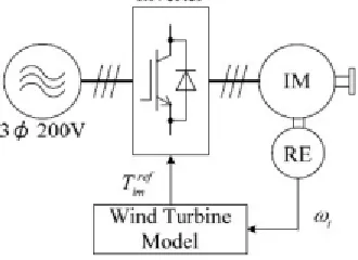
Fig 1 shows the Variable speed wind power generation system using SEPIC converter .It is not possible to operate the PMSG in the motoring mode, because the diode bridge rectifier limits the direction of DC link current .However it is not a problem, because the motoring mode is not carried out in the wind generator systems. In the meantime, the value of DC link current depends on the relationship between the induce voltage of PMSG and the DC link voltage. Therefore, it is not possible for the diode bridge rectifier to control the generator torque. Then, SEPIC converter circuit is added to improve the Variable speed range in which the diode rectifier cannot control the generator torque, the SEPIC converter can control the generator torque by controlling the DC link current.The mechanical energy from wind turbine is given to PMSG. PMSG converts mechanical energy into electrical energy. Rectifier converts AC into variable DC. Variable DC is converted into Fixed DC by using SEPIC converter. SEPIC converter switch is controlled by PWM technique .Fixed DC is converted into AC by using inverter. Inverter switches are controlled by Space vector modulation which reduces Total Harmonic Distortion (THD).Whatever be the wind speed i.e., low speed, medium speed, high speed the output voltage is maintained constant.
Fig. 1 Variable-speed wind power generation system usingSepic converter.
III. CONTROL SYSTEM
A. Wind Turbine Emulator[6]
Fig. 2 shows the basic structure of wind turbine emulator.The wind turbine model is based on the blade elementmomentum theory [7]. The wind turbine model consists of thethree dimensional table data of wind turbine characteristicsand the mechanical model considering the difference betweenreal wind turbine and induction motor. The wind velocity V0 isgiven as a condition of emulation. The windmill rotationalspeed ωr is detected with the rotary encoder (RE). The V0 andωr are used as inputs of the three dimensional table.
Fig. 2. Wind turbine emulator
ISSN(Online) : 2319-8753 ISSN (Print) : 2347-6710
I
nternational
J
ournal of
I
nnovative
R
esearch in
S
cience,
E
ngineering and
T
echnology
(An ISO 3297: 2007 Certified Organization)
Vol. 5, Issue 3, March 2016
Fig. 3. Wind turbine blade shape B. Converter Control System
Duty control system for Sepic converterFig. 4 shows the duty control system for boost converter.The change of wind velocity includes the ranges of low windvelocity, middle wind velocity, and high wind velocity. Forthe low wind velocity, the duty control system adjusts the DClink current which corresponds to the generator torquenecessary for controlling the windmill speed, by controllingthe boost converter. The DC link voltage is maintained atvoltage 100V necessary for the system interconnection by theinverter, when the duty control system is on. Duty becomes 0,because the DC link voltage is maintained at 100V by theinverter, when the windmill speed rises, and when the linevoltage of PMSG becomes over 100V. The operating range iscorrespondent to middle wind velocity, and only therectification using the reactor and diode bridge rectifier iscarried out.
Fig. 4. Duty ratio control system.
C. Inverter Control System
Space vector modulation technique is used to control the inverter. Compared to SPWM the Total Harmonic Distortion (THD) and Lower Order harmonics(LOH) contents are decreased in SVPWM.It is known that the maximum value of the peak phase voltage that can be obtained from a three phase inverter with Sinusoidal Pulse Width Modulation(SPWM) technique is equal to Vdc/2.It is therefore evident that SVPWM achieves a better DC bus utilization compared to SPWM(by about 15.4%)
ISSN(Online) : 2319-8753 ISSN (Print) : 2347-6710
I
nternational
J
ournal of
I
nnovative
R
esearch in
S
cience,
E
ngineering and
T
echnology
(An ISO 3297: 2007 Certified Organization)
Vol. 5, Issue 3, March 2016
Fig. 5. Showing the various regions of modulation
At the end of the liner modulation i.e. at a MI>0.907, the reference voltage vector tip traces acircle whose radius becomes greater than that ofthe inscribed circle of the hexagon representing thevoltage vectors which can be applied in the sixsectors.
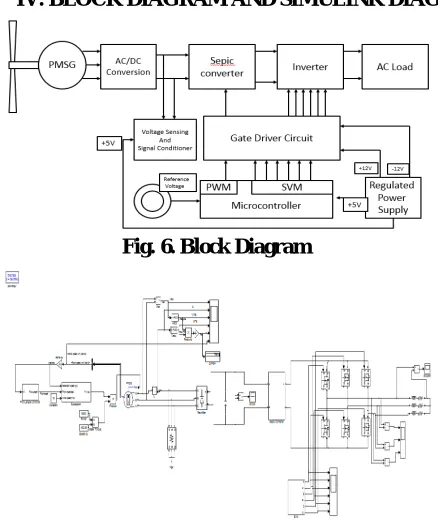
IV. BLOCK DIAGRAM AND SIMULINK DIAGRAM
Fig. 6. Block Diagram
ISSN(Online) : 2319-8753 ISSN (Print) : 2347-6710
I
nternational
J
ournal of
I
nnovative
R
esearch in
S
cience,
E
ngineering and
T
echnology
(An ISO 3297: 2007 Certified Organization)
Vol. 5, Issue 3, March 2016
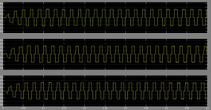
V. SIMULATION RESULTS
Fig. 8. Three phase output voltage wind speed = 7M/S (Without Converter)
Fig. 9. Three phase output voltage wind speed = 10M/S (Without Converter)
Fig. 10Three phase output voltage wind speed = 7 m/s (With Sepic Converter)
ISSN(Online) : 2319-8753 ISSN (Print) : 2347-6710
I
nternational
J
ournal of
I
nnovative
R
esearch in
S
cience,
E
ngineering and
T
echnology
(An ISO 3297: 2007 Certified Organization)
Vol. 5, Issue 3, March 2016
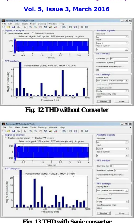
Fig. 12 THD without Converter
Fig. 13 THD with Sepic converter
V. CONCLUSION
This paper described the control strategy of variable speed wind power generation system using SEPIC converter.The simulation models of the variable speed wind generation system using SEPIC converter are implemented by using MATLAB/Simulink.The results of variable speed wind power generation without converter is compared with the results of variable speed wind power generation with SEPIC converter .Under variable wind speed condition the output of wind power is maintained constant with the help of SEPIC converter.The SEPIC converter makes the variable rectified output voltage from the PMSG to a constant DC voltage.SEPIC converter has played a keyrole in improving the voltage stability of variable speed wind power system.SpaceVectorModulation reduces Total Harmonic Distortion (THD).
REFERENCES
[1] Dong-Min Miao; Jian-Xin Shen, "Comparative study on permanent magnet synchronous generator systems with various power conversion topologies," 2013 Fourth International Conference on Power Engineering, Energy and Electrical Drives (POWERENG) pp.1738,1743, 13-17 May 2013.
[2] Ming Yin; Gengyin Li; Ming Zhou; Chengyong Zhao, "Modeling of the Wind Turbine with a Permanent Magnet Synchronous Generator for Integration," Power Engineering Society General Meeting, 2007. IEEE , pp.1,6, 24-28 June 2007.
[3] Slootweg, J.G.; Kling, W.L., "Aggregated modelling of wind parks in power system dynamics simulations," Power Tech Conference Proceedings, 2003 IEEE Bologna , vol.3, pp.6, 23-26 June 2003.
ISSN(Online) : 2319-8753 ISSN (Print) : 2347-6710
I
nternational
J
ournal of
I
nnovative
R
esearch in
S
cience,
E
ngineering and
T
echnology
(An ISO 3297: 2007 Certified Organization)
Vol. 5, Issue 3, March 2016
[5] Xia, Y.; Ahmed, K.H.; Williams, B.W., "A New Maximum Power Point Tracking Technique for Permanent Magnet Synchronous Generator Based Wind Energy Conversion System," IEEE Transactions on ,Power Electronics, vol.26, no.12, pp.3609,3620, Dec. 2011.
[6] Sharma, S.; Singh, B., "Control of permanent magnet synchronous generator-based stand-alone wind energy conversion system," Power Electronics, IET , vol.5, no.8, pp.1519,1526, September 2012.
[7] Wai, R.-J.; Lin, C.Y.; Chang, Y. -R, "Novel maximum-power-extraction algorithm for PMSG wind generation system," Electric Power Applications, IET , vol.1, no.2, pp.275,283, March 2007.
[8] Koutroulis, E.; Kalaitzakis, K., "Design of a maximum power tracking system for wind-energy-conversion applications," IEEE Transactions on , Industrial Electronics, vol.53, no.2, pp.486,494, April 2006.
[9] Busawon, K.; Dodson, L.; Jovanovic, M., "Estimation of the power coefficient in a wind conversion system," 44th IEEE Conference on Decision and Control and European Control Conference. CDC-ECC '05. pp.3450-3455, 12-15 Dec. 2005
[10] Thongam, J.S.; Bouchard, P.; Beguenane, R.; Okou, A.F.; Merabet, A., "Control of variable speed wind energy conversion system using a wind speed sensorless optimum speed MPPT control method," IECON 2011 - 37th Annual Conference on IEEE Industrial Electronics Society , pp.855,860, 7-10 Nov. 2011.
[11] Rolan, A.; Luna, A.; Vazquez, G.; Aguilar, D.; Azevedo, G., "Modeling of a variable speed wind turbine with a Permanent Magnet Synchronous Generator," IEEE International Symposium on Industrial Electronics ISIE, pp.734-739, 5-8 July 2009.
[12] Lopez-Ortiz, E.N.; Campos-Gaona, D.; Moreno-Goytia, E.L., "Modelling of a wind turbine with permanent magnet synchronous generator," North American Power Symposium (NAPS), 2012, pp.1,6, 9-11 Sept. 2012