Page 1 of 18
On the Anisotropic Mechanical Properties of Selective
Laser Melted Stainless Steel
Leonhard Hitzler 1,*, Johann Hirsch 2, Burkhard Heine 2, Markus Merkel 2, Wayne Hall 1, Andreas Öchsner 1
1 Griffith School of Engineering, Griffith University, Gold Coast Campus, Southport 4222, Australia
2 Aalen University of Applied Sciences, 73430 Aalen, Germany
* Correspondence: Leonhard.Hitzler@Griffithuni.edu.au
Abstract: The thorough description of the peculiarities of additively manufactured structures represents a current challenge for aspiring freeform fabrication methods, such as the selective laser melting (SLM). All of which have an immense advantage in the fast fabrication (no special tooling or moulds required), the geometrical flexibility in the design of components, and their efficiency when only low quantities are required. However, designs demand the precise knowledge of the material properties, which in case of additively manufactured structures are anisotropic and, under certain circumstances, in addition of an inhomogeneous nature. Furthermore, these characteristics are highly dependent on the fabrication settings. Within this study, the anisotropic tensile properties of selective laser melted stainless steel (1.4404, 316L) are investigated: The Young’s modulus ranged from 148 GPa to 227 GPa, the ultimate tensile strength from 512 MPa to 699 MPa and the breaking elongation ranged, respectively, from 12% to 43%. The results were compared to related studies, in order to classify the influence of the fabrication settings. Furthermore, the influence of the chosen raw material was addressed by comparing deviations on the directional dependencies reasoned by differing microstructural developments during manufacture. Stainless steel was found to possess its maximum strength at a 45° layer versus loading offset, which is precisely where AlSi10Mg was previously reported to be at its weakest.
Keywords: Tensile Strength, Hardness, Microstructure, Grain Morphology, Epitaxial Grain Growth, Scan Strategy, Directional Dependencies
1. Introduction
Additive manufacturing (AM) methods, such as the selective laser melting (SLM), represent powerful freeform fabrication techniques. All of which have an immense advantage in the fast fabrication (no special tooling or moulds required), the geometrical flexibility in the design of components, and their efficiency, when only low quantities are required [1-3]. Since the full melting of the raw metal powder enables the generation of fully dense parts within a single production step, with mechanical properties exceeding the specifications of the conventional material, the fabrication of highly specialized components (like tools, moulds, ultra-lightweight components or medical implants) via AM is on the rise [4-7]. One
Page 2 of 18 of the major challenges is, to date, the characterization and prediction of the properties of additively manufactured structures and their linkage with the selected fabrication settings [8]. The most utilized approach to describe the manufacturing process is via the energy input of the laser beam per unit volume, commonly referred to as the energy density [9].
= [W]
ℎ [ ]× ℎ ℎ [m]× [m s⁄ ]
Unfortunately, it appears that this convenient approach via the characterization with a single number is not able to sufficiently express the entire complexity of powder-bed based AM processes, like SLM [10-12]. Thus, at this stage, a proper description of the manufacturing process still requires the listing of the individual irradiation parameters. In addition to the pure irradiation, the information of the raw metal powder, mainly its size and the distribution, is also of great importance and should not be neglected. Spierings, et al. [13] pointed out the necessity of having both small and large powder particles: Fine particles are easily molten and favour a good relative density and surface quality; whereas bigger powder particles benefit the ductility. On this note, the mechanical properties, such as hardness and tensile strength, greatly correspond with the relative density, which is, without a doubt, the most utilized characteristic to evaluate the quality of fabricated components [10]. To illustrate its importance, the aeronautic industry introduced a minimum relative density of 99% as a standardized quality requirement [14].
Page 3 of 18 Within this study, the anisotropic material properties of stainless steel are examined with destructive material tests, since the characterisation of the anisotropic material properties via non-destructive procedures was found to be inadequate [22]. Moreover, the findings of these material tests were compared with the reported results in the literature to acquire a comprehensive overview about the inherent directional dependencies and their variation amongst various machinery and irradiation settings. Special consideration is given to the scan strategy settings and the microstructural development throughout the process.
2. Methodology
2.1.Manufacturing conditions
In this study, a SLM 280HL machine (SLM Solutions GmbH, Lübeck, Germany) equipped with a 400 W Yb-fibre-laser was utilized to manufacture the specimens. It features an available build space of 280 x 280 x 320 mm³ and includes a preheating system. The selected fabrication parameters are summarized in Table 1 and brief explication is provided in Figure 1. The low carbon stainless steel type EN 1.4404, US 316L (also known as X2CrNiMo17-12-2) was chosen as the raw material, which was supplied by SLM Solutions and had the following properties; a mean particle diameter of 35.5 μm and an apparent powder density of 3.85 g/cm3 [23].
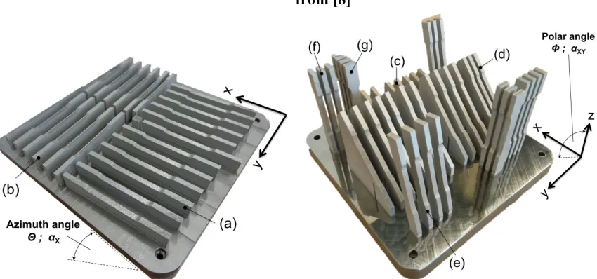
The tensile specimens were designed in accordance to the German standard DIN 50125:2009-07 as flat specimen type E 5 x 10 x 40 and fabricated in seven distinct orientations (Table 2, Figure 2), subsequently referred to as configurations (a) to (g). The azimuth angle (Θ) describes the inclination of the sample to the x-axis and the polar angle (Φ) describes the inclination in relation to the xy-plane. Since the rough as-built surface was reported to lower the tensile strength, the samples were fabricated with an oversize of 0.4 mm in width and thickness and milled to their final shape [17,24]. Detailed studies on the effects of the positioning and inclination on the as-built surface roughness can be found elsewhere [23,25].
Table 1: Parameter sets utilized for irradiation in SLM for the processing of 1.4404; see description of the parameters and the setup in Figure 1
Parameter set Scan speed [mm/s]
Laser power [W]
Hatch distance [mm]
Rotation angle increment [°]
Energy density [J/mm3]
Contour 400 100 0.09 - 92.6
Core 800 200 0.12 33 69.4
Final layer 400 300 0.1 - 250.0
Support 875 200 - - -
Common
Layer thickness of 30μm Mounting plate temperature of 200°C
Nitrogen is employed as the inert gas Contour is irradiated first, followed by the core,
Page 4 of 18 Table 2: Summary of positioning details for all considered configurations, grouping of
individual manufacturing jobs and corresponding time per job
Config. Polar angle Φ ; αXY [°] Azimuth angle Θ ; αX [°] Total runtime [h]
(a) 0 0
39.5
(b) 0 90
(c) 15 0
86.5
(d) 45 0
(e) 75 0
(f) 90 0
(g) 90 90
*Slight deviations from 0° and 90° angles were introduced for the azimuth angle of the in-plane orientated configurations ((a) and (b)) to improve the recoating process by ensuring that its blade does not abruptly hit the entire edge at once.
Figure 1: Schematic depiction of the SLM process; a) the representation of the geometry via single scan tracks and layers; b) the build environment; adapted
from [8]
Figure 2: Tensile samples on the substrate plate, overview of the positioning and arrangement
Page 5 of 18 2.2.Material testing
2.2.1. Composition and density
The material composition was determined with optical emission spectrometry (Q4 TASMAN, Bruker Corp., Billerica, Massachusetts, USA) on the machined samples. Based on the determined composition and the corresponding theoretical density the relative density was obtained via the Archimedes method.
2.2.2. Hardness
Surface hardness tests were systematically conducted on the clamping areas of the as-built and machined samples. Four indentations were evaluated on each sample. The hardness measurements were undertaken with a Reicherter KF hardness tester (Reicherter Georg GmbH Co Kg, Esslingen, Germany) in accordance to the DIN EN ISO 6507-2 standard. The testing force was set to 294.1 N and the hardness was obtained in HV30.
2.2.3. Tensile testing
For the destructive material tests, a tensile testing machine (Zwick/Roell, Ulm, Germany) with an inbuilt extensometer was utilized. The maximum load for this machine and the employed load cell was 100 kN and the initial distance of the extensometer was set to 50 mm. The testing procedure was carried out in accordance to the German standard DIN EN ISO 6892-1:2009-12 with a constant crosshead speed of 5 mm/min.
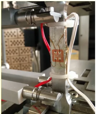
In addition, 3 out of 6 samples per configuration were equipped with an additional strain gauge (Type FCB-2-17-1L, Tokyo Sokki Kenkyujo Co., Ltd., Tokyo, Japan), comprising two individual measurement grids in perpendicular arrangement to each other (each with a size of 1.5 x 2.5 mm2). The tensile setup is depicted in detail in Figure 3.
Page 6 of 18 2.2.4. Microstructure
For investigations of the microstructure, segments were taken from the tensile samples, which were embedded in a hot mounting resin. Various grinding and mechanical polishing steps were performed to expose the metallurgical structure. The visibility of the scan track pattern and the inherent grain structure was enhanced by a subsequent etching process. High resolution images of the etched micro-sections were taken with an optical light microscope (Carl Zeiss Microscopy GmbH, Jena, Germany).
3. Results and discussion
3.1.Density and composition
The chemical composition has been examined on numerous samples of both batches and the averaged compositions are shown in Table 3. In short, the deviations amongst the two batches are negligible and are within the specifications of 1.4404. With the Archimedes method a consistent relative density greater than 99% (machined condition) was determined.
Table 3: Chemical composition of the specimens, all values in mass-percent
Config. Fe C Si Mn P S Cr Ni Mo N
(a)-(b) Bal 0.308 0.564 1.044 <0.005 0.007 16.837 11.691 2.371
-(c)-(g) Bal 0.0235 0.585 1.051 <0.005 <0.005 16.994 11.257 2.390
-DIN EN
10088-3 Bal <0.03 <1 <2 <0.045 <0.03 16.5-18.5 10-13 2-2.5 <0.1
3.2.Hardness
The hardness results were consistent along all directions and the obtained results ranged from 223 HV to 234 HV for the machined condition and, respectively, from 235 HV to 245 HV in the as-built condition (Table 4), which is in perfect agreement to the documented values in the literature (Table 5). Throughout all configurations the surface hardness in the as-built condition exhibited an increased hardness, on average around 11 HV higher.
Page 7 of 18 Table 4: Surface hardness results per configuration obtained on the machined samples
Config. Vickers hardness core [HV30] Standard deviation core [HV30] Vickers hardness contour [HV30] Standard deviation contour [HV30]
(a) 226.7 6.1 242.8 18.4
(b) 234.4 8.0 245.0 12.2
(c) 229.9 5.6 243.3 26.9
(d) 227.8 7.2 235.5 11.0
(e) 230.4 6.2 240.6 14.3
(f) 223.6 7.9 236.6 13.7
(g) 229.2 8.3 235.2 9.3
Figure 4: Orientation dependency of the surface hardness in both, the as-build and machined condition
Table 5: Hardness results 1.4404, comparison with literature and supplier specification; relative densities (≥ 99%)
Reference Vickers hardness Machine Max. laser power [W]
This work 223-245 HV30 SLM 280HL 400
Cherry, et al. [10] 220-225 HV Renishaw AM250 200
Tolosa, et al. [19] mean of 235 HV215-255 HV SLM 250 Realizer -
Kruth, et al. [26] 220-250 HV0.1 - -
Montani, et al. [27] 245 HV further specifiedPrototype, not 1000
SLM Solutions brochure [28] 209 HV - -
Sheet metal, typical value
[29-31] (212-217 HB) ~220 HV - -
3.3. Tensile strength
Page 8 of 18 in Table 6. These are drawn from six samples each, except Poisson’s ratio, which is based on three measurements each. The latter will be investigated more in detail in a separate publication, since the encountered findings are scattered within the entire possible range of Poisson’s ratio (i.e. between 0 and 0.5 [32]), with one exception even being outside this range. Thus, requiring to consider theories known from porous and composite material, which can exhibit Poisson’s ratios greater than 0.5 [33].
Similarly as in the hardness evaluation, the samples with an azimuth angle of 90° stood out. Considering the in-plane orientated configurations (i.e. (a) and (b)), the Young’s modulus differed by more than 30%, whereas the deviations in the yield strength and UTS were marginal. Interestingly, this huge dependency of Young’s modulus on the azimuth angle was only present for the samples with a polar angle of zero degree. This finding contradicts Sehrt and Witt [17], who reported that the in-plane orientation can be neglected. However, this simplification was extended; Sehrt [1] added that the in-plane tendencies correspond with the irradiation strategy and especially the rotation angle of subsequent layers. He reported that the negligible case corresponds with a 67° increment between layers, which was the only case the Young’s modulus was independent from the azimuth angle.
The breaking elongation was considerably higher for both cases with Θ = 90°, which respectively increased by 28.5% (config. (a) to (b)) and 48.5% (config. (f) to (g)). These findings coincide with those of Meier and Haberland [16], which also reported fluctuations of the breaking elongation with an varying azimuth angle.
Yet, the results of this investigation are in perfect agreement with the polar angle being the major directional dependency, influencing all tensile characteristics. The polar angle dependencies of each single characteristic are depicted in detail in the Figures 5-8 and compared with the results of related studies. Interestingly, the maxima for the Young’s modulus and the tensile strength was evident for Φ = 45°. On a side note, given this, superimposed with the azimuth angle dependency, it can be anticipated that in the case at hand the combination of Φ = 45° and Θ = 90°, which was not investigated in the present study, would yield the highest results with the utilized manufacturing settings. Fluctuations in the strength (yield and ultimate tensile strength) and, especially, in the breaking elongation by alterations of the polar angle were frequently reported. However, alterations in the linear elastic behaviour are far less investigated and the few existing studies are not in agreement. In addition to the depicted results (Figure 5), Rehme and Emmelmann [18] stated that there is no dependency of the Young’s modulus on the polar angle evident. Based on the results of this work, however, there were remarkable deviations present.
Page 9 of 18 amongst these various studies and it is also highly volatile to the individual material characteristics. The latter will be explained in detail on the microstructural development.
Proceeding with the breaking elongation, which appears to be, by far, the most volatile characteristic to alterations in the orientation (Figure 8). In this instance there is no clear tendency evident, the range of reported results scatters greatly and the progression behaviour appears random at first glance, leading to the question of how this can be the case. Clearly, to holistically clarify this question more work needs to be done. For now, the major causes for these deviations are anticipated to be inherent residual stresses and incomplete fusion between scan tracks and layers. Both resulting in a weakening of the material in a predominant direction, but depending on where the defect occurs, the weakening varies in its predominant direction. Furthermore, both of these effects are greatly influenced by the utilized laser power and the ability to control the thermal environment, e.g. by the range of available preheating temperatures, which alter the microstructural development. On a side note, Wang, et al. [34] reported that defects and pores in the as-built state can be overcome to a great extent by applying a subsequent hot isostatic pressing (HIP) treatment. Leuders, et al. [35] has found that HIP increases the ductility of 1.4404, but due to the reduction in strength and the already very good properties in the as-built state a post-heat treatment is in most cases not required.
Table 6 Averaged results for the tensile properties of 1.4404
Conf ig.
Young's modulus
E [GPa]
Yield strength
Rp0.2 [MPa]
Ultimate tensile strength Rm [MPa]
Elongation at failure
At [%]
Poisson's ratio ν [-]
Average STDEV Average STDEV Average STDEV Average STDEV Average STDEV (a) 151.01 25.56 516.51 7.16 634.43 7.39 33.24 0.57 0.444 0.031 (b) 207.57 24.22 539.47 3.29 643.67 3.25 42.74 0.82 0.155 0.014 (c) 147.87 23.59 501.32 7.70 624.65 4.36 34.09 1.12 0.479 0.058 (d) 227.35 25.12 589.89 11.86 698.98 23.65 32.56 10.17 0.203 0.024 (e) 151.43 18.80 485.65 11.93 571.23 18.63 22.84 7.27 0.558 0.020 (f) 137.78 14.25 438.60 9.69 511.99 17.95 11.76 5.38 0.453 0.005 (g) 137.83 16.25 457.21 17.29 530.22 8.09 17.46 4.42 0.170 0.085
Page 10 of 18 Figure 6: Orientation dependency of the yield strength; comparison with reported
results [4,13,16,18,19]
Figure 7: Orientation dependency of the ultimate tensile stress; comparison with reported results [4,13,16-18,37]
Page 11 of 18 3.4.Comparison AM and bulk material
Additively manufactured material generally exhibits higher strength, coupled with a reduced ductility. This holds true for the study at hand as well, bulk 1.4404 is listed with a minimum yield strength of 170 MPa and, respectively, a minimum ultimate tensile strength of 485 MPa [29,31]. Both values were exceeded by far, yet the 40% minimum breaking elongation of bulk 1.4404 is a criterion which was only achieved by one out of seven configurations. One other aspect which should be emphasised is the greatly reduced difference between the yield point and the ultimate tensile strength caused by AM [8]. In Table 7, several achieved ratios are compared with the bulk material. For safety aspects it is beneficial if the difference between these measures is large. Thus, this peculiarity is to be noted for components designed for fabrication via AM. It should be pointed out that this behaviour is not particularly negative; it simply is something which needs to be considered. Amongst materials with high strength it is very common and due to AM this behaviour is also introduced in materials which do not show this behaviour when fabricated with conventional procedures.
Table 7: Ratio between the yield point and the ultimate tensile strength for 1.4404
Reference Configurations Range Re/Rm [-] Averaged* ratio Re/Rm [-]
this work 7 0.8026-8623 0.8383
Meier and Haberland [16] 5 0.8621-0.9261 0.8889
Merkt [4] 3 0.7819-0.7877 0.7844
Rehme and Emmelmann [18] 150 0.8400-0.8877** 0.8597**
Riemer, et al. [38] 1 0.8177 -
heat treated 2 h, 650°C 0.7445 -
Spierings, et al. [13] 3 0.7941-0.8648 0.8380
Tolosa, et al. [19] 15 0.9163-0.9967 0.9565
bulk 1.4404 [29,31] - 0.35-0.37 -
* Investigated configurations are valued equally, sample sizes neglected ** only Θ = 0° and Φ = 0° - 90° considered
3.5.Comprehensive analysis of the directional dependencies and their origin
Page 12 of 18 is the case in either x- or y-direction. Applying a tensile loading under 45° to the layers results in the maximum shear stress acting parallel to the layers, thus shearing the layers apart along these embrittled areas, which are rich in Si segregations.
Considering the microstructure of 1.4404, there are no obstacles for ongoing grain growth. Thus, subsequent heat inputs, i.e. due to the neighbouring scan track or subsequent layer being generated, the grains of the already solidified materials become altered by the secondary heat input [38]. This behaviour is commonly referred to as epitaxial grain growth, describing the tendency of needle-like grain growth towards the heat source [41,42]. Due to this tendency, the grains of 1.4404 grew through the individual layers (in direction of the heat source), causing an interlocking of the individual layers (Figure 9). This interlock occurs in all directions, i.e. through layers and also through neighbouring scan tracks. Since the scan track direction is altered between layers this interlocking mechanism can be seen best in the build-up direction. An exemplified depiction of these underlying mechanisms is depicted in Figure 10 and a direct comparison of the obtained polar angle dependencies is provided as well, which clearly points out the resulting opposing, material dependent, progressions. Further examples for the material dependency on the development of directional anisotropies in AM are found in the literature. In the work of Sehrt [1] it was seen that the NiCr alloy (Hastelloy X) developed a more emphasised polar angle dependency as the stainless steel GP1 did. The results of Spierings, et al. [43] on a AlMgSc alloy (Scalmalloy) suggested that for this material the polar angle dependency can be neglected entirely, since the reported deviations are below 3.4%. Given this, there cannot be a true generalized statement on the inherent anisotropic character of AM fabricated components, at the least differentiations on the underlying material have to be made.
Page 13 of 18 directions. In this study the allowed range of possible track vectors was 90°, which limits the possible track vector range to ± 45° with the track vectors always pointing in negative y-direction (opposed to the inert gas stream), which respectively results in the lower increment boarder at 135° and the upper boarder at 225° (Figure 11). With the rotation increment set to 33°, the sequence of track vectors and scan track vector angles, as outlined in Table 8, arises. Starting at the lower border of the limitation window as the initial track vector direction, with the scan track vectors placed in altering perpendicular directions. The track vector direction is continuously changed by constantly adding the rotation increment after every layer, until the upper limitation window is exceeded. In this case, the new vector track is defined by the lower limitation window border plus the former excess. From there, the pattern continues by adding the rotation increment after every layer until the upper limit is exceeded again.
Figure 9: Microstructure of 1.4404, taken from the cross-section of the tensile samples of (i) configuration (a), (ii) configuration (b) and (iii) configuration (d)
(i) (ii)
(iii)
Page 14 of 18 Figure 10: Comparison of the microstructural characteristics of a) 1.4404 stainless steel and b) AlSi10Mg, as well as their c) strength dependency on the loading versus
layer orientation [15]
Figure 11: a) Irradiation strategy and b) limitation window; adapted from [8,45]
(a) (b)
(c)
Page 15 of 18 Table 8: Exemplary calculation of the direction of subsequent irradiation tracks
Layer Track vector angle Scan vector angle
1 [bottom increment limitation border] = 135° [track vector angle] ± 90° = 45°; 225°
2 [previous track vector angle] + [rotation angle increment] = 135° + 33° = 168° [track vector angle] ± 90° = 78°; 258°
3 [previous track vector angle] + [rotation angle increment] = 168° + 33° = 201° [track vector angle] ± 90° = 111°; 291°
4
would be outside the limitation window!, thus: [previous track vector angle] + [rotation angle increment] – [top Increment limitation border] +[bottom Increment limitation border] = 201° + 33°
- 225° + 135° = 144°
[track vector angle] ± 90° = 54°; 234°
5 [previous track vector angle] + [rotation angle increment] = 144° + 33° = 177° [track vector angle] ± 90° = 87°; 267°
4. Conclusion
In this study, the peculiarities of additively manufactured material were addressed on the example of stainless steel. It was shown that homogeneous structures can be fabricated and preheating temperatures of up to 200°C do not cause location dependent alteration of the microstructure. The scan strategy was found to massively influence the material characteristics and even simple precautions, such as limiting the irradiation pathways to avoid possible interactions between emerging particles with the laser beam, promote inherent directional dependencies. In addition, the general rule of higher strength occurring in a parallel layer to loading direction, in comparison to the perpendicular layer to loading scenario, was proven accurate. However, the progression of the mechanical characteristics with altering the inclination between the loading and the layers differed and was shown to be highly material dependent. Stainless steel exhibited its peak strength and maximum Young’s modulus under a 45° offset between the layer and loading direction, whereas the aluminium-silicium alloy AlSi10Mg revealed the lowest strength in this instance. In regard to the breaking elongation, the tested specimen showed a noteworthy drop in ductility past an inclination offset of 45°. Considering the disparate tendencies found in related studies, it can be concluded that the orientation dependency of the ductility in AM is, to date, not fully understood and further in-depth investigations need to be undertaken.
Acknowledgement
Sincere appreciation to Michael Sedlmajer, Rene Klink, Tim Schubert, Wilfried Salzwedel, Markus Hubbel, and the IMFA research institute for the helpful support throughout the implementation and evaluation of the experiments.
References
Page 16 of 18 2. Campanelli, S.L.; Contuzzi, N.; Angelastro, A.; Ludovico, A.D. Capabilities and
performances of the selective laser melting process In New trends in technologies: Devices, computer, communication and industrial systems, Er, M.J., Ed. Sciyo: 2010. 3. Hitzler, L.; Merkel, M.; Freytag, P. Design of a subframe to integrate an electric
drivetrain in existing vehicles. Mat.-wiss. u. Werkstofftech. 2015, 46, 454-461, 10.1002/mawe.201500421.
4. Merkt, S.J. Qualifizierung von generativ gefertigten Gitterstrukturen für maßgeschneiderte Bauteilfunktionen. Dissertation, RWTH Aachen, Germany, 2015. 5. Müller-Lohmeier, K. Stahl- und Aluminiumteile: Praktische erfahrungen mit
generativem prototyping. In 3. Swiss Rapid Forum, Festo AG & Co. KG: St. Gallen, Switzerland, 2005.
6. Milovanovic, J.; Stojkovic, M.; Trajanovic, M. Rapid tooling of tyre tread ring mould using direct metal laser sintering. J. Sci. Ind. Res. 2009, 68, 1038-1042,
7. Buchbinder, D.; Meiners, W.; Brandl, E.; Palm, F.; Müller-Lohmeier, K.; Wolter, M.; Over, C.; Moll, W.; Weber, J.; Skrynecki, N., et al. Abschlussbericht - Generative Fertigung von Aluminiumbauteilen für die Serienproduktion, 01rio639a-d, bmbf; Fraunhofer ILT: Aachen, Germany, 2010.
8. Hitzler, L.; Merkel, M.; Hall, W.; Öchsner, A. A review of metal fabricated with powder-bed based additive manufacturing techniques: Process, nomenclature, materials, achievable properties, and its utilization in the medical sector. Adv. Eng. Mater. 2017, SUBMITTED FOR PUBLICATION.
9. Prashanth, K.G.; Scudino, S.; Maity, T.; Das, J.; Eckert, J. Is the energy density a reliable parameter for materials synthesis by selective laser melting? Mater. Res. Lett. 2017, 1-5, 10.1080/21663831.2017.1299808.
10. Cherry, J.A.; Davies, H.M.; Mehmood, S.; Lavery, N.P.; Brown, S.G.R.; Sienz, J. Investigation into the effect of process parameters on microstructural and physical properties of 316l stainless steel parts by selective laser melting. Int. J. Adv. Manuf. Technol. 2015, 76, 869-879, 10.1007/s00170-014-6297-2.
11. Scipioni Bertoli, U.; Wolfer, A.J.; Matthews, M.J.; Delplanque, J.-P.R.; Schoenung, J.M. On the limitations of volumetric energy density as a design parameter for selective laser melting. Mater. Des. 2017, 113, 331-340, 10.1016/j.matdes.2016.10.037.
12. Kleszczynski, S.; zur Jacobsmühlen, J.; Sehrt, J.; Witt, G. Mechanical properties of laser beam melting components depending on various process errors. In Digital product and process development systems, Kovács, G.L.; Kochan, D., Eds. Springer Berlin Heidelberg: 2013.
13. Spierings, A.B.; Herres, N.; Levy, G. Influence of the particle size distribution on surface quality and mechanical properties in am steel parts. Rapid Prototyping J. 2011, 17, 195-202, 10.1108/13552541111124770.
14. Vilaro, T.; Colin, C.; Bartout, J.D. As-fabricated and heat-treated microstructures of the ti-6al-4v alloy processed by selective laser melting. Metall. Mater. Trans. A 2011, 42A, 3190-3199, 10.1007/s11661-011-0731-y.
15. Hitzler, L.; Janousch, C.; Schanz, J.; Merkel, M.; Heine, B.; Mack, F.; Hall, W.; Öchsner, A. Direction and location dependency of selective laser melted AlSi10Mg specimens. J. Mater. Process. Technol. 2017, 243, 48-61, 10.1016/j.jmatprotec.2016.11.029.
Page 17 of 18 17. Sehrt, J.; Witt, G. Auswirkung des anisotropen Gefüges strahlgeschmolzener Bauteile
auf mechanische Eigenschaftswerte. In RTejournal, Forum für Rapid Technologie: 2009; Vol. 6.
18. Rehme, O.; Emmelmann, C. In Rapid manufacturing of lattice structures with selective laser melting, Laser-based micropackaging, San Jose, California, USA, 25.-26. January, 2006; San Jose, California, USA, p 61070K.
19. Tolosa, I.; Garciandia, F.; Zubiri, F.; Zapirain, F.; Esnaola, A. Study of mechanical properties of aisi 316 stainless steel processed by "selective laser melting", following different manufacturing strategies. Int. J. Adv. Manuf. Technol. 2010, 51, 639-647, 10.1007/s00170-010-2631-5.
20. Guan, K.; Wang, Z.; Gao, M.; Li, X.; Zeng, X. Effects of processing parameters on tensile properties of selective laser melted 304 stainless steel. Mater. Des. 2013, 50, 581-586, 10.1016/j.matdes.2013.03.056.
21. Niendorf, T.; Brenne, F.; Schaper, M. Lattice structures manufactured by SLM: On the effect of geometrical dimensions on microstructure evolution during processing. Metallurgical and Materials Transactions B 2014, 45, 1181-1185, 10.1007/s11663-014-0086-z.
22. Hitzler, L.; Janousch, C.; Schanz, J.; Merkel, M.; Mack, F.; Öchsner, A. Non-destructive evaluation of AlSi10mg prismatic samples generated by selective laser melting: Influence of manufacturing conditions. Mat.-wiss. u. Werkstofftech. 2016, 47, 564-581, 10.1002/mawe.201600532.
23. Hitzler, L.; Hirsch, J.; Merkel, M.; Hall, W.; Öchsner, A. Position dependent surface quality in selective laser melting. Mat.-wiss. u. Werkstofftech. 2017, 48, 327-334, 10.1002/mawe.201600742.
24. Zhang, D. Entwicklung des Selective Laser Melting (SLM) für Aluminumwerkstoffe. Dissertation, RWTH Aachen, Germany, 2004.
25. Hitzler, L.; Hirsch, J.; Merkel, M.; Öchsner, A. Thermal environment and inclination angle dependencies on the surface quality of selective laser melted 316L steel. Defect Diffus. Forum 2017, 372, 202-207, 10.4028/www.scientific.net/DDF.372.202.
26. Kruth, J.P.; Mercelis, P.; Van Vaerenbergh, J.; Froyen, L.; Rombouts, M. Binding mechanisms in selective laser sintering and selective laser melting. Rapid Prototyping J. 2005, 11, 26-36, 10.1108/13552540510573365.
27. Montani, M.; Demir, A.G.; Mostaed, E.; Vedani, M.; Previtali, B. Processability of pure zn and pure Fe by SLM for biodegradable metallic implant manufacturing. Rapid Prototyping J. 2017, 23, 514-523, 10.1108/rpj-08-2015-0100.
28. SLM Solutions. SLM-Metal-Powder.
http://stage.slm-solutions.com/index.php?downloads_en, accessed 16/03/2016.
29. M. Woite. Edelstahl 1.4404. http://www.woite-edelstahl.info/14404de.html, accessed 14/06/2017.
30. AZO Materials. Stainless steel - grade 316L - properties, fabrication and applications (uns s31603). http://www.azom.com/article.aspx?ArticleID=2382#, accessed 14/06/2017.
31. Atlas Steels. Grade data sheet, 316 316L 316H.
http://www.atlassteels.com.au/documents/Atlas_Grade_datasheet_316_rev_Jan_2011. pdf, accessed 14/06/2017.
32. Hibbeler, R.C. Mechanics of materials. 8 ed.; Pearson Prentice Hall: 2011, ISBN 10: 0136022308; ISBN 13: 9780136022305.
Page 18 of 18 34. Wang, Z.; Shi, Y.; Li, R.; Wei, Q.; Liu, J. Manufacturing AISI316L components via
selective laser melting coupled with hot isostatic pressing. In Advanced material science and technology, pts 1 and 2, Tan, Y.; Ju, D.Y., Eds. 2011; Vol. 675-677, pp 853-856.
35. Leuders, S.; Lieneke, T.; Lammers, S.; Tröster, T.; Niendorf, T. On the fatigue properties of metals manufactured by selective laser melting – the role of ductility. J. Mater. Res. 2014, 29, 1911-1919, 10.1557/jmr.2014.157.
36. Yadroitsev, I.; Yadroitsava, I.; Smurov, I. In Strategy of fabrication of complex shape parts based on the stability of single laser melted track, SPIE, San Francisco, California, United States, 25.-27. January, 2011; Pfleging, W.; Lu, Y.; Washio, K., Eds. San Francisco, California, United States, pp 79210C-79210C-79213.
37. Shifeng, W.; Shuai, L.; Qingsong, W.; Yan, C.; Sheng, Z.; Yusheng, S. Effect of molten pool boundaries on the mechanical properties of selective laser melting parts. J. Mater. Process. Technol. 2014, 214, 2660-2667, 10.1016/j.jmatprotec.2014.06.002. 38. Riemer, A.; Leuders, S.; Thöne, M.; Richard, H.A.; Tröster, T.; Niendorf, T. On the
fatigue crack growth behavior in 316L stainless steel manufactured by selective laser melting. Eng. Fract. Mech. 2014, 120, 15-25, 10.1016/j.engfracmech.2014.03.008. 39. Aboulkhair, N.T.; Tuck, C.; Ashcroft, I.; Maskery, I.; Everitt, N.M. On the
precipitation hardening of selective laser melted AlSi10Mg. Metallurgical and Materials Transactions A 2015, 46, 3337-3341, 10.1007/s11661-015-2980-7.
40. Tang, M.; Pistorius, P.C. Anisotropic mechanical behavior of AlSi10Mg parts produced by selective laser melting. Jom 2017, 69, 516-522, 10.1007/s11837-016-2230-5.
41. Niendorf, T.; Leuders, S.; Riemer, A.; Richard, H.A.; Tröster, T.; Schwarze, D. Highly anisotropic steel processed by selective laser melting. Metall. Mater. Trans. B 2013, 44, 794-796, 10.1007/s11663-013-9875-z.
42. Niendorf, T.; Leuders, S.; Riemer, A.; Brenne, F.; Tröster, T.; Richard, H.A.; Schwarze, D. Functionally graded alloys obtained by additive manufacturing. Adv. Eng. Mater. 2014, 16, 857-861, 10.1002/adem.201300579.
43. Spierings, A.B.; Dawson, K.; Voegtlin, M.; Palm, F.; Uggowitzer, P.J. Microstructure and mechanical properties of as-processed scandium-modified aluminium using selective laser melting. CIRP Ann. Manuf. Techn. 2016, 65, 213-216, 10.1016/j.cirp.2016.04.057.
44. Materialise NV. Slm build processor: User manual 3.0 - rev. 10-2016.