Scholarship@Western
Scholarship@Western
Electronic Thesis and Dissertation Repository
4-19-2013 12:00 AM
Micro-Mechanical Assessment of the Local Plastic Strain Invoked
Micro-Mechanical Assessment of the Local Plastic Strain Invoked
During a Splined Mandrel Flow Forming Operation
During a Splined Mandrel Flow Forming Operation
Meysam Haghshenas
The University of Western Ontario Supervisor
Dr. Robert J Klassen
The University of Western Ontario
Graduate Program in Mechanical and Materials Engineering
A thesis submitted in partial fulfillment of the requirements for the degree in Doctor of Philosophy
© Meysam Haghshenas 2013
Follow this and additional works at: https://ir.lib.uwo.ca/etd
Part of the Manufacturing Commons, Metallurgy Commons, Nanoscience and Nanotechnology Commons, and the Other Materials Science and Engineering Commons
Recommended Citation Recommended Citation
Haghshenas, Meysam, "Micro-Mechanical Assessment of the Local Plastic Strain Invoked During a Splined Mandrel Flow Forming Operation" (2013). Electronic Thesis and Dissertation Repository. 1193.
https://ir.lib.uwo.ca/etd/1193
This Dissertation/Thesis is brought to you for free and open access by Scholarship@Western. It has been accepted for inclusion in Electronic Thesis and Dissertation Repository by an authorized administrator of
i
MICRO-MECHANICAL ASSESSMENT OF THE LOCAL PLASTIC STRAIN INVOKED DURING A SPLINED MANDREL FLOW FORMING OPERATION
(Thesis format: Integrated Article)
by
Meysam Haghshenas
Graduate Program in Engineering Science Department of Mechanical & Materials Engineering
A thesis submitted in partial fulfillment of the requirements for the degree of
Doctor of Philosophy
The School of Graduate and Postdoctoral Studies Western University
London, Ontario, Canada
ii
Splined Mandrel Flow Forming (SMFF) is a metal spinning operation that involves the
application of high multiaxial compressive stress states to invoke large plastic flow in the
work piece. This allows for essentially one-step fabrication of complex internally-splined
shapes. In this research project, the equivalent plastic strain, invoked throughout bcc (1020
steel) and fcc (5052 and 6061 aluminum alloys, pure copper, and 70/30 brass) samples, that
were made by SMFF, was measured. The objective of the research were to measure the to
obtain data on the effect of microstructure and mechanical parameters on the flow
formability of ductile bcc and fcc metal work pieces. To address this objective the equivalent
plastic strain in the high strain regions of the flow formed metal parts were measured with the
use of Micro/nano-indentation hardness measurements. Also, micro/nano-indentation tests
were performed, on the same alloys the metal alloys which were used in the SMFF
experiments, to assess the effect of pre-exist plastic strain, strain rate, and deformation
volume on the operative deformation mechanisms. These parameters were found to depend
upon the microstructure and the associated deformation mechanisms.
Data from indentations tests at constant loading rate and constant strain rates on a variety
of ductile metals/alloys were used to determine the effect of dislocation type (i.e.
“statistically stored”, and “geometrically necessary”), stacking fault energy, and activation
volume. This accounts for the observed strain rate sensitivity and the depth dependence of
the indentation stress. It also affects the local strain magnitude and gradient during the
SMFF process.
This micro/nano-indentation based test technique allows one to then obtain data from
which to validate calculated equivalent plastic strain distributions derived from numerical
simulations and, for end users of a metal forming technique, allows one to understand and
quantify the mechanical properties of the formed work piece.
Keywords: Splined Mandrel Flow Forming; equivalent plastic strain;
micro/nano-indentation; FCC; BCC; Indentation stress; Indentation strain rate; Constant loading rate;
iii
The research experiments were designed and executed by the candidate. The SMFF tests
were performed at TransForm Automotive (TFA) in London, Ontario, while the indentation
tests and microstructure studies were performed at Western University. The candidate
analysed all the data which involved calculating the equivalent plastic strain, P, and indentation strain rate, ind, and correlating these parameters to SMFF operating parameters
and calculating fundamental deformation parameters like activation volume *
V , mechanical
work W, and thermal activation energy of dislocations G0.
The theories explaining the experimental data trends were obtained by discussion with
co-authors, L. Wang, J.T. Wood, and R.J. Klassen. Co-authors also edited the articles prior to
iv
have, must be paid heavily for their acquiring. They are very simplest things,
and because it takes a man's life to know them, the little new that each man gets
from life is very costly and the only heritage he has to leave.
v
I dedicate this to my father and mother,
Nowzar Haghshenas
and
Giti Yoosefi
and
My Spouse,
vi
I wish to express my sincere gratitude to my supervisor Professor Robert J. Klassen for his
time, support, guidance and ideas provided throughout this project. Without his help, the
successful completion of this thesis and the quality of work achieved would not have been
possible. His contributions and help are greatly appreciated.
I also wish to thank my past and present colleagues whom I worked with at our Micro
Mechanical testing laboratory and Western Machine Shop Services, especially Mr. Brandon
Vriens, Dr. Richard O. Oviasuyi, Dr. Vineet Bhakhri, Mr. Chris Vandelaar and all those who
have been involved with this project one way or the other for their time and support.
Last but not least, I would like to express my thanks to Ontario Center of Excellence (OCE)
and TransForm Automotive (TFA) for supporting this project, financially. Great helps and
vii
Abstract ... ii
Co-Authorship Statement... iii
Dedication ... v
Acknowledgments... vi
List of Figures ... xiii
List of Tables ... xxvii
Nomenclature ... xxviii
Chapter 1 ... 1
1.1 Introduction ... 1
1.2. Rationale for Research ... 3
1.3. Objective ... 4
1.4. Structure of Thesis ... 4
1.5. References ... 8
Chapter 2 ... 9
2.1. Process Overview... 9
2.1.1. Splined Mandrel Flow Forming (SMFF) process ... 10
2.1.2. Deformation analysis in flow forming ... 10
2.2. Flow forming parameters ... 14
2.3. Flow formability (Spinnability) ... 14
2.4. Analytical techniques for studying the flow forming process ... 18
2.5. Plastic deformation of polycrystalline metals ... 21
2.5.1. Plastic deformation by dislocation glide... 21
2.5.2. Strain hardening ... 22
viii
2.5.3.2. SFE and strain hardening rate ...30
2.5.3.3. Twinning, Strength and ductility ...30
2.5.3.4. SFE and strain rate sensitivity (m) ...31
2.5.4. Tiwnnability ... 31
2.6. Pyramidal indentation testing ... 33
2.6.1. Berkovich indenter characteristics ... 33
2.6.2. Indentation platform ... 33
2.6.3. Contact Area Changes ... 36
2.7. Interpretation of the plastic strain resulting from nano/micro–indentation ... 38
2.7.1. Representative stress ... 39
2.7.2. Representative strain ... 39
2.7.3. Representative strain rate ... 43
2.8. Indentation strain rate and stress ... 43
2.8.1. Constant load rate tests (CLR) ... 43
2.8.2. Constant strain rate (CSR) tests ... 44
2.9. Indentation size effect ... 45
2.10. Characterising thermally activated dislocation mechanisms ... 49
2.11. Conclusion ... 51
2.12. References ... 52
Chapter 3 ... 59
3.1. Plastic strain distribution during splined-mandrel flow forming ... 59
3.1.1. Introduction... 60
3.1.2. Experimental procedure ... 61
ix
3.1.3.2. Analysis of the grain shape in flow formed parts ...74
3.1.4. Conclusions ... 78
3.1.5. Acknowledgements... 79
3.1.6. References... 80
3.2. Investigation of strain-hardening rate on splined mandrel flow forming of 5052 and 6061 aluminum alloys ... 81
3.2.1. Introduction... 81
3.2.2. Experimental procedure ... 83
3.2.3. Results ... 85
3.2.3.1. Effect of SMFF on the response ...85
3.2.3.2. Local plastic strain resulting from SMFF ...87
3.2.4. Discussion ... 94
3.2.4.1. Local plastic strain and plastic strain gradients ...94
3.2.4.2. Grain-to-grain variations in the local plastic strain ...95
3.2.5. Conclusion ... 98
3.2.6. References... 100
3.3. Effect of strain-hardening rate on the grain-to-grain variability of local plastic strain in spin-formed fcc metals ... 102
3.3.1. Introduction... 102
3.3.2. Experimental procedure ... 103
3.3.2.1. Correlation of indentation hardness with equivalent plastic strain ...103
3.3.2.2. Assessing the strain-hardening rate ...104
3.3.3. Results ... 105
x
3.3.3.3. Local plastic strain resulting from SMFF of the different fcc metals ...113
3.3.4. Discussion ... 114
3.3.4.1. Effect of work-hardening rate on the maximum local p ...114
3.3.4.2. Effect of work-hardening rate on the grain-to-grain variation in equivalent plastic strain ...120
3.3.4.3 Understanding the effect of strain-hardening rate on the local equivalent plastic strain ...121
3.3.5. Summary ... 122
3.3.6. References... 124
Chapter 4 ... 125
4.1. Depth dependence and strain rate sensitivity of the indentation stress of the 6061 aluminium alloy ... 126
4.1.1 Introduction... 127
4.1.2. Experimental procedure ... 127
4.1.2.1. Test material ...127
4.1.2.2. Indentation tests ...128
4.1.2.3. Calculation of the projected area function of the indentation ...128
4.1.3. Results ... 130
4.1.4. Discussion ... 137
4.1.4.1. The strain rate sensitivity of indentation stress ...137
4.1.4.2. Depth-dependent mechanism of indentation deformation ...141
4.1.5. Conclusions ... 144
xi
4.2.1. Introduction... 149
4.2.2. Experimental procedure ... 150
4.2.3. Results ... 153
4.2.3.1. Effect of P P on the indentation P–h curves...153
4.2.3.2. Indentation depth dependence of ind ...155
4.2.3.3. Strain rate sensitivity of ind ...156
4.2.4. Discussion ... 159
4.2.4.1. Depth dependency of indentation deformation ...159
4.2.4.2. Haasen plot activation analyses ...163
4.2.4.3. Role of twins in the indentation deformation process ...167
4.2.5. Conclusions ... 169
4.2.6. References... 170
4.3. Microindentation-based assessment of the dependence of the geometrically necessary dislocation upon depth and strain rate ... 172
4.3.1. Introduction... 173
4.3.2. Experimental procedure ... 174
4.3.3. Results ... 175
4.3.3.1. Indentation load–depth (P–h) plots...175
4.3.3.2. Indentation stress, ind, versus indentation depth, h ...176
4.3.3.3. Indentation strain rate, ind, versus indentation depth, h ...180
4.3.3.4. Indentation stress, ind, versus indentation strain rate, ind ...181
xii
4.3.6. References... 191
Chapter 5 ... 193
Chapter 6 ... 206
6.1. Conclusion ... 206
6.2. Suggestion for future work ... 208
xiii
Figure Description Page
1.1 Schematic representation of three roller flow forming process 2
2.1 Classification of spinning processes, a) conventional spinning, b)
shear spinning, c) flow forming (tube spinning). In each figure the
starting blank along with the final formed part is shown
schematically. 11
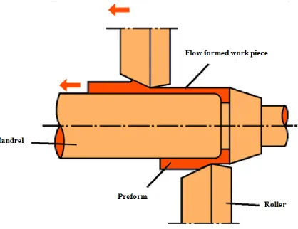
2.2 The arrangement of the forming roller, the mandrel and the work
piece during a single-roller SMFF. 12
2.3 Localized forces imposed by the forming roller during flow forming;
Pt: tangential forces, Pr: radial forces, Pz: axial forces. 12
2.4 Distribution of deformation in various directions during a flow
forming operation involving thickness reduction of the work piece:
(a) axial strain profile, (b) radial strain profile, (c) tangential strain
profile. 13
2.5 Schematic representation of small teeth area including “No-rib
zone” and “Rib zone” and the strain distribution. 14
2.6 Maximum thickness reduction (i.e. flow formability) versus tensile
reduction of area. 16
2.7 Tensile strength versus thickness reduction. 16
2.8 Sections of fractured samples from flow forming tests indicating
degree of forward reduction permissible for (A) 2024-T4, (B)
6061-T6, (C) annealed copper, (D) mild steel. 17
2.9 Maximum equivalent plastic strain incurred at the roller interface
found from fitted relationships versus thickness reduction level. The
strain increases substantially at a critical reduction level between
51.8 and 52.9% indicated by the vertical bar. 18
2.10 The variation in a) yield strength, and b) tensile strength with cold
xiv
2.12 Twin formation by progressive shear of the parent lattice. 25
2.13 Deformation in a single crystal subjected to a shear stress τ a)
deformation by slip, b) deformation by twinning in a single crystal. 26
2.14 The schematic of Hall–Petch relationship for twinning and full
dislocation slip in coarse-grained metals and alloys. τ is the shear
stress and d is the grain size. The higher slope for twinning indicates
that twinning is more difficult than the slip of full dislocations in
smaller grains. 27
2.15 Close-packed stacking sequence for fcc in a) 2D, b) 3D. 28
2.16 a) Slip in a close-packed (111) plane in an fcc lattice, b) dissociation
of a dislocation into two partial dislocations. 28
2.17 Stacking sequence with and without fault in the (111) plane of fcc
structure. 29
2.18 The engineering stress–strain curves Cu, Cu–10Zn, and Cu–30Zn
samples. 30
2.19 Schematic illustration of the hardware components of a NaoTest
platform. 35
2.20 2D and 3D schematic illustrations of a Berkovich indenter typical of
the one used in this study. 35
2.21 Schematic representation of pile-up and sink-in. Top picture is a
cross-section of the indenter at maximum load. The radius of the
projected area of contact (a) based upon displacement is an
overestimate in the case of sink-in and an over estimate for materials
that pile-up. This is easily visualized by the overhead view, where
the assumed contact area is indicated by dotted lines while the actual
contact area is indicated by the solid lines. 37
2.22 The correction parameter, c, as a function of contact depth for the
xv
as developed by Marsh and Johnson. As the hydrostatic volume
increases in size, more material undergoes plastic deformation and
the elastic–plastic boundary advances. 40
2.24 Relationship between hardness obtained from the experiment and
effective strain obtained from FE simulations in the 1010 steel. 42
2.25 Relationship between true strain and Vickers hardness for 1017
steel. 42
2.26 Geometrically necessary dislocations underneath an indenter. (a)
The material originally occupying the region of the plastic indent
has been pushed into the substrate material as extra storage of
defects. (b) A schematic view of the atomic steps on the indented
surface and the associated geometrically necessary dislocations. 47
3.1.1 (a) Geometry of the single-roller splined-mandrel flow forming
process used in this investigation; (b) flow forming sequence showing the starting work piece (Initial), the ‘cupped’ work piece
after forming passes I and II, and the fully formed work piece after
forming pass III. 63
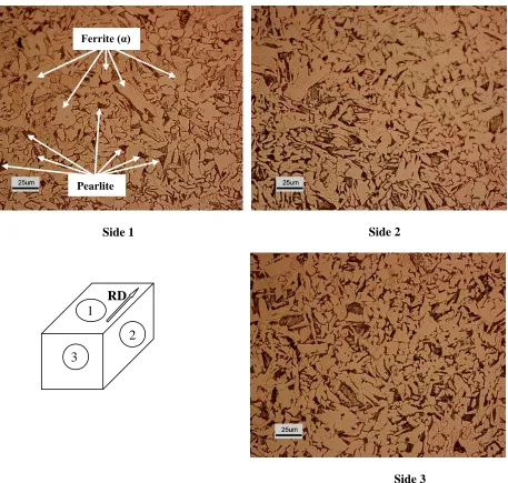
3.1.2 The equiaxed ferrite/pearlite microstructure of the 1020 steel plate
from which the discs used in this flow forming study were cut. 64
3.1.3 Flow formed parts made with different amount of thickness
reductions (TR). The small internal ribs that are studied in this
investigation can be seen in all the parts. 65
3.1.4 The location of tearing in the wall of a flow formed part that was
made with a thickness reduction greater than 51%. The tearing
occurs on the Circumferential-Radial (CR) plane directly ahead of
xvi
and the Circumferential-Radial (CR) plane across two ribs are
shown. Measurements of the indentation hardness were made in the
shaded Regions I–IV and the extent of grain elongation was
assessed in the Regions I–V. 66
3.1.6 von-Mises equivalent plastic true strain versus the Berkovich
indentation hardness for 1020 steel deformed plastically to various
thickness reduction levels by plane-strain rolling. 67
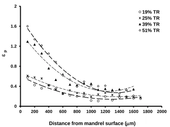
3.1.7 von-Mises equivalent plastic true strain versus distance from the
work piece/mandrel interface for different thickness reductions
levels (TR). The strain was calculated from the indentation hardness
measured along a line on the LR plane extending a distance of 1.7
mm from the top of an internal rib (Region I, Fig. 3.1.5). 69
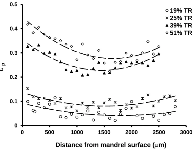
3.1.8 von-Mises equivalent plastic true strain versus distance from the
work piece/mandrel surface along a line on the LR plane extending a
distance of about 1.5 mm from immediately in front of the nose an
internal rib (Region II, Fig. 3.1.5). 70
3.1.9 von-Mises equivalent plastic true strain versus distance from the
work piece/mandrel surface at the top of an internal rib, well away
from the nose, along a line on the LR plane extending a distance of
about 2.5 mm (Region III, Fig. 3.1.5). 71
3.1.10 von-Mises equivalent plastic true strain versus distance from the
work piece/mandrel surface along a line extending a distance on the
LR plane a distance of about 1.2 mm (Region IV, Fig. 3.1.5). Plots
are shown for samples that were flow formed to work piece
xvii
forming at about 51% thickness reduction. The closed circles
represent data from the present study of an internally ribbed work
piece made by splined-mandrel flow forming while the closed
triangles represent previously reported data of a work piece that was
made by smooth-mandrel flow forming. 73
3.1.12 von-Mises equivalent plastic true strain versus distance across the
thickness on the CR plane at a location equi-distant between two
internal ribs. The part was made by single-roller flow forming
process involving a 51% thickness reduction. 74
3.1.13 The ferrite/pearlite microstructure in different regions on the LR
plane of a flow formed part (51% thickness reduction); (a) directly
ahead of the rib, (b) directly at the nose of the internal rib and (c) at
the top of the ribs away from the nose region. 75
3.1.14 The ferrite/pearlite microstructure on the CR plane in the different
regions of adjoining ribs of a flow formed part (51% thickness
reduction). (a and c) indicate the microstructure at the leading edge
while (b and d) indicate the microstructure at the trailing edge of a
rib (with respect to the forming direction). 76
3.1.15 Scanning electron micrographs of micro-indentations made on the
polished LR sections of flow formed work pieces made at thickness
reductions of: (a) 19%, and (b) 51%. The images on the left side are
from regions near the work piece/mandrel interface while the images
on the right side are from regions near the work piece/roller
interface. 79
3.2.1 Optical micrograph of the chemically etched (Keller’s reagent)
microstructure of the as-received 6061 aluminum plate material. 83
3.2.2 Indentation hardness H versus von-Mises equivalent plastic strain
xviii
alloy and b) the 5052 aluminum alloy. 86
3.2.4 Optical images of the etched microstructure of Zones I-III of the
6061 aluminum alloy after SMFF (60% thickness reduction). The
images indicate that the maximum grain elongation, and hence the
maximum plastic strain, occurs in Zone III directly in front of the
internal rib of the work piece. 89
3.2.5 von-Mises equivalent plastic true strain versus position x through the
thickness of Zone I of samples of a) the 5052 aluminum alloy and b)
the 6061 aluminium alloy made by SMFF under various thickness
reductions. The work piece/mandrel surface is at x= 0. The trends
end at decreasing x values because the final thickness of the work
piece is reduced when the thickness reduction increases. 90
3.2.6 von-Mises equivalent plastic true strain versus position x through the
thickness of Zone II of samples of a) the 5052 aluminum alloy and
b) the 6061 aluminum alloy made by SMFF under various thickness
reductions. The work piece/mandrel surface is at x= 0. The trends
end at decreasing x values because the final thickness of the work
piece is reduced when the thickness reduction increases 91
3.2.7 von-Mises equivalent plastic true strain versus position x through the
thickness of Zone III of samples of a) the 5052 aluminum alloy and
b) the 6061 aluminium alloy made by SMFF under various thickness
reductions. The work piece /mandrel surface is at x= 0. The trends
end at decreasing x values because the final thickness of the work
xix
b) the 6061 aluminium alloy made by SMFF under various thickness
reductions. The work piece/mandrel surface is at x= 0. The trends
end at decreasing x values because the final thickness of the work
piece is reduced when the thickness reduction increases. 93
3.2.9 Histogram of the average von-Mises equivalent plastic true strain
across the thickness of the 5052 and 6061 aluminum alloy samples
that had undergone SMFF involving a thickness reduction of 60%. 94
3.2.10 Maximum von-Mises equivalent plastic true strain in Zone III versus
thickness reduction for the 5052 and 6061 aluminum alloys. 96
3.2.11 Maximum von-Mises equivalent plastic true strain gradient in Zone
III versus thickness reduction for the 5052 and 6061 aluminum
alloys. 96
3.2.12 Average variance of the von-Mises equivalent plastic true strain in
Zone III versus thickness reduction for the 5052 and 6061 aluminum
alloys. 97
3.2.13 High magnification optical image of the etched microstructure near
the work piece/mandrel edge in Zone II of an indented 6061
aluminum SMFF sample. The indentations are of a size less than
the grain size indicating that variations in the measured may be due
to grain-to grain variation in the plastic flow of the alloy. 99
3.3.1 Indentation hardness H versus von-Mises equivalent plastic strain,
for both the pure copper and the 70/30 brass (solid-fill data points)
and the 5052 and 6061 aluminum alloys. 104
3.3.2 Optical micrographs of the chemically etched microstructure of the
as-received annealed a) pure copper, and b) 70/30 brass. The size of
the grains and the annealing twins are clearly larger in the 70/30
xx
rib away from the nose region, (b) directly at the nose of the internal
rib and (c) directly ahead of the rib. 107, 108
3.3.4 SMFF (60% thickness reduction) 70/30 brass microstructure in
different regions of the mid-plane plane of an internal rib (a) at the
top of the rib away from the nose region, (b) directly at the nose of
the internal rib and (c) directly ahead of the rib. 108, 109
3.3.5 Optical micrographs of the deformed microstructure in Zone III at
the mid-thickness of SMFF parts (60% thickness reduction) before
and after indentation of a) 70/30 brass, showing both deformation
twins and dislocation slip steps with considerable grain-to-grain
variability, and b) pure copper, showing no deformation twins and
extensive dislocation slip with much less grain-to-grain variability. 101-112
3.3.6 The logarithmic plot of the uni-axial tensile true stress versus true
strain of the as-received annealed brass, copper, 5052, and 6061
aluminum alloys. 113
3.3.7 von-Mises equivalent plastic true strain versus position x through the
thickness of Zone I of samples of (a) pure copper and (b) 70/30
brass made by SMFF under various thickness reductions. The work
piece mandrel surface is at x= 0. The trends end at decreasing x
values because the final thickness of the work piece is reduced when
the thickness reduction increases. 115
3.3.8 von-Mises equivalent plastic true strain versus position x through the
thickness of Zone II of samples of (a) pure copper and (b) 70/30
brass made by SMFF under various thickness reductions. 116
3.3.9 von-Mises equivalent plastic true strain versus position x through the
thickness of Zone III of samples of (a) pure copper and (b) 70/30
xxi
brass made by SMFF under various thickness reductions. 118
3.3.11 Maximum von-Mises equivalent plastic true strain in Zone III versus
thickness reduction for the 70/30 brass, pure copper, 5052 and 6061
aluminum alloys. 119
3.3.12 Maximum local plastic strain in Zone III, plotted versus the
strain-hardening coefficient, n for work pieces of the four fcc metals
deformed by SMFF to different levels of thickness reduction. 119
3.3.13 The average variance of the von-Mises equivalent plastic true strain
in Zone III versus thickness reduction for the 70/30 brass, pure Cu,
5052 and 6061 aluminum alloys. 121
3.3.14 Var
p , obtained across Zone III (60% thickness reduction), plottedagainst the strain hardening coefficient n of the fcc work piece. 122
4.1.1 Schematic representation of a three-sided Berkovich pyramidal
indenter with its tip blunted to a radius of R= 500 nm. 130
4.1.2 SEM images of Berkovich indenter which was used in the present
study. The radius of the indenter tip is 500 nm (Top view and side
view). . 131
4.1.3 Indentation force versus indentation depth curves for the 6061
aluminum alloy test material, indented at four loading rates, in the
(a) 6061-O, (b) 6061-T4, and (c) 6061-T6 thermal conditions. 132, 133
4.1.4 Average indentation stress versus indentation depth for the 6061
aluminum alloy test material, indented at four loading rates, in the
(a) 6061-O, (b) 6061-T4, and (c) 6061-T6 thermal conditions. 134, 135
4.1.5 Apparent average indentation strain rate versus indentation depth h
for the 6061 aluminum alloy test material, indented at four loading
rates, in the (a) 6061-O, (b) 6061-T4, and (c) 6061-T6 thermal
xxii
T6 thermal conditions. 138
4.1.7 logarithmic plots of indentation stress versus indentation strain rate
at different indentation depths for a: 6061-O, b: 6061-T4, and c:
6061-T6 thermal conditions. 139, 140
4.1.8 The variation of the strain rate sensitivity parameter
(log ind) (log ind)
md d versus indentation depth h for the
6061-O, 6061-T4, and 6061-T6 aluminum alloys. The strain rate
sensitivity of ind clearly increases with decreasing h. 141
4.1.9 Plots of the thermal activation energy GThermal(ind) versus indentation strain rate at different indentation depths for the 6061-O,
6061-T4, and 6061-T6 thermal conditions. 143, 144
4.1.10 Variation of the apparent activation strength G0 of the obstacles
that limit dislocation glide versus indentation depth h. G0 was
taken as the value of GThermal(ind) at a very low indentation strain
rate 1
0.001 sec ind
. G0 increases with decreasing h for the three material conditions tested which suggests that the nature of the
operative dislocation/obstacle interaction is indentation depth
dependent. 145
4.2.1 Optical micrographs of the annealed 70/30 brass material. The
microstructure contains large equiaxed grains along with annealing
twins (AT). 151
4.2.2
Indentation load P versus indentation displacement h curves from
tests performed at various levels of P P from 0.005 to 1.0 sec-1 on
70/30 brass for shallow indentations (h=0.2 m) and deep
indentations (h=2.0 m) in the: a) annealed, and b) 80%
xxiii
80% cold-worked 70/30 brass indented at different values of P P.
The average indentation strain rate is fairly constant, and
approximately equal 0.5P P, across the range of indentation depth
from h = 0.2 to 2.0 m.
155 4.2.4 Average indentation stress versus indentation depth at different
strain rates for the a) annealed, and b) 80% cold-worked 70/30 brass
alloy. Error bars indicating the magnitude of the scatter in the
indentation stress across triplicate tests performed under the same
conditions is shown for the shallow and the deep indentations. 157
4.2.5
Variation in the normalized indentation stress,
cold worked annealed
ind ind
, versus indentation depth, h, for tests
performed at four levels of indentation strain rate ind. The error bars on the plots indicate the scatter in
cold worked annealed
ind ind
arising from the multiple indentation tests performed under each
condition. 158
4.2.6 Variation of indentation strain rate sensitivity parameter, m, versus
indentation depth, h, in the annealed and the 80% cold-worked
70/30 brass samples. The strain rate sensitivity of indentation stress
clearly increases with decreasing h. The error bars indicate the range
of scatter in the measured m for triplicate indentation tests
performed at each condition. 159
4.2.7 Normalized activation volume, V*/b3, versus indentation depth for
the a) annealed, and b) 80% cold-worked 70/30 brass. V*/b3 first
increases with increasing h but tends to become constant when h is
large. The error bars indicate the range of scatter in V*/b3 for
triplicate indentation tests performed at conditions of the highest and
xxiv
strain rate at different indentation depths for the (a) annealed and (b)
80% cold-worked 70/30 brass material. The error bar in each plot
indicates the typical range of scatter of ΔGThermal for triplicate
indentation tests performed under identical test conditions. 164
4.2.9 Variation of the apparent activation strength ΔG0 of obstacles that
limit the dislocation glide during indentation versus indentation
depth h for both the annealed and the 80% cold-worked 70/30 brass
materials. The data of all three tests at each strain rate have been
shown. 165
4.2.10
b2/Δa versus ind for the indentation tests performed on the (a) annealed, and (b) 80% cold-worked brass at different indentation
depths from 0.2 m to 1.8 m. 166
4.2.11
Linear relationship between ΔG0 and W' for the annealed and the
80% cold-worked 70/30 brass material. The data of all three tests at
each strain rate have been shown.
167
4.2.12 Optical micrographs of the cold-worked 70/30 brass material at two
magnifications. The microstructure contains elongated grains/twins
and mechanical twin (MT) clusters in a few grains. 168
4.3.1 Indentation load versus indentation depth for all tested materials,
(a): 1 mN/sec, (b): 10 mN/sec, (c): 100 mN/sec, and (d): 1000
mN/sec. 177, 178
4.3.2 Indentation stress versus indentation depth for all tested materials at
(a): the lowest load rate; 1 mN/sec, and (b): the highest load rate;
1000 mN/sec. 179
4.3.3 Indentation stress versus indentation depth at different loading rate
in the 70/30 brass material. For a given indentation depth, the
xxv
depth for the pure copper indented at four loading rates. ind decreases with increasing h under constant loading rate condition.
The shape of the curves is the same for the 5052 aluminum alloy and
the 70/30 brass. 181
4.3.5 Logarithmic plot of ind versus ind at loading rate of 10 mN/sec for
70/30 brass, pure copper and 5052 aluminum alloy. 182
4.3.6
GND
versus h for the lowest indentation load rate (1 mN/sec) for
three fcc materials studied 184
4.3.7 GThermal GNDs, versus indentation stress, ind for the a) 5052
aluminum, b) pure copper, and c) 70/30 brass. 186, 187
4.3.8 G0,GNDs versus SFE, reported in the literature, for the shallowest
(h= 500 to 800 nm) at different loading rates. 188
4.3.9 Normalized activation volume, * 3
V b , versus average indentation
stress, ind for tests performed between h=500-800 at the lowest
loading rate (1 mN/sec). 189
4.3.10 Normalized activation volume, * 3
V b , versus GNDs density for the
pure copper and 5052 aluminum alloys samples tested at indentation
depth h= 500-800 nm. 190
5.1 The uniaxial tensile engineering curves for as received and
SMFF’d (in axial and circumferential directions) for 1020 steel. 195
5.2 Normalized work hardening rate ( G) versus strain for 5052 and 6061 aluminum alloys. The presence of Mg solute atoms may lead
to the appearance of plastic instabilities resulting in the well-known
serrated yielding or Portevin-Le Chatelier (PLC) effect which marks
itself as steps in the G curve at strains bigger that 2%. 196
5.3 The uniaxial tensile engineering response of as received
70/30 brass and SMFF’d samples (in axial and circumferential
xxvi
and pure copper. Four distinct regions are seen in the data from the
xxvii
Table Description Page
2.1 Flow forming process variables
15
2.2 Slip Systems for Face-Centered Cubic and Body-Centered Cubic
metals
22
3.2.1 Listing of the chemical composition, uniaxial yield stress, ductility,
and strain-hardening coefficient of the 5052 and 6061 aluminum
alloys
87
3.3.1 Chemical composition, stacking fault energy, and grain size of the
four fcc metals studied in this investigation
110
xxviii
Symbols Definition
SMFF Splined Mandrel Flow Forming
FCC Face Centered Cubic
BCC Base Centered Cubic
y
Yield Stress
n Strain hardening exponent
Strain hardening rate
SFE Stacking Fault Energy
T0 Fully annealed condition
T4 Partially aged condition
T6 Fully aged condition
ind
Indentation strain rate
ind
Indentation stress
m Strain rate sensitivity
h Indentation depth
P Indentation load
P Indentation load rate
h Indentation displacement rate
GNDs Geometrically Necessary Dislocations
SSDs Statistically Stored Dislocations
r
P Radial force
t
P Tangential force
z
P Axial force
d Average grain diameter
y
k Hall-Petch equation constant
%EL Elongation percent
xxix
T
k Hall-Petch slope for twinning
S
k Hall-Petch slope for slipping
c Pile-up or Sink-in factor
ind
A Indentation projected area
V
H Vickers hardness
r
Indentation representative strain
ind
Effective average indentation shear strain rate
ILR Indentation Load Relaxation
CLR Constant Load Rate
CSR Constant Strain Rate
h* Characteristic length in the Nix/Gao model
H0 Indentation hardness for a large indentation depth
μ Elastic shear modulus
t
Total dislocation density
b Burgers vector
*
Thermal component of the stress
i
Athermal component of the stress
m
Mobile dislocations density
Frequency of atomic vibration
β Dimensionless constant
( )
Thermal
G
Thermal activation energy
T Absolute temperature
TR Thickness reduction
i
t Starting thickness
f
t Final thickness
CR Circumferential-Radial
LR Longitudinal-Radial
xxx
SEM Scanning Electron Microscope
PLC Portevin-Le Chatelier Effect
x dxdp Equivalent plastic strain gradient
max
p
Maximum equivalent plastic strain
pVar Point-to-point variation in the equivalent plastic strain
MT Mechanical twin
AT Annealing twin
( ) p xi
Predicted value of local equivalent plastic strain from the
second-order polynomials that were fitted to the data profiles
crit
h Critical indentation depth
actual
A Actual contact area
ideal
A Ideal projected area
Er The reduced elastic modulus
.
Hert
P Hertzian elastic contact force
E Young modulus
0 G
Activation strength of the deformation rate controlling obstacles
'
W
Apparent mechanical activation work
*
V Activation volume
a
1 Inverse activation area
ISE Indentation size effect
SSD
Density of geometrically necessary dislocations
GND
Density of statistically stored dislocations
Chapter 1
Overview
1.1 Introduction
Parts manufacturers, especially those in the automotive industry, are designing complex
metal components and are therefore looking for the fastest and most efficient way to
produce complex shapes.
Flow forming has gradually matured as a metal forming process for the production of
engineering parts in small to medium batch quantities in last two decades. Advantages
such as flexibility, simple tooling and low forming loads, have made the flow forming as
a promising process to optimise designs and reduce weight and cost, all of which are
vital, especially in the automotive industries.
Flow forming-made parts appear to be an attractive alternative to press formed parts
especially with its lower forming load requiring considerable smaller equipment and
more flexible tooling as compared to conventional forming processes.
Flow forming is commonly known as a process for transforming flat sheet metal blanks,
usually with axi-symmetric profiles, into hollow shapes by a tool which forces a blank
onto a mandrel, as illustrated in Fig. 1.1. The blanks are clamped rigidly against the
mandrel by means of a tailstock and the shape of the mandrel bears the final profile of the
desired product. During the process, both the mandrel and blank are rotated while the
spinning tool contacts the blank and progressively induces a change in its shape
according to the profile of the mandrel.
As the tool is applied locally on the work piece, the total forming forces are reduced
significantly compared to conventional press forming. This not only increases the
possibilities in terms of large reductions and change in shape with less complex tooling,
but also reduces the required load capacity and cost of the forming machine. In addition,
flow forming is also known to produce components with high mechanical properties and
For precision flow forming operations, typically three rollers placed with 120° design is
used. These rollers have pre-calculated radial and axial offsets between each other to
achieve necessary forming conditions. The rollers force the metal blank over a cylindrical
mandrel (smooth mandrel or splined mandrel). In the splined mandrel flow forming
(SMFF), the metal blank is forced to conform to the shape of the mandrel cylinder
including flowing into, and filling, the splines. The components fabricated in such a way
are dimensionally accurate replications of splined mandrel that require only minimal
secondary machining.
Figure 1.1: Schematic representation of three roller flow forming process.
As the use of flow forming to create internally-ribbed automotive components is a
relatively new field of manufacturing, the interrelation of various flow forming
parameters is not completely known. For example, very high local plastic strain occurs in
the steel work piece as it flows into, and fills, the mandrel splines during a flow forming
process and the tool life (particularly the life of the splined mandrel). It is essential to
optimize the flow forming process parameters in order to ensure that a high quality
product is produced without generating unnecessary tool wear.
1.2. Rationale for Research
The production of SMFF’d components with complex geometries is limited by an
industry-wide lack of knowledge of the local stress and plastic strain that arises within
these parts and within the tooling during fabrication. SMFF process produces a complex
and highly variable state of triaxial strain in the work piece with large strain gradients
occurring in the complex region of several microns from surface. This results in increased
rates of rejected parts and increased tool wear. In this research, the effect of average work
piece thickness reduction as a controllable process variable on the local stress state and plastic flow in the vicinity of a splined mandrel of SMFF’d parts made from bcc (1020
steel) and fcc (6061, and 5052 aluminum alloys, pure copper, and 70/30 brass) metal
alloys was studied. Strain hardening rate, maximum local equivalent plastic strain, and
the grain-to-grain variability in the equivalent plastic strain distribution in these parts is
considered in detail by means of micro/nanoindentation testing. The outcome of this
investigation is data that will allow the identification of practical operating bounds for the
SMFF process.
Manufacturers who plan to use SMFF need to understand the formability bounds of the
process. They therefore require empirical relations that describe work piece/mandrel
failure rates as a function of the controllable process variables and have the ability to
predict failure rates under conditions that are beyond the current conventional practice.
Measurement of the local plastic strain within the interior of thick work pieces that have
been deformed into irregular shapes, such as what occurs in SMFF, are made by post-test
sectioning of fabricated parts. The local plastic strain is then deduced from either local
changes in grain shape or local changes in indentation hardness within the part.
Non-destructive techniques such as neutron diffraction can measure the internal elastic strain
within such parts however this technique has limited spatial resolution and does not give
The aim of the present research is to assess the effects of microstructure, and associated
deformation mechanism (i.e. dislocation slip and deformation twinning) on the practical
flow formability of a metal. These mechanisms are highly dependent upon applied strain,
pre-existing plastic strain, and volume of deforming metal. The effect of these variables cannot be assessed directly from a SMFF’d sample. Thus, in this thesis considerable
micro/nano-indentation tests at various regions, depths, and strain rates to perform these
assessments are performed.
1.3. Objective
My PhD research topic is directed to obtaining a detailed understanding of the global and
the local plastic strains and failure criteria that develop during SMFF operations
involving complex mandrel shapes and tool paths performed on fcc metal alloy (6061,
and 5052 aluminum alloys, brass 70/30, and pure copper) and bcc (1020 steel) work
pieces. Micro-level plastic strain measurements performed on these work pieces under
different levels of the forming variables (i.e. mandrel rotational speed, roller feed rate,
and thickness reduction) are identified. The objectives of the project are:
Assessment of the equivalent plastic strain within the work pieces. Using
micro-indentation hardness, plastic deformation is measured at different areas of made
samples under different forming conditions.
Analysis of the effect of microstructure and mechanical parameters (yield stress (y),
rate of work hardening (), stacking fault energy, and grain shape) on the local equivalent plastic strain within a SMFF’d parts.
Consider the effect of deformation mechanisms under constant load rate and constant
strain rate during micro/nano-indentation of the metal alloys which were used in the
SMFF experiments.
1.4. Structure of Thesis
This thesis has been written following the guidelines of the School of Graduate and
Postdoctoral Studies at Western University adopting an integrated-article format. It
contains 6 chapters. Chapter 1 of the thesis includes an introduction on the splined
Chapter 2 contains a review of relevant published literature on the flow forming process
and the mechanisms of plastic flow at room temperature of the ductile fcc and bcc
materials that will be flow formed in this thesis. This chapter continues a description of
the indentation test technique and the interpretation of the plastic strain data arising from
such tests.
Chapter 3 is an integration of three published papers on the plastic strain distribution
profiles, and work hardening behaviour during splined-mandrel flow forming of bcc alloy
(1020 steel), and four fcc alloys (5052, and 6061 aluminum alloys, 70/30 brass, and pure
copper). The three papers were published in Materials & Design [1] and Materials
Science and Engineering A [2, 3]. The paper published in Materials & Design entitled “Plastic strain distribution during splined-mandrel flow forming” dispute compresses
plastic strain distribution of the 1020 steel work pieces subjected to SMFF with different
levels of average work piece thickness reduction, from 20 to 60%. A part of this work
was presented and published in the Proceedings of International Deep Drawing Research
Group (iddrg 2010), Graz, Austria [4]. The two published papers in Materials Science
and Engineering A are entitled “the investigation of strain-hardening rate on splined mandrel flow forming of 5052 and 6061 aluminum alloys” [2] and “effect of
strain-hardening rate on the grain-to-grain variability of local plastic strain in spin-formed fcc metals” [3]. In the first paper, the role of solid solution strengthening additions, i.e. Mg
in 5052 aluminum alloy, on increasing the average mechanical strength but also
increasing the extent of local plastic strain variability in aluminum alloy material
subjected to intensive plastic forming operations such as SMFF. The later article on the
SMFF of pure copper and 70/30 brass, the deformed microstructure of the formed work
pieces indicated that considerably more grain-to-grain variability in the dislocation slip
step and deformation twin densities exist in the material with a high strain-hardening rate.
These findings are of considerable importance and should be considered when assessing
the suitability of high strain forming processes for producing reliable, and homogeneous,
parts from fcc metal alloys that display high strain hardening rates.
Chapter 4 is an integration of three papers on the depth dependence and strain rate
Materials Science and Technology [5], the second paper entitled “characterization of
depth dependence of indentation stress during constant strain rate nanoindentation of 70/30 brass” was published in Materials Science and Engineering A. The third paper
entitled “Microindentation-based assessment of the dependence of the geometrically
necessary dislocation upon depth and strain rate” has been accepted in MRS 2013
proceedings.
The paper published in Materials Science and Technology investigates depth dependence
and strain rate sensitivity of indentation stress of 6061 aluminium alloy. Constant load
rate microindentation on fully annealed, partially aged (T4), and fully aged (T6) of 6061
aluminum alloy were investigated in this paper [5].
The second paper reports the results from nanoindentation tests that was performed under
constant strain rate conditions to investigate the effect of ind upon the indentation depth
dependence of ind for annealed and cold worked 70/30 brass [6]. It was observed that parameters, such as the strain rate sensitivity m, and the apparent activation energy ΔG0
showed a clear dependence upon indentation depth but the magnitude of these
parameters, which were obtained under constant strain rate conditions, were the same as
equivalent values obtained by others under constant load rate conditions. This suggests
that valid measurement of thermally-activated parameters can be obtained in common
metals by performing micro-indentation tests under constant P conditions. At any given
indentation depth, P increases with increasing the strain rate ( 0.5P P).
The last paper in chapter 4, accepted to be published at the MRS 2013 proceedings [7],
deals with the room–temperature load–controlled pyramidal microindentation tests on the
fcc annealed alloys of 70/30 brass, pure copper, and 5052 aluminum alloy samples. In
this paper, by means of Nix and Gao model, the size effect during indentation tests was
studied and the density of statistically stored dislocations (SSDs) and geometrically
necessary dislocations (GNDs) were obtained. GNDs showed an inverse relationship with
depth, h. Using an Arrhenius law, which describes the successful surmounting of an
obstacle by thermal activation of the dislocation segments, as well as the Nix/Gao model,
characteristic parameters of dislocation motion such as activation volume and activation
Chapter 5 of this thesis combines the findings from the published papers in Chapters 3
and 4 into a discussion of the effect of work hardening rate, stacking fault energy (SFE),
twinning and/or various dislocation glide mechanisms on the local grain to grain
variability in plastic strain during high strain metal forming operation (such as SMFF).
In this chapter also the strain rate sensitivity, activation volume and activation energy
(measured from Nano/Micro-indentation) of SMFF’d metal alloys are compared
discussed in detail.
The thesis ends in Chapter 6 with a short summary of the main findings and contributions
1.5. References
[1] M. Haghshenas, M. Jhaver, R.J. Klassen, J.T. Wood, Materials & Design 32 (2011)
3629.
[2] M. Haghshenas, J.T. Wood, R.J. Klassen, Materials Science and Engineering A 532
(2012) 287.
[3] M. Haghshenas, J.T. Wood, R.J. Klassen, Materials Science and Engineering A 552
(2012) 376.
[4] M. Haghshenas, J.T. Wood, R.J. Klassen, Proceedings of International Deep Drawing
Research Group (iddrg 2010), Graz, Austria, 255.
[5] M. Haghshenas, L. Wang, R.J. Klassen, Materials Science and Technology 28 (2012)
1135.
[6] M. Haghshenas, R.J. Klassen, Materials Science and Engineering A 572 (2012) 91.
[7] M. Haghshenas, R.J. Klassen, MRS 2013 symposium proceedings, Materials
Chapter 2
Review of the relevant literature
In this chapter, at first, the Splined Mandrel Flow Forming (SMFF) process is
overviewed (section 2.1). The effect of flow forming variable parameters on the finished
part under different conditions is reviewed in the Section 2.2. The concepts of flow
formability (spinnability) and analytical/experimental techniques for studying the flow
forming are reviewed in the Sections 2.3 and 2.4. In Section 2.5, the mechanisms of
plastic deformation of polycrystalline materials (i.e. slipping and twinning) are addressed.
Pyramidal indentation testing, the plastic strain resulting during nano/micro-indentation,
indentation size effects, and thermal activation of dislocations during the indentation
process are covered in Sections 2.6–2.10.
2.1. Process Overview
This section is aimed at reviewing the flow forming fabrication technique. Published
literature related to smooth mandrel flow forming is reviewed to provide an important
background for my current research on splined mandrel flow forming (SMFF).
Spinning, shear forming, and flow forming (as presented in Fig. 2.1) can all be thought of as “chipless turning” technologies because there is no material removed during the
process and, hence, metal shaping occurs exclusively by plastic deformation of the work
piece. Any ductile material can, in principal, be formed by these operations and
examples exist in the literature of such operations performed on work pieces of various
grades of steel, including stainless steel, and non-ferrous metals such as titanium,
aluminum, bronze and copper [1, 2].
Flow forming operations performed over cylindrical mandrels produce a seamless
cup-like product with very tight dimensional tolerance. A metal blank or preform is formed
over a rotating mandrel. The metal blank and the mandrel (which are locked together)
rotate, and the forming roller follows the mandrel at a preset. The large compressive
forces exerted by the rollers cause the work piece to deform plastically. The deformed
metal takes the shape of the mandrel, and proper wall thickness is achieved by control of
This forming technique offers significant advantages in comparison with other
conventional production techniques. These advantages are particularly pronounced when
components are to be produced in small or medium size batches due to lower tooling
costs than other process such as deep drawing. Localized deformation of the material
under the forming rollers also requires lower forming forces than techniques such as, for
example, deep drawing and press forming. The other advantages are [3]:
Very little wastage of material.
Excellent surface finishes.
Accurately dimensioned components.
Improved strength properties.
Components made by flow forming (tube spinning) include parts for the automotive and
aerospace industries, art objects, musical instruments and kitchenware [2]. The process is
capable of forming components of diameters ranging from 3 mm to 10 m, and thickness
of 0.4 to 25 mm [4].
2.1.1. Splined Mandrel Flow Forming (SMFF) process
SMFF is an effective technique for fabricating internally ribbed cylindrical parts. It
involves pressing, with rollers, a spinning metal work piece, over a spinning shaped
mandrel such that the work piece replicates the shape of the mandrel (Fig. 2.2). Perhaps
the most important problem encountered during SMFF is unexpected mandrel failures
resulting from high local forces exerted on the mandrel splines. Indeed, very high local
plastic strain occurs in the work piece as it flows into, and fills, the mandrel splines. This
ultimately limits the type of parts that can be manufactured by the process and the tool
life (particularly the mandrel life time).
2.1.2. Deformation analysis in flow forming
The indentation volume of material that is being deformed plastically during a flow
forming operation is very small and hence tremendous strain gradients develop through
the thickness of a flow formed part. Figure 2.3 shows the complex force components that
In order to analyze the deformation of flow forming more clearly, the deformation area
was classified by Xu et al. [5] according to the different deformation in the radial,
tangential and axial directions of the work piece (Fig. 2.4).
a
b
c
Figure 2.1: Classification of spinning processes [2], a) conventional spinning, b) shear
spinning, c) flow forming (tube spinning). In each figure the starting blank along with the final formed part is shown schematically.
Starting blank
Formed part
Starting blank Formed part
Figure 2.2: The arrangement of the forming roller, the mandrel and the work piece during
a single-roller SMFF.
Figure 2.3: Localized forces imposed by the forming roller during flow forming; Pt:
tangential forces, Pr: radial forces, Pz: axial forces [5].
Rolle r
ω
Splined mandrel
Figure 2.4: Distribution of deformation in various directions during a flow forming
operation involving thickness reduction of the work piece: (a) axial strain profile, (b) radial strain profile, (c) tangential strain profile [5].
The advantages of the localized deformation during flow forming is that the power
required is considerably lower compared to conventional press forming, thus enabling
smaller equipment and tools to be used. Since the deformation area is limited to a part of
work piece which is in contact to the forming roller, the deformation is strongly
constrained by the surrounding work piece material. This results in a highly triaxial
stress and plastic strain state to exist in the flow formed work piece.
The forces during flow forming, local plastic strains of magnitude several times greater
than the failure strain during uniaxial tension have been observed to occur in the work
piece without the onset of work piece failure [6]. This can be attributed to the triaxial
stress state that is applied to the work piece.
Findings by Sugarova et al. [7] show that comparison of the strains in directions 0o, 45o,
and 90o to the rolling direction of a flow formed work piece indicate that there is a
minimal influence of work piece mechanical anisotropy on the flow forming process.
In a SMFF’d part, the material between the ribs is under the compressive strain in the
radial direction and under the tensile strain in the axial and tangential direction (Fig 2.5).
Based on a study by Shu-yong et al. [8], the material in the ribs is under tensile strain in
the radial and axial direction and under the compressive strain in the tangential direction.
The radial compressive strain and the tangential tensile strain in the material between the
ribs contribute to the flow of the metal into the mandrel splines and ultimately promotes
Figure 2.5: Schematic representation of small teeth area including “No-rib zone” and “Rib zone” and the strain distribution.
Even though the plastic strain state is the flow formed work piece is known to be
complex and highly triaxial, little in the way of experimental data exist on the magnitude
of the strain or of relation to the process parameters. The information that has been
reported will be presented in the next sections.
2.2. Flow forming parameters
In any flow forming process there are a series of variables that can be independently
controlled and which affect the overall process (Table 2.1). In the present thesis, the
effects of thickness reduction as a process variable are considered.
Material thickness reduction can be defined as the overall reduction in work piece
thickness that occurs over one complete flow forming pass.
2.3. Flow formability (Spinnability)
The flow formability of a material is defined as the maximum thickness reduction that the
work piece can undergo before it fails. The effective parameters that influence the
maximum thickness reduction before failure (flow formability) can be divided into two
major categories. One category consists of mechanical factors like feed rate, roller tip
radius, and roller attack angle. Another category includes the metallurgical factors such
as mechanical properties of material, cleanness of alloy, and average grain size [9].
Inner-rib zone No-rib zone
Table 2.1: Flow forming process variables
Process Machine Working Tooling Work piece (Fixed)
-Direction of flow -Size of thickness reduction -Number of reduction passes -Working temperatures -Power -Coolant -Machine stiffness -Rotational speed - Axial feed -Axial roller offset -Radial roller offset
-Thickness reduction
-Roller nose radius -Roller attack angle -Number of forming rollers -Starting ID -Wall thickness uniformity -Material mechanical characteristics -Material flow curve stability
-Material isotropy /anisotropy
Since flow formability is dependent on the ductility of the work piece, it can be
predetermined using a material parameter related to the ductility and toughness.
Kegg et al. [10] proposed a method for deducing the flow formability from the tensile
properties of a material as shown in Fig 2.6. Using a half ellipsoidal shaped smooth
mandrel, they suggested that for materials having a tensile reduction of area of 80% or
less, the maximum thickness reduction (i.e. the flow formability) is equal to or greater
than the tensile reduction of area.
Figure 2.7 shows the relationship between the ultimate tensile strength and maximum
thickness reduction in forward and backward flow forming operations. The graph
indicates clearly that the maximum thickness reduction (i.e. the flow formability)
decreases as the ultimate tensile strength of the metal increases.
Kalpakcioglu [11] extended the work of Kegg [10] by providing an analytical and
experimental study of the flow formability. He reported that the forming roller corner
radius, roller velocity and mandrel speed do not affect the flow formability of metals. On
the other hand, the mandrel angle has a great effect on the state of stress in the work piece
and thus its flow formability. He concluded that for metals with a true fracture strain
greater than about 0.5, there is a upper limit to the maximum thickness reduction during a
flow forming operation and further increase in the ductility of the work piece material
does not increase the maximum thickness reduction. For metals having a true fracture
Figure 2.6: Maximum thickness reduction (i.e. flow formability) versus tensile reduction of
area [10, 12].
Figure 2.7: Tensile strength versus thickness reduction [1].
Kalpakjian and Rajagopal [12] performed flow forming studies on a number of different
metals with increasing thickness reductions until tensile failure (or failure in the
deformation zone) occurred. Sections of these metals illustrating failure are shown in
Figure 2.8: Sections of fractured samples from flow forming tests indicating degree of
forward reduction permissible for (A) 2024-T4, (B) 6061-T6, (C) annealed copper, (D) mild steel [12].
Roy et al. [13] studied the flow formability of 1020 steel using a smooth mandrel. They
calculated a critical thickness reduction level in the work piece and suggested that there is
a maximum thickness reduction level at which the material can be flow formed and still
remain defect free. This was found to occur at a reduction level between 51.8 and 52.9%.
This is shown in Fig. 2.9, where the maximum strain at the roller interface versus
reduction level shows an abrupt shift as the thickness reduction level passed between
these two values. At reduction values beyond 51.8%, defects, in the form of localized
![Figure 2.1: Classification of spinning processes [2], a) conventional spinning, b) shear](https://thumb-us.123doks.com/thumbv2/123dok_us/7790528.1290660/42.612.100.565.146.454/figure-classification-spinning-processes-conventional-spinning-b-shear.webp)
![Figure 2.16: a) Slip in a close-packed (111) plane in an fcc lattice [34], b) dissociation of a](https://thumb-us.123doks.com/thumbv2/123dok_us/7790528.1290660/59.612.116.536.150.351/figure-slip-close-packed-plane-fcc-lattice-dissociation.webp)