766
SINGLE QUADRANT DIGITAL WAVEFORM FREQUENCY SYNTHESIS
Mutamed Khatib1
ABSTRACT
This paper present a new technique in digital waveform synthesizers based on the use of the first quadrant in order to present the other three quarters. This will reduce the size of the memory
locations to the quarter, and increase the number of samples per period four times in comparison with the full wave synthesizer.
Key Words:Synthesizer; single quadrant; controller; spectrum.
INTRODUCTION
An attractive alternative approach to frequency synthesis is the digital or sampled data techniques. The digital frequency synthesis approach uses a stable source of frequency to define sampling times at which digital sinusoidal sample value are produced. These samples are digital to analog
converted and smoothed in time by some realizable linear filter to produce analog frequency signals. (Mamassewitsch)
The samples for all frequencies are produced at the same sampling time determined only by the basic frequency standard invariant to which frequency is produced. The calculations determine the
frequency by varying the amplitude of the samples not by changing the sampling interval. Digital synthesis consist then of computing at some real times intervals, T, values of desired phase angle
nT
t
oo
,where
o is the desired synthesizer output frequency, and then using this value ofphase angle to compute a sinusoidal output sample,
sin
onT
, in real time. Since the phaseangle is linear function of time and treated module
2
, a simple accumulator of phase increments,T
o
, with overflow at effective2
, solves the angle computation. Methods available to
1
Department of Telecommunication Engineering Palestine Technical University-Kadoorie (PTU-K), Palestine. Journal of Asian Scientific Research
767
determine the sine and cosine of some argument,
dnT
, where n is a sample index, T thesampling interval, and
d desired frequency, are basically: (Egan; Mamassewitsch)Digital recursion oscillator: The digital recursion oscillator is an obvious first choice for sinusoidal sample output, which means a difference equation realization whose Z transform has poles on the
unit circle. By starting such a recursion with the proper initial conditions, sinusoidal samples are produced. There are at least two problems with this approach. The first one is that the noise produced can grow in size with number of recursion cycles until cycle occurs or some kind of
saturation clamping causes a nonlinear steady state output. In most cases, the output signal to noise ratio from such an oscillator is unacceptable unless the recursion is reset after a certain number of
iterations. Under certain conditions of coefficient setting and round - off iteration, the recursion may produce a limit cycle oscillation that is pure enough. The second problem with the recursion
approach involves
2
cos
T
, the frequency determining coefficient. Note that a frequency of wrequires a cosine function coefficient setting. The sinusoidal function is needed to set an oscillator
to provide the sinusoidal function. Direct computation based on some numerical approximation: A small number of stored constants characterize some approximation to the desired function. Each
time the function is determined a computation based on the stored constants is carried through. The length of the computation depends on the error allowed and the efficiency of the approximation. (Gorski) Direct table look-up: The computation is minimized at the expense of stored constants. An
effective approach is really a combination of table look-up, and computations that can be through of as either one of minimum and maximum stored coefficient are considered. The decreasing cost
of Read-Only Memory (ROM) compared to other digital component is tending to drive future implementation toward direct table look-up. (Saul; Smith)
COMPLETE DIGITAL SYNTHESIZER
Figure 1 shows the digital synthesizer that produces quadrature output. In this system, an input frequency control word is stored in a register and used to update an accumulator every T second, this is the phase argument of the sinusoidal computation. Every T second interval determined by
the clock in the system k is added to the present contents of the accumulator register to produce the
new value
Y
nk
C
. Each time a new value is determined it is used to compute the real andimaginary parts of
e
j2Y/N by one of the methods proposed. The length of accumulator registerdetermines the number of distinguishable points around the unit circle, and therefore, the size of the
frequency set the device is capable of producing. The cosine and sine computing device produces the digital samples value as determined by the accumulator register. If the computation is
768
computing device arithmetic is not restrict to any particular number system. The operation is
completely general, in fact, for most applications, a choice of binary arithmetic is the most appropriate one. Under certain conditions, when the synthesizer is under control from an external source, the number representation for k may be in other that fixed-point binary, so that the
conversion time from the original k number representation to the synthesizer accumulator arithmetic may be unacceptable. If so, the accumulation, and even the computing, may be done in
the outside system arithmetic even at a cost of total frequency number or storage size. This design
freedom is a valuable. The computing device outputs,
sin
2
Y
/
N
,cos
2
Y
/
N
drive pairof Digital to Analog Converters (DAC) of the proper word length to produce analog samples that are interpolated by the output smoothing filters. The nyquist condition permit production of
frequencies just less than
1
/
2
T
that can be recovered with ideal low pass filter with1
/
2
T
cutoffs, However, for filtering ease, consider using only one fourth the sample frequency as the band limit such an output smoothing filter:a- passes all frequencies up to
1
/
4
T
with same design ripple. b- has some transition band in the1
/
4
T
to3
/
4
T
interval.c- has out of band attenuation depending on the sample harmonics allowed
For an accumulator that over flows at some N and sample interval T a digital frequency synthesizer
can produce a low frequency
1
/
NT
, and high frequency of1
/
4
T
. Note that a single output synthesizer can be implemented by using only one DAC, if so desired. There is no constraint to produce quadrature outputs, although may be desired in some cases.SINGLE QUADRANT SYNTHESIS
The basic principle for a digital table look-up synthesizer could hardly be more fundamental:
compute periodically in real time a linear increasing phase angle,
w
dt
, wherew
d is thedesired frequency command and time t is measured in periods of fixed input reference frequency,
s
f
, and then look-up in table memory the values ofsin
andcos
to provide real- time output769 Figure- 1. Quadrature Digital Synthesizer.
Analysis of the single quadrant approach
Since the sinusoid wave form offers a two degree of symmetry, complications are introduced,
primarily, to make efficient use of memory. Only a single quadrant of the sinusoid wave form can be stored in a ROM and an external quadrant control added to provide simultaneous four quadrants sine or cosine outputs. This reduces the ROM size by 75% relative to the full wave digital
frequency synthesis approach. The block diagram of the single quadrant synthesizer with the necessary control block is shown in Figure 2.
Figure- 2. Single quadrant direct frequency synthesizer.
The frequency setting data k which represent the desired frequency of the synthesizer output signal, which called the synthesized signal, are provided by either the front panel switched or a control unit such as a computer directly or by way of BCD to binary converter, to the microprocessor. The
microprocessor runs a program to add the digital signals k to the value of the accumulator register and updates the accumulator register with the most recent sum. The function of the accumulator
register is to transfer the updated digital data from the output of adder to its input at every clock
pulse so as to make the module
2
k accumulator overflow periodically with a peroid determinedROM DAC LPF
Desired Frequency, k
Accumulator nk+C
Sinusoidal computer
DAC
LPF DAC
LPF
90o
Sin
Cos
Micro- processor
770
by the frequency setting k. It is clear that the higher the synthesized frequency, the shorter the
accumulator period. This cycle of
2
ksamples represents one cycle of the synthesized signal in the full wave synthesizer. But in the single quadrant synthesizer4
2
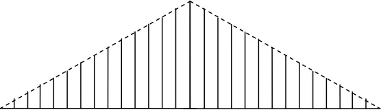
k represents one cycle where k is the number of bits used in constructing the accumulator circuit. As a consequence, the output ofthe phase accumulator is linearly increasing phase value of the synthesized signal as shown in Figure 3, generated in the form of a k - bit digital number with the magnitude of the phase
increment determined by the frequency of the synthesized signal as phase increment =
2
f
d/
f
srad, where
f
d is the desired frequency output, andf
sis the reference clock.Figure-3. N phase input to the quadrant complementer program.
The phase increment, therefore, is small for low synthesized frequency and large for high ones. After N phase samples produced from the phase accumulator, it will recycle causing the accumulator to read the contents of the ROM from button to top to produce the second quadrant's
phase samples as shown in Figure 4. After another N phase, the microprocessor will recycle again but in a negative sign to produce the negative part of the signal. The ROM is a sine function table
of
2
kword, M bit per word capacity that converts the phase information provides by the phase accumulator into digital amplitude samples of the synthesized wave form. All of bit for each phase sample should appear at the input of the DAC at exactly the same time. Otherwise, the differentoperation times of the DAC bit switches will produce a disorganized from one sample to the next, affecting the spectral purity of the synthesized signal. In this manner the DAC is updated at a rate
equal to
1
/
f
s.771
The LPF attenuates all out of band spurious signals generated in the process of frequency synthesis
by required amount, the output of the low - pass filter assumed to be ideal sinusoid.
Frequency Range and Resolution
The smallest frequency increment synthesized by using such a technique is determined by the
number of phase accumulator bit, k, and is equal to:
min
1
1
4
4
4 2
s
k
f
f
N
NT
T
which is also the lowest synthesized frequency, and hence, the desired frequency is derived from
the last equation as:
min
4
s dLf
f
kf
N
Assuming the cutoff frequency of the ideal low-pass filter is
f
s/
2
then the conditions2
/
s d
f
f
and hence,L
N
/
2
must be satisfied, hence, for minimum resolutionL
1
and:min 2
2
s
d k
f
f
f
and for maximum resolution
L
N
/
2
2
k1 and:max 2
8
2
s s d kLf
f
f
f
It can be seen from the above equations that the number of bits k and the ROM size control the frequency range and resolution of the synthesizer. The range of the generated frequencies can be
increased by either increasing the clock frequency or decreasing the number bits used in the phase accumulator circuits. However, the frequency resolution can be decreased by increasing the numbers of samples stored in the ROM block.
SYSTEM ANALYSIS
The microprocessor can act as an accumulator by increasing the address number by a constant L. This increase gives changes on the X -axis.
First quarter of the signal: The program increases the address number from (00000000)2 to
772
working while it is zero. When the address number exceeds (255)10 a carry will be in the carry
register, then it will stop the procedure of quarter one.
Second quarter of the signal : When the carry is one, a subroutine is called to begin subtracting L from the address number in a reverse motion of quarter one until it reaches zero again. Through this operation, the subroutine makes the samples of the second quarter.
Third quarter: When the number of the address reaches zero again, another subroutine is called to increase the address number again and subtracting the value stored in the memory under this
location from zero. This execution continues until it reaches 255.
Fourth quarter: After that, a third subroutine makes a decrement in the address number again until it reaches zero with subtracting the value in the memory under this number of address from zero and this will give the fourth and complete signal with the desired frequency.
CONCLUSION
In this paper, a type of frequency synthesizers is introduced. It depends on the single quadrant idea
using a microprocessor.
Single quadrant is preferred in this technique because it uses only 25% of the ROM, which gives a
4 times better resolution in the synthesis process. This system may be easily built using simple elements
ACKNOWLEDGEMENT
The author would like to thank Palestine Technical University - Kadoorie for sponsoring this work.
REFERENCES
Egan, W.F., Frequency synthesis by phase lock. Wiley interscience.
Gorski, J., Frequency synthesis: Techniques and applications. IEEE Press.
Mamassewitsch, V., Frequency synthesizers, theory and design. Second Eds Edn.: Wiley
interscience.
Saul, P., Direct frequency synthesis- a review of the techniques and potentials. Plessey Research Caswell.