IJEDR1603152
International Journal of Engineering Development and Research (www.ijedr.org)945
Study of Surface and Sub Surface Highway Drainage
System
Tejas D. Khediya
Lecturer in Civil Engineering Department Sir Bhavsinhji Polytechnic Institute-Bhavnagar-Gujarat
________________________________________________________________________________________________________
Abstract - One of the major reasons of deterioration of roads is rain water. During Rainfall, Part of water flows on ground
surface and part of it percolates through soil mass until it reaches the ground water below water table. Due to percolation of water in highway pavement moisture content of soil increases which reduce the bearing capacity of the soil. Thus stability of highway is reduced. Drainage of the highway is the process of removing and controlling surplus water on the surface and sub soil water in sub surface with in the right way which is detailed explain in this paper.
Key words - Drainage, surface water, sub surface water
________________________________________________________________________________________________________
1. Introduction:
Highway drainage is an essential part of highway design and construction which remove the surplus water with in the highway limits and satisfactory dispose it.Road way drainage is mainly due to surface runoff from adjacent area, precipitation of rain and moisture rising by capillarity from the ground water table. Removal and diversion of surface water from road way and adjoining land is known as surface drainage. Removal of excess sub soil water from the subgrade is termed as sub surface drainage.
2. Importance of highway drainage:
The importance of drainage is one of the most important aspects for location and design of highway because of following reasons:
To prevent subgrade failure: Soil subgrade excess moisture reducing the stability of pavement which leads to subgrade failure.
To prevent reduction in strength of pavement material: The strength of pavement material like stabilized soil and WBM (water bound macadam) is reduced.
To prevent frost action: In flexible pavement the formation of waves and corrugation take place due to poor drainage. Decrease volume changes: Volume of subgrade is change especially in clayey soils due to variation in moisture content.
This sometimes leads to pavement failure.
Prevent mud pumping failure: Mud pumping is due to presence of water in subgrade soil especially in rigid pavement. To prevent shoulders and pavement edge: Excess water on shoulders and pavement edge cause considerable damage. Prevent slope failure: Excess moisture causes increase in weight and thus increases in stress and simultaneously
reduction in strength of soil mass which result into failure of earth slopes and embankment foundations. Prevent erosion of soil: Due to surface water, erosion of soil from top of road and slope of embankment. Thus drainage is the important factors governing the highway design and construction.
3. Surface drainage:
Under the surface drainage, water is to be collected in longitudinal drains and then disposed of at the nearest stream, valley or water course. Surface water is removed from surface of road by providing camber or cross slope to the road surface. The road surface is also made impervious to prevent the water entering the subgrade. The recommended ranges of camber for different types of pavement are as per Table-1.
Table-1
Recommended values of camber for different types of road surface Sr.
No. Pavement surface Recommended range
1 Earthen road 1 in 20 to 1 in 25
2 Gravel road 1 in 25 to 1 in 30
3 Water bound macadam 1 in 35 to 1 in 48
4 Bituminous road 1 in 48 to 1 in 60
5 Cement concrete road 1 in 60 to 1 in 72
In surface drainage we have to take into account the period of frequency of flood, various drainage structure like culverts and gutters, road side channels, cross slope and side slope, catch drains, longitudinal gradients etc.
IJEDR1603152
International Journal of Engineering Development and Research (www.ijedr.org)946
should not be less than 2 meters.Surface drainage system arrangement in embankment is shown in Fig-1. On low embankments about 1.8 to 2.0 m high, side slope is 1:4 and protected by vegetation. The velocity of flow can be reduced by giving flat slope to the shoulders.
Fig-1 Surface drainage in Road embankment 3.2 Road in cutting
When the road is in cutting the drains are provided on either side of formation in Fig-2.In these case the drains just after the edge of formation. In places where there is a restriction of spacing. Construction of deep open drains may be undesirable. Road formation in cutting covered drains filled with layers of coarse sand and gravel may be used. See Fig-3.
Fig-2 Surface drainage in cutting
Fig-3 Covered drainage trenches 3.3 Road on ground line
IJEDR1603152
International Journal of Engineering Development and Research (www.ijedr.org)947
Fig-4 Road in ground line3.4 Surface drainage system in urban roads
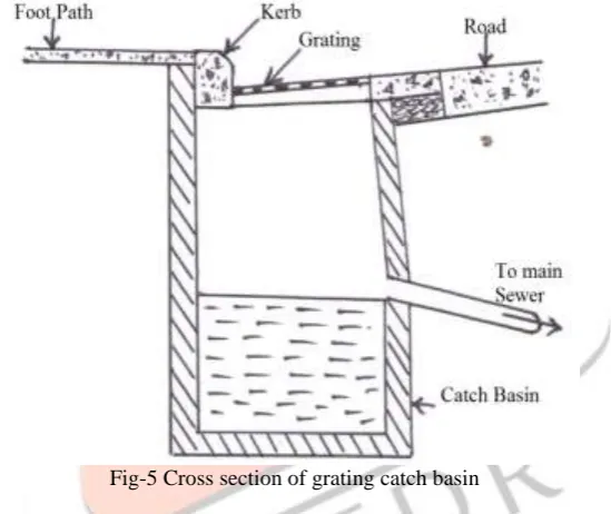
Because of limitation of land and due to the presence of foot path, dividing island, it is necessary to provide underground longitudinal drainage. Water drained from pavement surface can be carried forward in longitudinal direction. This water may be collected in catch basin at suitable interval and lead through underground drainage pipes. Section of catch pit with grating to prevent the entry of rubbish into the drainage system is shown in Fig-5.
Fig-5 Cross section of grating catch basin 3.5 Cross drainage
Whenever highway crosses a river or stream, cross drainage works have to be provided. Sometimes water from side drains also is diverted away from the road through cross drains to divert water from the road to a water course. On highways usually culverts and bridges are used as cross water way of about 6 m, and then the cross drainage structure is known as culvert. For higher discharge and greater linear way the structure is known as bridge.
4. Sub surface water drainage
The change in moisture content of soil affects its bearing capacity of soil. The increase in moisture content of soil reduces its bearing capacity. Thus keeping this point in view, there should not occur any change in moisture content of the subgrade of the road. The change in moisture content of the subgrade is due to fluctuations in the ground water table, seepage flow, percolation of rain water and capillary water. Thus the aim of the sub soil drainage is to prevent changes in the moisture content of the subgrade.
4.1 Control of sub soil flow
IJEDR1603152
International Journal of Engineering Development and Research (www.ijedr.org)948
Fig-6 Intercepting DrainsIn case, the seepage zone is wide and impermeable strata are deep, the drain to keep the water table about 1.3 m below the formation has been found satisfactory. In such situation it is economical to take the trench to the impervious strata and intercept the seepage. (See Fig-7).
Fig-7 Deep drain 4.2 Control of high water table
In order to avoid excessive pressure on subgrade and pavement it is essential that water table should be fairly below level of subgrade. It has been found that water table should be kept at least 1.2 m below the subgrade.
In place where the formation level is to be kept at or below the ground level, it necessary to lower the water table. It is possible to lower the water table in relatively permeable soil by construction of longitudinal drainage trenches with drain pipe and filter sand (See Fig-8)
Fig-8 Lowering high water table in permeable soils
IJEDR1603152
International Journal of Engineering Development and Research (www.ijedr.org)949
Fig-9 Sub surface drainage system with Transverse drains4.3 Control of capillary rise
In place where capillary rise detrimental to the subgrade than controlling capillary rise is more effective than lowering the water table by providing a layer of granular material of suitable thickness between the subgrade and highest level of surface water table during construction period of the embankment. The thickness of granular material should be such that the capillary water cannot rise above the granular material as shown in Fig-9.In place of granular layer, impermeable or bituminous layer may be provided.
Fig-10 Control of capillary rise by granular layer
5. Conclusion
Based on above study we can say that Highway drainage is process of removing and controlling excess surface and sub soil water with in the right way. Highway drainage is an important part for design and construction of highway. In surface drainage, surface water is intercepted and diverted to a natural stream. If it is not done the surface water causing erosion. In sub surface water drainage, sub surface water is intercepted and disposed of to safe place.
6. References:
[1]A course in Highway Engineering “S.P.Bindra”.
[2]Roads, Railways, Bridges, Tunnels & Harbour Dock Engineering, “B.L.Gupta & Amit Gupta”Edition-2012 [3]Highway Engineering, “S.K.Khanna & C.E.G. Justo”, Edition-200