CSEIT1846119 | Published – 08 May 2018 | May-June 2018 [ (4 ) 6 : 634-639 ]
National conference on Engineering Innovations and Solutions (NCEIS – 2018)
International Journal of Scientific Research in Computer Science, Engineering and Information Technology
© 2018 IJSRCSEIT | Volume 4 | Issue 6 | ISSN : 2456-3307
634
Automation of Compression Testing Machine
Julia George, Rakesh M
Department of Mechanical Engineering, the National Institute of Engineering, Mysuru, Karnataka, India
ABSTRACT
The main prospective of this paper is to analyze the working and testing procedure for the automation of Compression Testing Machine (CTM). Load cells of higher weights are being manufactured which needs to be calibrated and tested for their quality. Here Mitsubishi PLC are used to automate the setup. The reason for automating the setup is to reduce the human interference and to get the expected results. The data which observed during calibration and testing of the machine is then stored in the database.
Keywords: Compression Testing Machine, Load cell, PLC, Database.
I. OBJECTIVES.
To automate the testing procedure by using PLC. To decrease the work time using control system. To store the value of the reading in HMI so we
can take down the readings at any time
II. INTRODUCTION which it is termed as “universal”. The main purpose of this machine is to test any load bearing devices like weighing systems. One of the testing machine is compression testing machine (CTM).
III. PROBLEM STATEMENT
The testing in CTM is being done manually where 2 persons are required one who will increase the pressure being applied on the test load cell and the other person to note down the reading for the
corresponding weight. This requires patience as the reading has to be noted immediately as it can’t be stored in the device while testing manually.
IV. COMPRESSION TESTING MACHINE
A Compression Testing Machine (CTM) is used to determine the compressive strength of materials [1]. The reason for performing compression test is to determine the specimen behavior under compressed load conditions, to check the quality of the material, to aid in design process, etc.
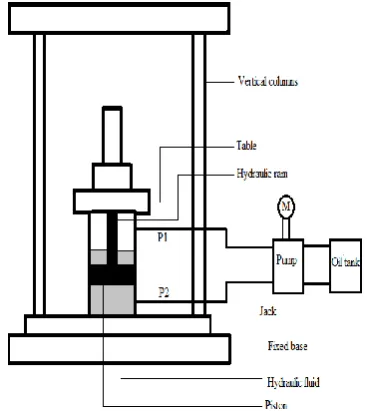
pumping system consists of a pump cylinder, a handle socket and a pumping bar.
The working of the jack is as follows when the pumping system is activated by inserting the pumping bar into the handle socket and pumping it, the hydraulic fluid is pushed to the cylinder though port P2, applying pressure to the fluid while filling the cylinder. This exerts pressure on the piston and the hydraulic ram moves upward. When the required pressure is applied on the test load cell, the corresponding readings of the reference load cell and the test load cell is noted down. When the hydraulic fluid is pumped into the cylinder through port P1 then the pressure exerted on the piston will lower the ram. If the difference between the values exceeds a particular limit then the test load cell is defective and it is rejected
Figure 1. Schematic diagram of CTM
V. CONTROL SYSTEM
In the conventional CTM the whole procedure is done manually and the testing procedure will take almost 30 minutes and above based on the capacity of the load cell. The below tabular column shows the readings of weight against millivolt reading of 20 ton loadcell by manual testing which took about 30 minutes.
Table 1. Weight against mV reading of manual testing of 20tonne compression load cell.
Load(Ton) mV principle diagram of CTM. The force applied on the test and reference load cells are converted into hydraulic fluid the servo valve functions and thereby it operates the hydraulic jack.
the test load cell are then displayed to the control panel with a HMI which communicates with the PLC using RS-485 communication.
Figure 2. Control principle diagram of CTM.
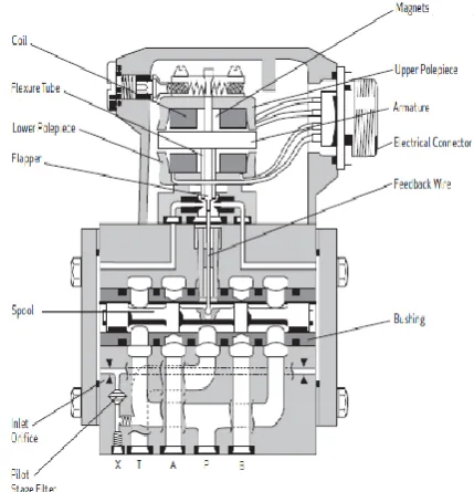
Figure 3. Schematic diagram of the control system of CTM operating pressure at the ports P, A, B, T is 315 bars. The working description of the servo valve is as follows. The servo valve consists of an electrical torque motor and a two stage of hydraulic power amplification. The motor armature extends into the air gap of the magnetic flux circuit and is supported in this position by a flexure tube member. The tube member acts as a seal between the electromagnetic and hydraulic sections of the valve. The 2 motor coils surround the armature, one on each side of the flexure tube. The pilot stage in the servo valve uses a flapper nozzle mechanism. The flapper of the first stage hydraulic amplifier is rigidly attached to the
armature. The flapper extends through the flexure tube and passes between the two nozzles, creating two variable orifices between the nozzle tips and the flapper. The pressure controlled by the flapper and the nozzle variable orifice is then fed to the end areas of the second stage of spool.
The second stage is a conventional four way spool design in which the output flow from the valve at a fixed valve pressure drop is proportional to spool displacement from the null displacement. A cantilever feedback spring is fixed to the flapper and engages a slot at the center of the spool. Displacement of the spool deflects the feedback spring which creates a force on the armature or flapper assembly. The spool movement continues till the feedback wire force is equal to the input signal forces.
Figure 4. Schematic diagram of Moog G631 series servo valve
B. Servo valve controller
value is routed via an adjustable ramp with a quadrant detector. This ramp can be deactivated. The I component of the controller can also be deactivated, permitting operation as a P or a PD controller. The target value can be adjusted via a spindle resistor relative to the actual value. Since the valve coil is operated on one side toward 0V, the control module’s end stage can also be used as a current driver or U/I converter.
C. Programmable Logic Controller
Mitsubishi’s Nexgenie 1000 PLC and its analog output expansion module NE02AX is used. The expansion module provides 2 non-isolated channels and 16 bit resolution ADC cum DAC which converts the 16 bit digital value into 4 types of analog outputs (0 to 10VDC,-10 to +10VDC, and 0/4 to 20mA). The expansion module has an on board processor and memory. Up to four expansion units can be interfaced to the base unit. Expansion unit has interface cable strip with polarized plug on the left side. This cable can be connected to the base unit or any expansion unit. The ladder programming for this PLC is done in Co-Desys software.
VII. SOFTWARE .
The ladder logic of Mitsubishi PLC is done is Co-Desys software with an interfacing to HMI [4].The software programming of the machine consist of 4 modes namely, Manual, Multistep, Trimming and Cycling. Manual mode is where the operator enters the required set point and waits for the machine to respond. Multistep mode allows the calibration of the load in n number of steps specified by the operator. The data after the completion of the all the steps gets stored in the HMI Trimming mode is similar to manual mode the only difference is that if the output of the test load cell is not right then the side of the load cell are trimmed to get the accurate output. Cycling mode is that the operator enters the number of cycles to be performed. and their values are taken down for each cycle and care must be taken that only +0.001 to -0.001 tolerance in the
milli volt reading from both the cycles are maintained. If both values are absurd then the load cel is a rejected piece. The HMI screens of the program are shown in figure 1.5 below.
(a)
(c)
(d)
(e)
(f)
(h)
Figure 1.5 (a) HMI screen of the modes of operation.(b) HMI screen of Multi Step mode.(c) HMI screen of Cycling mode.(d) HMI screen of Trimming and Manual mode.(e) HMI screen of the values stored during multistep mode.(f) HMI screen of Tare and Calculation.(h) HMI screen of tolerance value of the reading.
VIII. EXPECTED RESULT AND CONCLUSION.
XI ACKNOLEDGMENT
We take this opportunity to give faithful gratitude to IPA Private Limited. for giving an excellent opportunity to carry out the project.
X. REFERENCES.
[1] Fei Hu , Wenqing Yin , Cairong Chen “ Design of the tensile testing machine computer control system based on MCGS” 2010 International Conference on Challenges in Environmental Science and Computer Engineering.
[2] WANG Jian-xin, “Development of universal testing machine remote test and detection system,” Journal of Transducer Technology, vol. 23, May. 2014, pp. 29-31.
[3] “Universal Testing Machine Motion Control System” by Sagar S Patel, Gayathri K M 2013.