National conference on Engineering Innovations and Solutions (NCEIS – 2018)
International Journal of Scientific Research in Computer Science, Engineering and Information Technology
© 2018 IJSRCSEIT | Volume 4 | Issue 6 | ISSN : 2456-3307
A Solar Input Wpt Using Resonance Induction Coupling
Shilpshri V N, Vidyashree M S
Asst.Professor, Department of EEE, GSSSIETW, Mysuru, Karnataka, India
ABSTRACT
Solar Power Satellites (SPS) converts solar energy into electromagnetic waves and sends that microwaves in to a beam to a receiving antenna on the Earth for conversion to ordinary Electricity. SPS is a clean, large-scale, stable electric power source. For SPS Wireless power transmission is essential. WPT contains microwave beam, which can be directed to any desired location on Earth surface. This beam collects Solar Energy and converts it into Electrical Energy. This concept is more advantageous than conventional methods. The SPS will be a central attraction of space and energy technology in coming decades. It is not a pollutant but more aptly, a man made extension of the naturally generated electromagnetic spectrum that provides heat and light for our sustenance. Wireless Power transmission (WPT) is a useful and convenient technology that can be employed to collect solar energy and concentrate on earth surface without the need for a wire connection called solar power satellites (SPS). This project provides an analysis of wireless power transfer with an assessment of its practical applicability in terms of power range and efficiency. Wireless power transmission is a useful and convenient technology that can be employed to collect solar energy (Renewable energy) and concentrate on earth surface without the need for a wire connection. Transferring of electrical energy from transmitting to receiving antenna up to 20 V of input 12 V of frequency 65 KHz transfer up to the distance of 10 cm
Keywords. Solar Panel, Capacitor Bank, High Frequency Converter, Half bridge Driver, Resonant Transmitter Antenna, HF Rectifier Resonant Receiver Antenna.
I.
INTRODUCTION
Recently, wireless power supply devices which supply electric power wirelessly (in the medium of air) to apparatuses without power cables or the like have come to be in practical use. The principles upon which wireless electric power transmission is realized are generally categorized into three types.
Electromagnetic induction type, Radio reception type and Resonance type.
Electromagnetic induction non-contact power transmission employs the phenomenon in which application of an electric current to one of adjacent
coils induces an electromotive force in the other coil with magnetic flux as the medium.
Wireless power transfer (WPT) is a breakthrough technology that provides energy to communication devices without the power units. With the remarkable progress being made recently, this technology has been attracting a lot of attention of scientists and R&D firms around the world. Recently, the usage of mobile appliances such as cell phones, PDAs, laptops, tablets, and other handheld gadgets, equipped with rechargeable batteries has been widely spreading.
Theoretically, we can use all electromagnetic waves for a wireless power transmission (WPT). The difference between the WPT and communication systems is only efficiency. Maxwell’s Equations indicate that the electromagnetic field and its power diffuse to all directions. Though we transmit energy in a communication system, the transmitted energy is diffused to all directions. Though the received power is enough for a transmission of information, the efficiency from the transmitter to receiver is quiet low. Therefore, we do not call it the WPT system.
A system of Wireless Power Transfer (WPT) transmits power to the device which has to work without any wires, and is the key subsystem of the
Future Fast, Flexible, Free-Flying, and Fractionated (F6) System. The WPT technology is very important for the space solar power station and deep-space exploration, and it could break the limit of capability and operation for satellites and make the satellites much lighter, smaller and more flexible and durable. Moreover the WPT system could transmit power to a space vehicle in order to supply the power for interstellar probe. Currently, the WPT system utilizes the microwave and laser as the medium of transmitting power.
II.
BLOCK DIAGRAM & CIRCUIT DIAGRAM
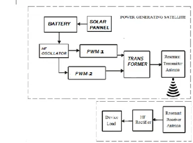
A. BLOCK DIAGRAM
B. CIRCUIT DIAGRAM
1. Transmitter Unit
Figure 2. Transmitter side circuit
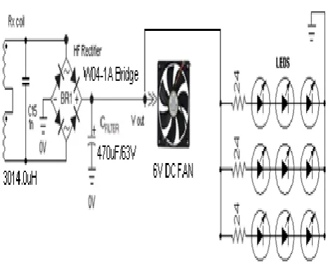
Receiver Unit
Figure 3. receiving side circuit.
III.
DESCRIPTION
a. Solar Panel PVArray
Solar PV arrays collect light radiation from the space and convert them into DC electrical output. b. Super Capacitor Bank
Super capacitor bank stores the electrical output from the solar panels and provides to the power converter.
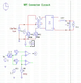
c. High Frequency Converter
High frequency converter consists of a high frequency oscillator which generates PWM pulses and drives the Mosfets. Here two separate PWM pulses PWM1 and PWM2 are produced and supplied to the Mosfet gate.
d. Resonant Transmitter Antenna
The transmitter antenna is designed with windings of copper coils which convert the high frequency oscillating electrical current into Electromagnetic waves resonating ant a particular frequency.
e. Resonant Receiver Antenna
f. HF Rectifier
HF rectifier consists of fast switching rectifier diodes which converts HF voltage into DC voltage and filters the output voltage which is utilized by the loads.
IV.
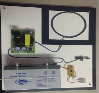
HARDWARE DETAILS
Wireless power transmission is not a new idea. Nikola Tesla demonstrated transmission of electrical energy without wires in early 19th century. Tesla used electromagnetic induction systems. William C Brown demonstrated a micro wave powered model helicopter in 1964. This receives all the power needed for flight from a micro wave beam. In 1975 Bill Brown transmitted 30kW power over a distance of 1 mile at 84% efficiency without using cables. Researchers developed several technique for moving electricity over long distance without wires. Some exist only as theories or prototypes, but others are already in use.
Consider an example, in this electric devices recharging without any plug-in. The device which can be recharged is placed on a charger. Supply is given to the charger and there is no electrical contact between charger and device.Previous schemes for wireless power transmission included attempts by the late scientist Nikola Tesla and the Microwave power transmission. Both Tesla's design and the later microwave power were forms of radiative power transfer. Radiative transfer, used in wireless communication, is not particularly suitable for power transmission due to its low efficiency and radiative loss due to its Omni directional nature.
Table 1
Solar output voltage 12 V
Transformer output voltage 20 V
Frequency across
Transmission and receiver side
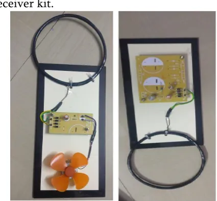
Receiver kit.
Figure 5. receiving side hardware kit
V.
METHODS OF WIRELESS POWER
TRANSMISSION
There are 3 types of wireless power transmission Inductive coupling.
Transformer coupling.
Resonant Inductive Coupling.
Radio and Microwave Energy Transfer.
a) Inductive Coupling
The coupling between two electric circuits through inductances linked by a common changing magnetic field.
b) Transformer Coupling
Electrical energy transferred from one circuit to another with by use of a magnetic core.
c) Radio & Microwave Energy Transfer
To use RF or Microwave energy for transmitting power, in which the radiated RF energy from an antenna is extracted and converted into usable energy through a receiving antenna.
d) Resonant Inductive Coupling
The inductive coupling is the resonant coupling between the coils of two LC circuits with the same resonant frequency, transferring energy from one coil to the others.
Figure 6. Resonant Inductive Coupling
With inductive resonance, electromagnetic energy is only transferred to recipient devices that share the identical resonant frequencies as the energy source, so energy transfer efficiency is maintained, even when misalignment occurs.
VI.
VOLTAGE RECTIFIER
A rectifier would be needed to rectify the AC voltage received from the receiver coil to drive a DC load. A type of circuit that produces an output waveform that generates an output voltage which is purely DC or has some specified DC component is a Full Wave Bridge Rectifier. This type of single phase rectifier uses four individual rectifying diodes connected in a closed loop "bridge" configuration to produce the desired output. The smoothing capacitor connected to the bridge circuit converts the full-wave rippled output of the rectifier into a smooth DC output voltage.
Since the diodes had to rectify AC signals of Megahertz frequencies, fast signal diodes, MIC6A4, had to be used for the bridge circuit. However we did not implement this circuit with our final setup as we did not drive a DC load with our setup.
VII.
OSCILLATOR
There are two general classes of oscillators. sinusoidal and relaxation. Op-Amp sinusoidal oscillators operate with some combination of positive and negative feedback to drive the op-amp into an unstable state, causing the output to transition back and forth at a continuous rate. Relaxation Op-Amp oscillators operate with a capacitor, a resistor or a current source to charge/discharge the capacitor, and a threshold device to induce oscillation.
VIII.
SWITCHING MOSFET’S
The main idea behind the switch-mode Power Amplifier technology is to operate a MOSFET in saturation so that either voltage or current is switched on and off. The figure below shows the circuit diagram of the switch-mode power amplifier.
Figure 8. Switching MOSFET’S
Our switch-mode design consisted of a MOSFET IRF 510, which when turned on allowed large current from the DC power supply to flow through the resistor of 50 Ohms and through the transmitting antenna to transfer current from the power supply through the transmitting coil. The current and voltage required to drive the gate of the MOSFET
IRF 510 was supplied by the MOSFET IRF 640 whose gate was driven by the input signal from a Hewlett Packard signal generator. The maximum voltage when the coils were tuned at resonance was recorded to be around 102.3V.
WIRELESS POWER CALCULATIONS
i. FREQUENCY CALCULATION
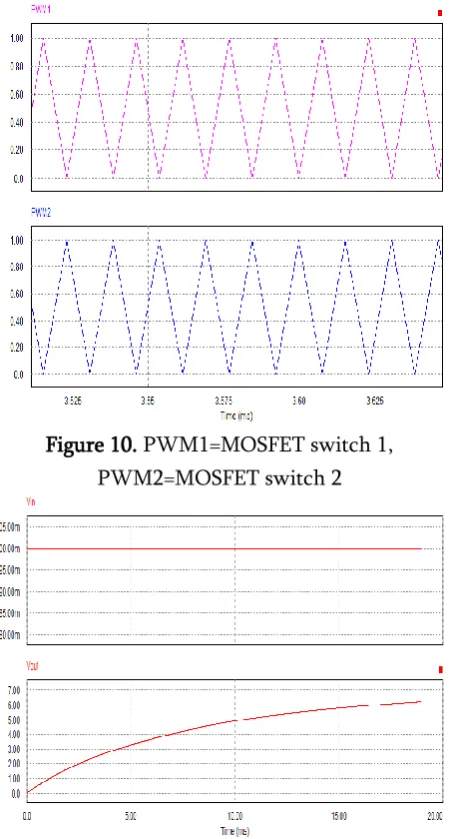
ii. SIMULATION OUTPUT CIRCUIT AND WAVE
FORM
Figure 10. PWM1=MOSFET switch 1, PWM2=MOSFET switch 2
Figure 11. input and output voltage wave form
IX.
APPLICATIONS OF THE PROJECT
Wireless power has a bright future in providing wireless electricity. There are no limitations in power applications. Some of the potential applications are powering of cell phones, laptops and other devices that normally run with the help of batteries or plugging in wires. Wireless power applications are expected to work on the gadgets that are in close proximity to a source of wireless 'power, where in the gadgets charges automatically without necessarily, having to get plugged in. By the use of Wireless power there is no need of batteries or remembering to recharge batteries periodically. If a source is placed in each room to provide power supply to the whole houseWireless power has many
medical applications. It is used for providing electric power in many commercially available medical implantable devices.Another application of this technology includes transmission of information. It would not interfere with radio waves and it is cheap and efficient.
X.
BENEFITS
No need of line of sight - In Wireless powertransmission there is any need of line of sight between transmitter and receiver. That is power transmission can be possible if there is any obstructions like wood,metal, or other devices were placed in between the transmitter andreceiver.No need of power cables and batteries - Wireless power replaces the use of power cables and batteries.Does not interfere with radio wavesNegative health implications - By the use of resonant coupling wavelengths produced are far lower and thus make it harmless.Highly efficient than electromagnetic induction - Electromagnetic induction system can be used for wireless energy transfer only if the primary and secondary are in very close proximity. Resonant induction system is one million times as efficient as electromagnetic induction system.Less cost - The components of transmitter and receivers are cheaper. So this system is less costly.
XI.
CONCLUSION
solutions to overcome these barriers. In the last decade, photovoltaic technologies have experienced an astonishing evolution that led to the increase of the efficiency of crystal-silicon solar cells up to 95%.
XII.
REFERENCES
1. T. Blackwell, “Recent demonstrations of laser power beaming at DFRC and MSFC,” AIP Conference Proceeding, Beamed Energy Propulsion. Third International Symposium on Beam Energy Propulsion, vol. 766, pp.73-85, Apr. 2005.
2. G. Chattopadhyay, H. Manohara, M. Mojarradi, Tuan Vo, H. Mojarradi, Sam Bae, and N. Marzwell, “Millimeter-wave wireless power transfer technology for space applications,” Asia-Pacific Microwave Conference, pp.1-4, Dec. 2008.
3. H. H. Wu, G. A. Covic, J. T. Boys, and D. J. Robertson, “A series-tuned inductive-power-transfer pickup with a controllable AC-voltage output,” IEEE Transactions on Power Electronics, vol.26, no.1, pp.98-109, Jan. 2011. 4. S. P. Kamat, “Energy management architecture
for multimedia applications in battery powered devices,” IEEE Transactions on Consumer Electronics, vol.55, no.2, pp.763-767, May 2009. 5. M. Kato and C. -T. D. Lo, “Power Consumption
Reduction in Java-enabled, Battery-powered
Handheld Devices through Memory
Compression,” IEEE International Symposium on Consumer Electronics, pp.1-6, 20-23 June 2007. 6. A. Karalis, J. D. Joannopoulos, and M. Soljacic,