Debugging Package for
Motorola 68K CISC CPUs
User's Manual
(Part 1 of 2)
Notice
While reasonable efforts have been made to assure the accuracy of this document, Motorola, Inc. assumes no liability resulting from any omissions in this document, or from the use of the information obtained therein. Motorola reserves the right to revise this document and to make changes from time to time in the content hereof without obligation of Motorola to notify any person of such revision or changes.
No part of this material may be reproduced or copied in any tangible medium, or stored in a retrieval system, or transmitted in any form, or by any means, radio, electronic, mechanical, photocopying, recording or facsimile, or otherwise, without the prior written permission of Motorola, Inc.
It is possible that this publication may contain reference to, or information about Motorola products (machines and programs), programming, or services that are not announced in your country. Such references or information must not be construed to mean that Motorola intends to announce such Motorola products, programming, or services in your country.
Restricted Rights Legend
If the documentation contained herein is supplied, directly or indirectly, to the U.S. Government, the following notice shall apply unless otherwise agreed to in writing by Motorola, Inc.
Use, duplication, or disclosure by the Government is subject to restrictions as set forth in subparagraph (c)(1)(ii) of the Rights in Technical Data and Computer Software clause at DFARS 252.227-7013.
Motorola, Inc. Computer Group 2900 South Diablo Way
Preface
The Debugging Package for Motorola 68K CISC CPUs User's Manual provides general information for the onboard Þrmware package for all Motorola 68000 CISC CPU and MPU VMEmodule boards.
This document is bound in two parts. Part 1 (68KBUG1/D3, this volume) contains the Table of Contents and Chapters 1 through 3. Part 2 (68KBUG2/D3) contains Chapters 4 and 5, Appendices A through I, and the Index.
This manual is intended for anyone who wants to design OEM systems, supply additional capability to an existing compatible system, or work in a lab
environment for experimental purposes.
The following Þrmware packages and boards are covered in this manual:
The Þrmware packages are referred to as 16XBug in this manual. The boards are referred to as MVME16X.
This manual describes the debugger, the debugger command set, the one-line assembler/disassembler, and system calls. These functional elements are common to all Þrmware packages.
Installation, start-up, diagnostics tests, and environmental parameters are described in the diagnostic manuals for each of the Þrmware packages.
A basic knowledge of computers and digital logic is assumed.
Motorola and the Motorola symbol are registered trademarks of Motorola, Inc.
SYSTEM V/68 is a trademark of Motorola, Inc.
Timekeeper and Zeropower are trademarks of SGS-THOMSON Microelectronics.
MVME162 162Bug
MVME172 172Bug
MVME166 166Bug
MVME167 167Bug
MVME176 176Bug
Related Documentation
The following publications are applicable to Motorola 68K CISC CPU debugging packages and may provide additional helpful information. If not shipped with this product, they may be purchased by contacting your local Motorola sales ofÞce. Non-Motorola documents may be obtained from the sources listed following the table.
Document Title Motorola
Publication Number
M68040 Microprocessors User's Manual M68040UM/AD M68060 Microprocessors User's Manual M68060UM/AD MVME050 System Controller Module User's Manual MVME050/D MVME162 ProgrammerÕs Reference Guide MVME162PG/D MVME162FX ProgrammerÕs Reference Guide MVME162LXPG/D MVME162LX ProgrammerÕs Reference Guide V162FXA/PG MVME172 ProgrammerÕs Reference Guide VME172A/PG Single Board Computers Programmer's Reference Guide VMESBCA1/PG and
VMESBCA2/PG 162BugDiagnostics UserÕs Manual V162DIAA/UM 167Bug Debugging Package UserÕs Manual MVME167BUG/D 172Bug Diagnostics UserÕs Manual V172DIAA/UM 177Bug Diagnostics User's Manual V177DIAA/UM MVME320B VMEbus Disk Controller Module User's Manual MVME320B/D MVME323 ESDI Disk Controller User's Manual MVME323/D MVME327A VMEbus to SCSI Bus Adapter and
MVME717 Transition Module User's Manual
Note Although not shown in the above list, each Motorola Computer Group manual publication number is suffixed with the revision level of the document, such as Ò2Ó (the second revision of a manual); a supplement bears the same number as a manual but has a suffix such as "2A1" (the first supplement to the second revision of the manual).
The following publications are available from the sources indicated.
ANSI Small Computer System Interface-2 (SCSI-2), Draft Document X3.131-198X, Revision 10c; Global Engineering Documents, P.O. Box 19539, Irvine, CA 92714.
Versatile Backplane Bus: VMEbus, ANSI/IEEE Std. 1014-1987, The Institute of Electrical and Electronics Engineers, Inc., 345 East 47th Street, New York, NY 10017 (VMEbus SpeciÞcation). This is also available as Microprocessor system bus for 1 to 4 byte data, IEC 821 BUS, Bureau Central de la Commission Electrotechnique Internationale; 3, rue de VarembŽ, Geneva, Switzerland.
Manual Terminology
Throughout this manual, a convention has been maintained whereby data and address parameters are preceded by a character which speciÞes the numeric format as follows:
Unless otherwise speciÞed, all address references are in hexadecimal throughout this manual.
An asterisk (*) following the signal name for signals which are level signiÞcant denotes that the signal is true or valid when the signal is low.
An asterisk (*) following the signal name for signals which are edge signiÞcant denotes that the actions initiated by that signal occur on high to low transition.
$ hexadecimal character
% binary number
In this manual, assertion and negation are used to specify forcing a signal to a particular state. In particular, assertion and assert refer to a signal that is active or true; negation and negate indicate a signal that is inactive or false. These terms are used independently of the voltage level (high or low) that they represent.
Data and address sizes are deÞned as follows:
❏ A byte is eight bits, numbered 0 through 7, with bit 0 being the
least significant.
❏ A word is 16 bits, numbered 0 through 15, with bit 0 being the
least significant.
❏ A longword is 32 bits, numbered 0 through 31, with bit 0 being
the least significant.
Conventions
The following conventions are used in this document:
bold is used for user input that you type just as it appears. Bold is also used for commands, options and arguments to commands, and names of programs, directories, and files.
italic is used for names of variables to which you assign values. Italic is also used for comments in screen displays and examples.
courier is used for system output (e.g., screen displays, reports), examples, and system prompts.
<RETURN> or <CR> represents the carriage return or Enter key.
CTRL or ^ represents the Control key. Execute control characters by pressing the
The computer programs stored in the Read Only Memory of this device contain material copyrighted by Motorola Inc., 1995, and may be used only under a license such as those contained in MotorolaÕs software licenses.
The software described herein and the documentation appearing herein are furnished under a license agreement and may be used and/or disclosed only in accordance with the terms of the agreement.
The software and documentation are copyrighted materials. Making unauthorized copies is prohibited by law. No part of the software or documentation may be reproduced, transmitted, transcribed, stored in a retrieval system, or translated into any language or computer language, in any form or by any means without the prior written permission of Motorola, Inc.
Disclaimer of Warranty
Unless otherwise provided by written agreement with Motorola, Inc., the software and the documentation are provided on an Òas isÓ basis and without warranty. This disclaimer of warranty is in lieu of all warranties whether express, implied, or statutory, including implied warranties of merchantability or Þtness for any particular purpose.
!
WARNING This equipment generates, uses, and can radiate
electro-magnetic energy. It may cause or be susceptible to electro-magnetic interference (EMI) if not installed and used in a cabinet with adequate EMI protection.
©Copyright Motorola 1997 All Rights Reserved
List of Figures
List of Tables
Debugger Address Parameter Formats 2-5 Exception Vectors Used by 16XBug 2-11 Debugger Commands 3-1
1
1
General Information
Introduction
16XBug is a powerful evaluation and debugging tool for systems built around the MVME16X CISC-based single-board computer and embedded controller modules. Facilities are available for loading and executing user programs under complete operator control for system evaluation.
16XBug includes commands for display and modification of memory, breakpoint and tracing capabilities, a powerful
assembler/disassembler useful for patching programs, and a self-test at power-up feature which verifies the integrity of the system. Various 16XBug routines that handle I/O, data conversion, and string functions are available to user programs through the TRAP #15 system calls.
Note 167Bug is used in most examples of commands and displays given in this manual. However, the
commands and displays apply to all 68K CISC debugging packages, unless otherwise noted.
Overview of M68000 Firmware
General Information
1
16XBug consists of three parts:
1. A command-driven user-interactive software debugger, described in Chapter 2 and hereafter referred to as "the debugger" or "16XBug".
2. A command-driven diagnostic package for the specific CPU board hardware, described in a separate board-specific debugger manual and hereafter referred to as "the diagnostics".
3. A user interface that accepts commands from the system console terminal.
When using 16XBug, you will operate out of either the debugger directory or the diagnostic directory.
❏ If you are in the debugger directory, the debugger prompt "16X-Bug>" is displayed and you have all of the debugger
commands at your disposal.
❏ If you are in the diagnostic directory, the diagnostic prompt "16X-Diag>" is displayed and you have all of the diagnostic
commands at your disposal as well as all of the debugger commands.
You may switch between directories by using the Switch
Directories (SD) command (refer to Chapter 3), or may examine the commands in the particular directory that you are currently in by using the Help (HE) command (refer to Chapter 3).
Because 16XBug is command-driven, it performs its various operations in response to user commands entered at the keyboard. The flow of control in 16XBug is shown in the individual board-specific debugger manuals. When you enter a command, 16XBug executes the command and the prompt reappears. However, if you enter a command that causes execution of user target code (e.g.,
"GO"), then control may or may not return to 16XBug, depending
16XBug Implementation
1
If you have used one or more of Motorola's other debugging packages, you will find the CISC 16XBug very similar. Some effort has also been made to make the interactive commands more consistent. For example, delimiters between commands and arguments may now be commas or spaces interchangeably.
16XBug Implementation
16XBug is written largely in the "C" programming language, providing benefits of portability and maintainability. Where necessary, assembler has been used in the form of separately compiled modules containing only assembler code - no mixed language modules are used.
16XBug is contained on EPROM, PROM, or FLASH devices, depending on which board is used. These memory devices provide either 512KB or 1MB of storage. The memory provided is larger than the space is occupied by the firmware because of the 32-bit longword-oriented MC68040 and MC68060 memory bus
architecture. The executable code is checksummed at every power-on or reset firmware entry, and the result (which includes a pre-calculated checksum contained in the EPROM, PROM, and FLASH devices), is tested for an expected zero.
Note Do not modify the EPROM, PROM, and FLASH devices unless re-checksum precautions are taken.
General Installation and Start-up
Autoboot
1
being used does not do hardware handshaking via the CTS line, then it must do XON/XOFF handshaking. If you get garbled messages and missing characters, then you should check the terminal to make sure
XON/XOFF handshaking is enabled.
6. If you want to connect devices (such as a host computer system and/or a serial printer) to the other EIA-232-D port(s), connect the appropriate cables and configure the port(s) as detailed in step 5 above. After power-up, this (these) port(s) can be reconfigured by programming the MVME16X serial interface chip, or by using the 16XBug PF command.
Note that some MVME16X modules contain parallel ports. To use a parallel device, such as a printer, with such an
MVME16X module, connect it to the appropriate parallel port per the installation manual for the MVME16X module. However, with any MVME16X, you could add a module such as the MVME335 to the system.
7. Power up the system. 16XBug executes some self-checks and displays the debugger prompt "16X-Bug>" (if 16XBug is in
Board Mode). However, if the ENV command has put 16XBug in System Mode, the system performs a selftest and tries to autoboot. Refer to the ENV and MENU commands in Chapter 3, and to system operation in Appendix A.
If the confidence test fails, the test is aborted when the first fault is encountered. If possible, an appropriate message is displayed, and control then returns to the menu.
Autoboot
ROMboot
1
ROMboot
This function is configured/enabled by the Environment (ENV) command and executed at power-up (optionally also at reset) or by the RB command assuming there is valid code in the EPROM, PROM, or FLASH devices (or optionally elsewhere on the module or VMEbus) to support it. If ROMboot code is installed, a user-written routine is given control (if the routine meets the format requirements). One use of ROMboot might be resetting SYSFAIL* on an unintelligent controller module. The NORB command disables the function.
For a user's ROMboot module to gain control through the ROMboot linkage, four requirements must be met:
1. Power must have just been applied (but the ENV command can change this to also respond to any reset).
2. Your routine must be located within the MVME16X ROM memory map (but the ENV command can change this to any other portion of the onboard memory, or even offboard VMEbus memory).
3. The ASCII string "BOOT" must be located within the specified memory range.
4. Your routine must pass a checksum test, which ensures that this routine was really intended to receive control at power-up.
To prepare a module for ROMboot, the Checksum (CS) command must be used. When the module is ready it can be loaded into RAM, and the checksum generated, installed, and verified with the CS command. (Refer to the CS command description and examples in Chapter 3.)
ROMboot
1
Under control of the ENV command, the sequence of searches is as follows:
1. Search direct address for "BOOT".
2. Search complete ROM map.
3. Search local RAM, at all 8K byte boundaries starting at the beginning of local RAM.
4. Search the VMEbus map (if so selected by the ENV
command) on all 8K byte boundaries starting at the end of the onboard RAM. VMEbus address space is searched both below (if the start address of local RAM is not located at 0) and above local RAM up to the beginning of EPROM, PROM, or FLASH memory space.
The example below performs the following:
1. Outputs a <CR><LF> sequence to the default output port.
2. Displays the date and time from the current cursor position.
3. Outputs two more <CR><LF> sequences to the default output port.
4. Returns control to 167Bug.
Sample ROMboot Routine
Module preparation including calculation of checksum:
The target code is first assembled and linked, leaving $00 in the even and odd locations destined to contain the checksum.
Load the routine into RAM (with S-records via the LO command, or from magnetic media using IOP).
Display the entire module (checksum bytes are at $00010024 and $00010025).
00010000 424F4F54 00000010 00000026 54455354 BOOT...&TEST 00010010 4E4F0026 4E4F0052 4E4F0026 4E4F0026 N0.&NO.RNO.&NO.& 00010020 4E4F0063 00000000 00000000 00000000 NO.c...
167-Bug>md 10010:5;di Disassemble
00010010 4E4F0026 SYSCALL .PCRLF executable
00010014 4E4F0052 SYSCALL .RTC_DSP instructions.
00010018 4E4F0026 SYSCALL .PCRLF
0001001C 4E4F0026 SYSCALL .PCRLF
00010020 4E4F0063 SYSCALL .RETURN
167-Bug>cs 10000:26/2;w Perform checksum on
Effective address: 00010000 locations $10000 through
$10025 (refer to the CS command).
Effective count : &38
Checksum: C226
167-Bug>m 10024;w Insert checksum into bytes $10024, $10025.
00010024 0000? c226.
Again display the entire module (now with checksums).
167-Bug>md 10000 :c;l
00010000 424F4F54 00000010 00000026 54455354 BOOT...&TEST 00010010 4E4F0026 4E4F0052 4E4F0026 4E4F0026 NO.&NO.RNO.&NO.& 00010020 4E4F0063 C2260000 00000000 00000000 NO.c.&...
Verify the functionality of your ROMboot module by executing the RB command. (The "VERBOSE" option reports the progress of the search.)
167-Bug>rb;v
ROMboot in progress... To abort hit <BREAK>
Direct Adr: FFC00000 FFC00000: Searching for ROMboot Module at: FFC00000 ROM : FFC00000 FFC7FFFC: Searching for ROMboot Module at: FFC7E000 Local RAM : 00000000 00FFFFFC: Searching for ROMboot Module at: 00010000 Executing ROMboot Module "TEST" at 00010000
FRI SEP 15 11:50:21.00 1989
Network Boot
1
Network Boot
Network Auto Boot is a software routine contained in the 16XBug EPROM, PROM, or FLASH devices that provides a mechanism for booting an operating system using a network (local Ethernet interface) as the boot device. The Network Auto Boot routine automatically scans for controllers and devices in a specified sequence until a valid bootable device containing a boot media is found or the list is exhausted. If a valid bootable device is found, a boot from that device is started. The controller scanning sequence goes from the lowest controller Logical Unit Number (LUN) detected to the highest LUN detected. (Refer to Appendix G for default LUNs.)
At power-up, Network Boot is enabled, and providing the drive and controller numbers encountered are valid, the following message is displayed upon the system console:
"Network Boot in progress... To abort hit <BREAK>"
Following this message there is a delay to allow you to abort the Auto Boot process if you wish. Then the actual I/O is begun: the program pointed to within the volume ID of the media specified is loaded into RAM and control passed to it. If, however, during this time you want to gain control without Network Boot, you can press the <BREAK> key or the software ABORT or RESET switches.
Network Auto Boot is controlled by parameters contained in the NIOT and ENV commands. These parameters allow the selection of specific boot devices, systems, and files, and allow programming of the Boot delay. Refer to the NIOT and ENV commands in Chapter 3 for more details.
Restarting the System
The debugger has a special feature upon a reset condition. This feature is activated by depressing the RESET and ABORT switches at the same time. This feature instructs the debugger to use the default setup/operation parameters in ROM versus your
setup/operation parameters in NVRAM. This feature can be used in the event your setup/operation parameters are corrupted or do not meet a sanity check. Refer to the ENV command for the ROM defaults.
Reset
Pressing and releasing the MVME16X front panel RESET switch initiates a system reset. COLD and WARM reset modes are
available. By default, 16XBug is in COLD mode (refer to the RESET command description in Chapter 3). During COLD reset, a total system initialization takes place, as if the MVME16X had just been powered up. All static variables (including disk device and
controller parameters) are restored to their default states. The breakpoint table and offset registers are cleared. The target registers are invalidated. Input and output character queues are cleared. Onboard devices (timer, serial ports, etc.) are reset, and the first two serial ports are reconfigured to their default state.
During WARM reset, the 16XBug variables and tables are preserved, as well as the target state registers and breakpoints.
Reset must be used if the processor ever halts, or if the 16XBug environment is ever lost (vector table is destroyed, stack corrupted, etc.).
Abort
Restarting the System
1
in your code are removed and the breakpoint table remains intact. Control is returned to the debugger. Use the debuggerÕs RD; e command to display the contents of the target registers after pressing ABORT when not executing a user program.
Abort is most appropriate when terminating a user program that is being debugged. Abort should be used to regain control if the program gets caught in a loop, etc. The target PC, register contents, etc., reflecting the machine state at the time the ABORT switch was pressed, help to pinpoint the malfunction.
Break
A ÒBreakÓ is generated by pressing and releasing the BREAK key on the terminal keyboard. Break does not generate an interrupt. The only time break is recognized is when characters are sent or received by the console port. Break removes any breakpoints in your code and keeps the breakpoint table intact. Break also takes a snapshot of the machine state if the function was entered using SYSCALL. This machine state is then accessible to you for diagnostic purposes.
Many times it may be desirable to terminate a debugger command prior to its completion; for example, during the display of a large block of memory. Break allows you to terminate the command.
SYSFAIL* Assertion/Negation
Upon a reset/powerup condition the debugger asserts the VMEbus SYSFAIL* line (refer to the VMEbus specification). SYSFAIL* stays asserted if any of the following has occurred:
❏ Confidence test failure
❏ NVRAM checksum error
❏ NVRAM low battery condition
After debugger initialization is done and none of the above situations have occurred, the SYSFAIL* line is negated. This indicates to the user or VMEbus masters the state of the debugger. In a multi-computer configuration, other VMEbus masters could view the pertinent control and status registers to determine which CPU is asserting SYSFAIL*. SYSFAIL* assertion/negation is also affected by the ENV command. Refer to Chapter 3.
MPU Clock Speed Calculation
The clock speed of the microprocessor is calculated and checked against a user definable parameter housed in NVRAM (refer to the CNFG command). If the check fails, a warning message is
displayed. The calculated clock speed is also checked against known clock speeds and tolerances.
Memory Requirements
The program portion of 16XBug is several hundred KB of code, consisting of download, debugger, and diagnostic packages and contained entirely in the EPROM, PROM, or FLASH devices. The exact size of this code and mapped starting location of the memory devices on the MVME16X are board-dependent and are given in the board-specific debugger manuals for each particular board series.
16XBug requires a minimum of 64KB of contiguous read/write memory to operate.
The ENV command controls where this block of memory is located.
(default). These characters are initialized to ^S and ^Q respectively by 16XBug, but you may change them with the PF command. In the initialized (default) mode, operation is as follows:
Disk I/O Support
16XBug can initiate disk input/output by communicating with intelligent disk controller modules over the VMEbus. Disk support facilities built into 16XBug consist of command-level disk
operations, disk I/O system calls (only via one of the TRAP #15 instructions - refer to Chapter 5) for use by user programs, and defined data structures for disk parameters.
Parameters such as the address where the module is mapped and the type and number of devices attached to the controller module are kept in tables by 16XBug. Default values for these parameters are assigned at power-up and cold-start reset, but may be altered as described in the section on default parameters, later in this chapter.
Appendix E contains a list of the controllers presently supported, as well as a list of the default configurations for each controller.
Blocks Versus Sectors
The logical block defines the unit of information for disk devices. A disk is viewed by 16XBug as a storage area divided into logical blocks. By default, the logical block size is set to 256 bytes for every block device in the system. The block size can be changed on a per device basis with the IOT command.
The sector defines the unit of information for the media itself, as viewed by the controller. The sector size varies for different controllers, and the value for a specific device can be displayed and changed with the IOT command.
Disk I/O Support
1
When a disk transfer is requested, the start and size of the transfer is specified in blocks. 16XBug translates this into an equivalent sector specification, which is then passed on to the controller to initiate the transfer. If the conversion from blocks to sectors yields a fractional sector count, an error is returned and no data is transferred.
Device Probe Function
A device probe with entry into the device descriptor table is done whenever a specified device is accessed; i.e., when system calls .DSKRD, .DSKWR, .DSKCFIG, .DSKFMT, and .DSKCTRL, and debugger commands BH, BO, IOC, IOP, IOT, MAR, and MAW are used.
The device probe mechanism utilizes the SCSI commands "Inquiry" and "Mode Sense". If the specified controller is non-SCSI, the probe simply returns a status of "device present and unknown". The device probe makes an entry into the device descriptor table with the pertinent data. After an entry has been made, the next time a probe is done it simply returns with "device present" status (pointer to the device descriptor).
Disk I/O via 16XBug Commands
These following 16XBug commands are provided for disk I/O. Detailed instructions for their use are found in Chapter 3. When a command is issued to a particular Controller Logical Unit Number (CLUN) and Device Logical Unit Number (DLUN), these LUNs are remembered by 16XBug so that the next disk command defaults to use the same controller and device.
IOI (Input/Output Inquiry)
This command is used to probe the system for all possible
IOP (Physical I/O to Disk)
IOP allows you to read or write blocks of data, or to format the specified device in a certain way. IOP creates a command packet from the arguments you have specified, and then invokes the proper system call function to carry out the operation.
IOT (I/O Teach)
IOT allows you to change any configurable parameters and attributes of the device. In addition, it allows you to see the controllers available in the system.
IOC (I/O Control)
IOC allows you to send command packets as defined by the particular controller directly. IOC can also be used to look at the resultant device packet after using the IOP command.
BO (Bootstrap Operating System)
BO reads an operating system or control program from the specified device into memory, and then transfers control to it.
BH (Bootstrap and Halt)
BH reads an operating system or control program from a specified device into memory, and then returns control to 16XBug. It is used as a debugging tool.
Disk I/O via 16XBug System Calls
All operations that actually access the disk are done directly or indirectly by 16XBug TRAP #15 system calls. (The command-level disk operations provide a convenient way of using these system calls without writing and executing a program.)
Default 16XBug Controller and Device Parameters
16XBug initializes the parameter tables for a default configuration of controllers and devices (refer to Appendix E). If the system needs to be configured differently than this default configuration (for example, to use a 70MB Winchester drive where the default is a 40MB Winchester drive), then these tables must be changed.
There are three ways to change the parameter tables:
❏ Use BO or BH. When you invoke one of these commands, the configuration area of the disk is read and the parameters corresponding to that device are rewritten according to the parameter information contained in the configuration area. (Appendix D has more information on the disk configuration area.) This is a temporary change. If a cold-start reset occurs, then the default parameter information is written back into the tables.
❏ Use IOT. You can use this command to reconfigure the parameter table manually for any controller and/or device that is different from the default. This is also a temporary change and is overwritten if a cold-start reset occurs.
❏ Obtain the source. You can then change the configuration files and rebuild 16XBug so that it has different defaults. Changes made to the defaults are permanent until changed again.
Disk I/O Error Codes
Network I/O Support
1
Network I/O Support
The Network Boot Firmware provides the capability to boot the CPU through the ROM debugger using a network (local Ethernet interface) as the boot device.
The booting process is executed in two distinct phases.
❏ The first phase allows the diskless remote node to discover its network identify and the name of the file to be booted.
❏ The second phase has the diskless remote node reading the boot file across the network into its memory.
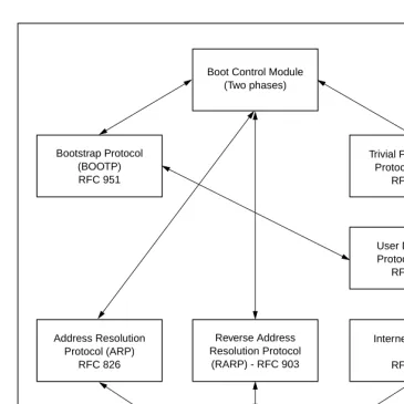
Figure 1-1 depicts the various modules (capabilities) and the dependencies of these modules that support the overall network boot function. They are described in the following paragraphs.
Intel 82596 LAN Coprocessor Ethernet Driver
This driver manages/surrounds the Intel 82596 LAN Coprocessor. Management is in the scope of the reception of packets, the
transmission of packets, receive buffer flushing, and interface initialization.
Figure 1-1. Network Boot Support Modules Boot Control Module
(Two phases)
Trivial File Transfer Protocol (TFTP)
RFC 783 Bootstrap Protocol
(BOOTP) RFC 951
User Datagram Protocol (UDP)
RFC 768
Internet Protocol (IP) RFC 791 Reverse Address
Resolution Protocol (RARP) - RFC 903 Address Resolution
Protocol (ARP) RFC 826
Ethernet Driver Intel 82596
Network I/O Support
1
UDP/IP Protocol Modules
The Internet Protocol (IP) is designed for use in interconnected systems of packet-switched computer communication networks. The Internet protocol provides for transmitting of blocks of data called datagrams (hence User Datagram Protocol, or UDP) from sources to destinations, where sources and destinations are hosts identified by fixed length addresses.
The UDP/IP protocols are necessary for the TFTP and BOOTP protocols; TFTP and BOOTP require a UDP/IP connection.
RARP/ARP Protocol Modules
The Reverse Address Resolution Protocol (RARP) basically consists of an identity-less node broadcasting a "whoami" packet onto the Ethernet, and waiting for an answer. The RARP server fills an Ethernet reply packet up with the target's Internet Address and sends it.
The Address Resolution Protocol (ARP) basically provides a method of converting protocol addresses (e.g., IP addresses) to local area network addresses (e.g., Ethernet addresses). The RARP protocol module supports systems which do not support the BOOTP protocol (next paragraph).
BOOTP Protocol Module
The Bootstrap Protocol (BOOTP) basically allows a diskless client machine to discover its own IP address, the address of a server host, and the name of a file to be loaded into memory and executed.
TFTP Protocol Module
files between machines on different networks implementing UDP. The only thing it can do is read and write files from/to a remote server.
Network Boot Control Module
The "control" capability of the Network Boot Control Module ties together all the modules (capabilities) and determines the booting sequence. The booting sequence has two phases: the first, labeled "address determination and bootfile selection", uses RARP/BOOTP and the second, labeled "file transfer", uses TFTP.
Network I/O Error Codes
16XBug returns an error code if an attempted network operation is unsuccessful. Refer to Appendix H for an explanation of network I/O error codes.
Multiprocessor Support
The MVME16X dual-port RAM feature makes the shared RAM available to remote processors as well as to the local processor. You can access it by either the MPCR or GCSR method, which are described in the next subsections. Either method can be enabled or disabled by the ENV command as its Remote Start Switch Method.
Multiprocessor Control Register (MPCR) Method
Multiprocessor Support
1
the debugger loads it at, contains one of two longwords used to control communication between processors. Organization of the MPCR contents is:
The status codes stored in the MPCR are of two types:
❏ Status returned (from the monitor)
❏ Status set (by the bus master)
The status codes that may be returned from the monitor are:
You can only program FLASH memory by the MPCR method. See the .PFLASH system call for a description of the FLASH memory program control packet structure.
The status codes that may be set by the bus master are:
The Multiprocessor Address Register (MPAR), located in shared RAM location of $804 offset from the base address the debugger loads it at, contains the second of two longwords used to control
$800 * N/A N/A N/A (MPCR)
Hex 0 (Hex 00) Wait. Initialization not yet complete. ASCII E (Hex 45) Code pointed to by the MPAR address
is executing.
ASCII P (Hex 50) Program FLASH Memory. The MPAR is set to the address of the FLASH memory program control packet. ASCII R (Hex 52) Ready. The Þrmware monitor is
watching for a change.
ASCII G (Hex 47) Use Go Direct (GD) logic specifying the MPAR address.
communication between processors. The MPAR contents specify the address at which execution for the remote processor is to begin if the MPCR contains a G or B. The MPAR is organized as follows:
At power-up, the debug monitor self-test routines initialize RAM, including the memory locations used for multi-processor support ($800 through $807).
The MPCR contains $00 at power-up, indicating that initialization is not yet complete. As the initialization proceeds, the execution path comes to the "prompt" routine. Before sending the prompt, this routine places an R in the MPCR to indicate that initialization is complete. Then the prompt is sent.
If no terminal is connected to the port, the MPCR is still polled to see whether an external processor requires control to be passed to the dual-port RAM. If a terminal does respond, the MPCR is polled for the same purpose while the serial port is being polled for user input.
An ASCII G placed in the MPCR by a remote processor requests a Go Direct type of transfer; an ASCII B indicates that breakpoints are to be armed before control is transferred (like the GO command).
In either sequence, an E is placed in the MPCR to indicate that execution is underway just before control is passed to RAM. (Any remote processor could examine the MPCR contents.)
If the code being executed in dual-port RAM is to reenter the debug monitor, a TRAP #15 call using function $0063 (SYSCALL
.RETURN) returns control to the monitor with a new display prompt. Note that every time the debug monitor returns to the prompt, an R is moved into the MPCR to indicate that control can be transferred once again to a specified RAM location.
Diagnostic Facilities
1
GCSR Method
A remote processor can initiate program execution in the local MVME16X dual-port RAM by issuing a remote GO command using the VMEchip2 Global Control and Status Registers (GCSR). The remote processor places the MVME16X execution address in general purpose registers 0 and 1 (GPCSR0 and GPCSR1). The remote processor then sets bit 8 (SIG0) of the VMEchip2 LM/SIG register. This causes the MVME16X to install breakpoints and begin execution. The result is identical to the MPCR method (with status code B) described in the previous section.
The GCSR registers are accessed in the VMEbus short I/O space. Each general purpose register is two bytes wide, occurring at an even address. The general purpose register number 0 is at an offset of $8 (local bus) or $4 (VMEbus) from the start of the GCSR
registers. The local bus base address for the GCSR is $FFF40100. The VMEbus base address for the GCSR depends on the group select value and the board select value programmed in the Local Control and Status Registers (LCSR) of the MVME16X. The execution address is formed by reading the GCSR general purpose registers in the following manner:
The address appears as:
Diagnostic Facilities
Included in the 16XBug package is a complete set of hardware diagnostics intended for testing and troubleshooting of the MVME16X. These diagnostics are completely described in each board-specific debugger or diagnostics manual (refer to the Related
GPCSR0 Used as the upper 16 bits of the address GPCSR1 Used as the lower 16 bits of the address
In order to use the diagnostics, you must switch directories to the diagnostic directory. If you are in the debugger directory, you can switch to the diagnostic directory by entering the debugger command Switch Directories (SD). The diagnostic prompt (" 16X-Diag>") should appear. Refer to the board-specific debugger manual
for complete descriptions of the diagnostic routines available and instructions on how to invoke them.
2
2
Using the 16XBug Debugger
Entering Debugger Command Lines
16XBug is command-driven and performs its various operations in response to user commands entered at the keyboard. When the debugger prompt (16X-Bug>) appears on the terminal screen, then
the debugger is ready to accept commands.
As the command line is entered, it is stored in an internal buffer. Execution begins only after the carriage return is entered, so that you can correct entry errors, if necessary, using the control characters described in Chapter 1.
When a command is entered, the debugger executes the command and the prompt reappears. However, if the command entered causes execution of user target code, for example GO, then control may or may not return to the debugger, depending on what the user program does. For example, if a breakpoint has been specified, then control returns to the debugger when the breakpoint is encountered during execution of the user program. Alternately, the user program could return to the debugger by means of the TRAP #15 function ".RETURN" (described in Chapter 5). For more about this, refer to the descriptions in Chapter 3 for the GD, GT, and GO commands.
The Command Line
In general, a debugger command is made up of the following parts:
❏ The command identifier (e.g., MD or md for the Memory Display command). Note that either upper- or lowercase is allowed.
2
❏ Any required arguments, as specified by the command.❏ An option field, set off by a semicolon (;), to specify
conditions other than the default conditions of the command.
The commands are shown using a modified Backus-Naur form syntax. The metasymbols used are:
Command Arguments
The following command arguments are encountered in the command descriptions which follow. Additional command arguments may be used and are defined in the particular command description in which they occur.
A delimiter is required between arguments. This may be either a space or a comma. To use the default value for an argument before specifying a subsequent argument, you must insert commas as delimiters.
boldface strings A boldface string is a literal such as a command or a program name, and is to be typed just as it appears.
italic strings An italic string is a "syntactic variableÓ and is to be replaced by one of a class of items it represents.
| A vertical bar separating two or more items
indicates that a choice is to be made; only one of the items separated by this symbol should be selected.
[ ] Square brackets enclose an item that is optional. The item may appear zero or one time.
{ } Braces enclose an optional symbol that may occur zero or more times.
exp Expression (described in detail in a following section).
address Address (described in detail in a following section).
count Count; the syntax is the same as for exp.
range A range of memory addresses which may be speciÞed either by address address or by address : count.
Entering Debugger Command Lines
2
exp - Expression as a ParameterAn expression (exp) can be one or more numeric values separated by the arithmetic operators: plus (+), minus (-), multiplied by (*), divided by (/), logical AND (&), shift left (<<), or shift right (>>).
Numeric values may be expressed in either hexadecimal, decimal, octal, or binary by immediately preceding them with the proper base identifier.
If no base identifier is specified, then the numeric value is assumed to be hexadecimal.
A numeric value may also be expressed as a string literal of up to four characters. The string literal must begin and end with the single quote mark ('). The numeric value is interpreted as the concatenation of the ASCII values of the characters. This value is right-justified, as any other numeric value would be.
Evaluation of an expression is always from left to right unless parentheses are used to group part of the expression. There is no operator precedence. Subexpressions within parentheses are
Data Type Base IdentiÞer Examples
Integer Hexadecimal $ $FFFFFFFF Integer Decimal & &1974, &10-&4 Integer Octal @ @456
Integer Binary % %1000110
String Literal Numeric Value (In Hexadecimal)
'A' 41
2
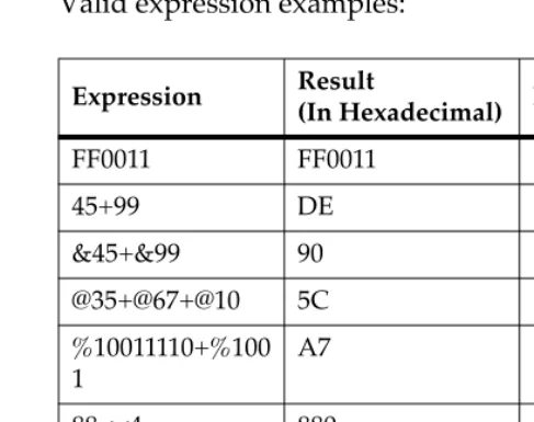
Valid expression examples:The total value of the expression must be between 0 and $FFFFFFFF.
address - Address as a Parameter
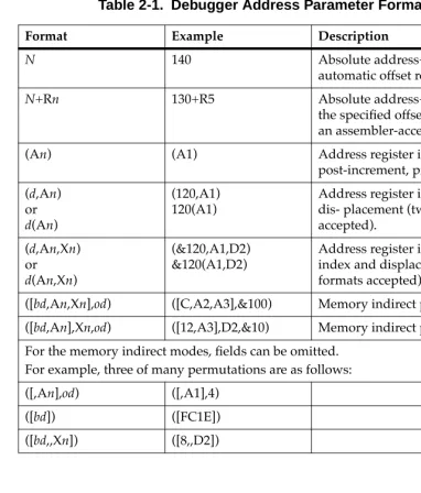
Many commands use address as a parameter. The syntax accepted by 16XBug is similar to the one accepted by the MC68040/MC68040 one-line assembler. All control addressing modes are allowed. An "address + offset register" mode is also provided.
Table 2-1 summarizes the address formats which are acceptable for address parameters in debugger command lines.
Expression Result
(In Hexadecimal) Notes
FF0011 FF0011
45+99 DE
&45+&99 90 @35+@67+@10 5C %10011110+%100 1
A7
88<<4 880 shift left AA&F0 A0 logical
2
Note In commands with and with size option W or L chosen, data at the second range specified as address address, (ending) address is acted on only if the second address is a proper boundary for a word or longword,respectively.
Offset Registers
Eight pseudo-registers (R0 through R7) called offset registers are used to simplify the debugging of relocatable and
position-independent modules. The listing files in these types of programs usually start at an address (normally 0) that is not the one at which they are loaded, so it is harder to correlate addresses in the listing with addresses in the loaded program. The offset registers solve this problem by taking into account this difference and forcing the display of addresses in a relative address+offset format. Offset registers have adjustable ranges and may even have overlapping ranges. The range for each offset register is set by two addresses: base and top. Specifying the base and top addresses for an offset register sets its range. In the event that an address falls in two or more offset registers' ranges, the one that yields the least offset is chosen.
Note Relative addresses are limited to 1MB (5 digits), regardless of the range of the closest offset register.
Example
Entering Debugger Command Lines
2
12 *
3 * MOVE STRING SUBROUTINE 4 *
5 0 00000000 48E78080 MOVESTR MOVEM.L D0/A0,—(A7) 6 0 00000004 4280 CLR.L D0
7 0 00000006 1018 MOVE.B (A0)+,D0 8 0 00000008 5340 SUBQ.W #1,D0 9 0 0000000A 12D8 LOOP MOVE.B (A0)+,(A1)+ 10 0 0000000C 51C8FFFC MOVS DBRA D0,LOOP 11 0 00000010 4CDF0101 MOVEM.L (A7)+,D0/A0 12 0 00000014 4E75 RTS
13
14 END ****** TOTAL ERRORS 0——
****** TOTAL WARNINGS 0——
The above program was loaded at address $0001327C.
The disassembled code is shown next:
167Bug>MD 1327C;DI
0001327C 48E78080 MOVEM.L D0/A0,—(A7) 00013280 4280 CLR.L D0
00013282 1018 MOVE.B (A0)+,D0 00013284 5340 SUBQ.W #1,D0 00013286 12D8 MOVE.B (A0)+,(A1)+ 00013288 51C8FFFC DBF D0,$13286 0001328C 4CDF0101 MOVEM.L (A7)+,D0/A0 00013290 4E75 RTS
167Bug>
By using one of the offset registers, the disassembled code
2
167Bug>OF R0R0 =00000000 00000000? 1327C. <CR> 167Bug>MD 0+R0;DI <CR>
00000+R0 48E78080 MOVEM.L D0/A0,—(A7) 00004+R0 4280 CLR.L D0
00006+R0 1018 MOVE.B (A0)+,D0 00008+R0 5340 SUBQ.W #1,D0 0000A+R0 12D8 MOVE.B (A0)+,(A1)+ 0000C+R0 51C8FFFC DBF D0,$A+R0 00010+R0 4CDF0101 MOVEM.L (A7)+,D0/A0 00014+R0 4E75 RTS
167Bug>
For additional information about the offset registers, refer to the OF command description.
Port Numbers
Some 16XBug commands give you the option to choose the port to be used to input or output. Refer to the board installation manual for port information.
Entering and Debugging Programs
There are various ways to enter a user program into system memory for execution. One way is to create the program using the Memory Modify (MM) command with the assembler/
disassembler option. You enter the program one source line at a time. After each source line is entered, it is assembled and the object code is loaded to memory. Refer to Chapter 4 for complete details of the 16XBug Assembler/Disassembler.
Another way to enter a program is to download an object file from a host system. The program must be in S-record format (described in Appendix C) and may have been assembled or compiled on the host system. Alternately, the program may have been previously created using the 16XBug MM command as outlined above and stored to the host using the Dump (DU) command. A
Calling System Utilities from User Programs
2
MVME16X port 1. (Hardware configuration details are in thesection on Installation and Startup in Chapter 1.) The file is
downloaded from the host to MVME16X memory by the Load (LO) command.
Another way is by reading in the program from disk, using one of the disk commands (BO, BH, IOP). Once the object code has been loaded into memory, you can set breakpoints if desired and run the code or trace through it.
Yet another way is via the network, using one of the network disk commands (NBO, NBH, NIOP).
Calling System Utilities from User Programs
A convenient way of doing character input/output and many other useful operations has been provided so that you do not have to write these routines into the target code. You can access various 16XBug routines via one of the MC68040 and MC68060 TRAP instructions, using vector #15. Refer to Chapter 5 for details on the various TRAP #15 utilities available and how to invoke them from within a user program.
Preserving the Debugger Operating
Environment
This section explains how to avoid contaminating the operating environment of the debugger. 16XBug uses certain of the
MVME16X onboard resources and also offboard system memory to contain temporary variables, exception vectors, etc. If you disturb resources upon which 16XBug depends, then the debugger may function unreliably or not at all.
2
translation tables for the debugger to have access to its various resources. The debugger honors the enabling of the MMUs; it does not disable translation.16XBug Vector Table and Workspace
As described in the Memory Requirements section in Chapter 1, 16XBug needs 64KB of read/write memory to operate. The 16XBug reserves a 1024-byte area for a user program vector table area and then allocates another 1024-byte area and builds an exception vector table for the debugger itself to use. Next, 16XBug reserves space for static variables and initializes these static variables to predefined default values. After the static variables, 16XBug allocates space for the system stack, then initializes the system stack pointer to the top of this area.
With the exception of the first 1024-byte vector table area, you must be extremely careful not to use the above-mentioned memory areas for other purposes. You should refer to the Memory Requirements section in Chapter 1 and to Appendix A to determine how to dictate the location of the reserved memory areas. If, for example, your program inadvertently wrote over the static variable area
containing the serial communication parameters, these parameters would be lost, resulting in a loss of communication with the system console terminal. If your program corrupts the system stack, then an incorrect value may be loaded into the processor Program Counter (PC), causing a system crash.
Hardware Functions
Preserving the Debugger Operating Environment
2
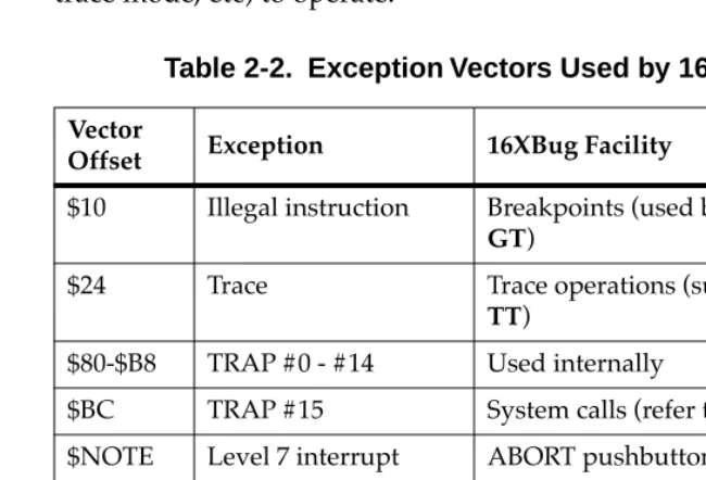
Exception Vectors Used by 16XBug
The exception vectors used by the debugger are listed below. These vectors must reside at the specified offsets in the target program's vector table for the associated debugger facilities (breakpoints, trace mode, etc) to operate.
When the debugger handles any exception, the target stack pointer is left pointing past the bottom of the exception stack frame created; that is, it reflects the system stack pointer values just before the
Table 2-2. Exception Vectors Used by 16XBug
Vector
Offset Exception 16XBug Facility
$10 Illegal instruction Breakpoints (used by GO, GN,
GT)
$24 Trace Trace operations (such as T, TC,
TT)
$80-$B8 TRAP #0 - #14 Used internally
$BC TRAP #15 System calls (refer to Chapter 5) $NOTE Level 7 interrupt ABORT pushbutton
$NOTE Level 7 interrupt AC Fail $DC FP Unimplemented
Data Type
Software emulation and data type conversion of ßoating point data.
Note This depends on what the Vector Base Register (VBR) is set to in the MCchip.
Preserving the Debugger Operating Environment
2
The 16XBug initializes the target vector table with the debuggervectors listed in Table 2-2 and fills the other vector locations with the address of a generalized exception handler. The target program may take over as many vectors as desired by simply writing its own exception vectors into the table. If the vector locations listed in Table 2-2 are overwritten then the accompanying debugger functions are lost.
The 16XBug maintains a separate vector table for its own use. In general, you do not have to be aware of the existence of the
debugger vector table. It is completely transparent and you should never make any modifications to the vectors contained in it.
Creating a New Vector Table
Your program may create a separate vector table in memory to contain its exception vectors. If this is done, the program must change the value of the VBR to point at the new vector table. In order to use the debugger facilities you can copy the proper vectors from the 16XBug vector table into the corresponding vector locations in your program vector table.
The vector for the 16XBug generalized exception handler may be copied from offset $08 (bus error vector) in the target vector table to all locations in your program vector table where a separate
exception handler is not used. This provides diagnostic support in the event that your program is stopped by an unexpected
exception. The generalized exception handler gives a formatted display of the target registers and identifies the type of the exception.
2
When entering data in single or double precision format, the following rules must be observed:1. The sign field is the first field and is a binary field.
2. The exponent field is the second field and is a hexadecimal field.
3. The mantissa field is the last field and is a hexadecimal field.
4. The sign field, the exponent field, and at least the first digit of the mantissa field must be present (any unspecified digits in the mantissa field are set to zero).
5. Each field must be separated from adjacent fields by an underscore.
6. All the digit positions in the sign and exponent fields must be present.
Single Precision Real
This format would appear in memory as:
A single precision number takes 4 bytes in memory.
Double Precision Real
This format would appear in memory as:
A double precision number takes 8 bytes in memory.
1-bit sign Þeld (1 binary digit)
8-bit biased exponent Þeld (2 hex digits. Bias = $7F) 23-bit fraction Þeld (6 hex digits)
1-bit sign Þeld (1 binary digit)
Floating Point Support
2
Notes 1. The single and double precision formats have animplied integer bit (always 1).
2. The 68K debuggers do NOT support extended (X) display options such as extended precision format (;X) or packed decimal format (;P). If you attempt to use these formats, the debugger will return an **** Illegal
Option **** error message.
Scientific Notation
This format provides a convenient way to enter and display a floating point decimal number. Internally, the number is assembled into a packed decimal number and then converted into a number of the specified data type.
Entering data in this format requires the following fields: ❏ A sign bit (+ or -); if omitted, default is +.
❏ One decimal digit followed by a decimal point.
❏ Up to 17 decimal digits (at least one must be entered).
❏ An optional Exponent field that consists of:
Ð An optional underscore.
Ð The Exponent field identifier, letter "E". Ð An optional Exponent sign (+, -). Ð From 1 to 3 decimal digits.
For more information about the floating point unit of the MC68040 and MC68060 microprocessors, refer to the appropriate
3
3
Debugger Commands
Introduction
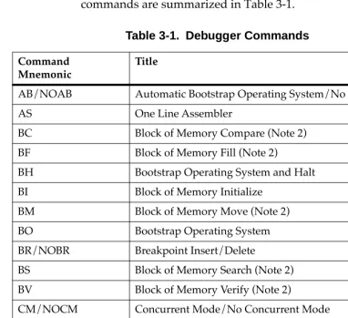
This chapter contains descriptions of each debugger command, with one or more examples of each. The 16XBug debugger commands are summarized in Table 3-1.
Table 3-1. Debugger Commands
Command Mnemonic
Title
AB/NOAB Automatic Bootstrap Operating System/No Autoboot AS One Line Assembler
BC Block of Memory Compare (Note 2) BF Block of Memory Fill (Note 2)
BH Bootstrap Operating System and Halt BI Block of Memory Initialize
BM Block of Memory Move (Note 2) BO Bootstrap Operating System BR/NOBR Breakpoint Insert/Delete
BS Block of Memory Search (Note 2) BV Block of Memory Verify (Note 2)
CM/NOCM Concurrent Mode/No Concurrent Mode CNFG ConÞgure Board Information Block CS Checksum (Note 2)
3
DU Dump S-Records ECHO Echo String
ENV Set Environment to Bug/Operating System GD Go Direct (Ignore Breakpoints)
GN Go to Next Instruction GO Go Execute User Program GT Go to Temporary Breakpoint HE Help (NOTE 2)
IOC I/O Control for Disk IOI I/O Inquiry
IOP I/O Physical (Direct Disk Access) (Note 2)
IOT I/O Teach for ConÞguring Disk Controller (Note 2) IRQM Interrupt Request Mask
LO Load S-Records from Host (Note 2) MA/NOMA Macro DeÞne/Display/Delete MAE Macro Edit
MAL/NOMAL Enable/Disable Macro Expansion Listing MAR Load Macros
MAW Save Macros
MD Memory Display (Note 2) MENU System Menu
MM Memory Modify (Note 2) MMD Memory Map Diagnostic MS Memory Set (Note 2) MW Memory Write
Table 3-1. Debugger Commands (Continued)
Command Mnemonic
Introduction
3
NAB Automatic Network Boot Operating System NBH Network Boot Operating System and Halt NBO Network Boot Operating System
NIOC Network I/O Control
NIOP Network I/O Physical (Note 2) NIOT Network I/O Teach (Note 2) NPING Network Ping
OF Offset Registers Display/Modify PA/NOPA Printer Attach/Detach
PF/NOPF Port Format/Detach (Note 2) PFLASH Program FLASH Memory (Note 2)
PS Put RTC into Power Save Mode for Storage RB/NORB ROMboot Enable/Disable
RD Register Display
REMOTE Connect Remote Modem to CSO RESET Cold/Warm Reset
RL Read Loop
RM Register Modify RS Register Set SD Switch Directories
SET Set Time and Date (Note 2) SYM/NOSYM Symbol Table Attach/Detach SYMS Symbol Table Display/Search
T Trace
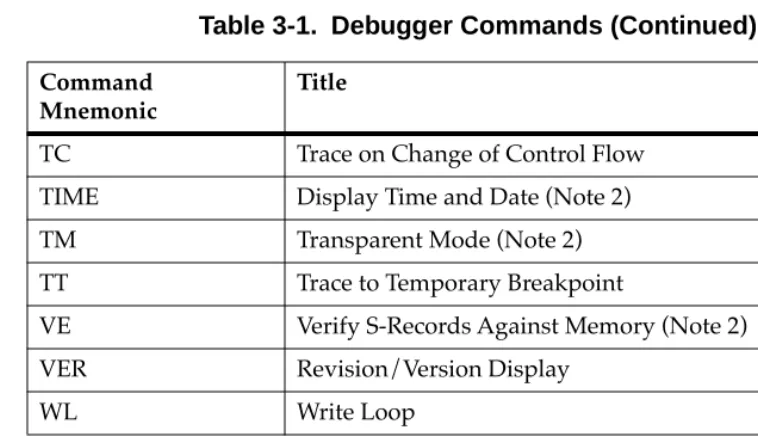
Table 3-1. Debugger Commands (Continued)
Command Mnemonic
3
Each of the individual commands is described in the following pages. The command syntax is shown using the symbols explained in Chapter 2.
In the examples shown, the symbol <CR> represents the carriage Return or Enter key on your terminal keyboard. Whenever this symbol appears, it means that you should enter a carriage return.
TC Trace on Change of Control Flow TIME Display Time and Date (Note 2) TM Transparent Mode (Note 2) TT Trace to Temporary Breakpoint
VE Verify S-Records Against Memory (Note 2) VER Revision/Version Display
WL Write Loop
Notes 1. In most examples of commands and displays given in this manual, 167Bug is used. However, the commands, displays, and system calls apply to all 68K CISC debugging packages, unless otherwise noted. 2. These commands are also part of the reduced command set
contained in the BootBug PROM for boards that have a BootBug function.
Table 3-1. Debugger Commands (Continued)
Command Mnemonic
AB/NOAB - Automatic Bootstrap Operating System/No Autoboot
3
AB/NOAB - Automatic Bootstrap Operating
System/No Autoboot
Command Input
AB [;V] NOAB
Description
The AB command re-invokes the autoboot sequence.
The option field V (verbose) enables the autoboot sequence to display the controller and device numbers while it is scanning as well as the returned packet status.
The NOAB command disables the automatic boot function.
Examples
167-Bug>AB Enables the autoboot function.
167-Bug>NOAB Disables the autoboot function but
3
AS - One Line Assembler
Command Input
AS address Description
BC - Block of Memory Compare
3
BC - Block of Memory Compare
Command Input
BC range address [; B|W|L] Options
B Byte
W Word (default)
L Longword
Description
The BC command compares the contents of memory defined by range with another place in memory, beginning at address.
The option field B, W, or L (upper- or lowercase) defines the size of data compared, and also, if range is specified using a count, defines the size of data element to which the count refers. For example, a count of 4 with an option of L would mean to compare 4 longwords (16 bytes).
If the range beginning address is greater than or equal to the end address, an error message is displayed and no comparison takes place.
For the following examples, assume that memory blocks 20000-20020 and 21000-21020 contain identical data.
Example 1: Memory compare, nothing printed.
167-Bug>BC 20000 2001F 21000
Effective address: 00020000
Effective address: 0002001F
Effective address: 00021000
3
Example 2: Memory compare, nothing printed.
167-Bug>BC 20000:20 21000;B
Effective address: 00020000
Effective count : &32
Effective address: 00021000
167-Bug>
Example 3: Create a mismatch.
167-Bug>MM 2100F;B
0002100F 21? 0.
167-Bug>
167-Bug>BC 20000:20 21000;B
Effective address: 00020000
Effective count : &32
Effective address: 00021000
0002000F|21 0002100F|00
BF - Block of Memory Fill
3
BF - Block of Memory Fill
Command Input
BF range data [increment] [; B|W|L] Arguments
data and increment are both expression parameters. Options
B Byte
W Word (default)
L Longword
Description
The BF command fills the specified range of memory with a data pattern. If an increment is specified, then data is incremented by this value following each write, otherwise data remains a constant value. A decrementing pattern may be accomplished by entering a negative increment. The data that you enter is right-justified in either a byte, word, or longword field (as specified by the option selected).
If the user-entered data does not fit into the data field size, then leading bits are truncated to make it fit. If truncation occurs, then a message is printed stating the data pattern which was actually written (or initially written if an increment was specified).
If the user-entered increment does not fit into the data field size, then leading bits are truncated to make it fit. If truncation occurs, then a message is printed stating the increment which was actually used.
3
specified range is ever disturbed in any case. The "Effective address" messages displayed by the command show exactly where data was stored.
Example 1
Assume memory from $20000 through $2002F is clear.
167-Bug>BF 20000,2001F 4E71 <CR>
Effective address: 00020000
Effective address: 0002001F
167-Bug>MD 20000:18;W <CR>
00020000 4E71 4E71 4E71 4E71 4E71 4E71 4E71
4E71 NqNqNqNqNqNqNqNq
00020010 4E71 4E71 4E71 4E71 4E71 4E71 4E71
4E71 NqNqNqNqNqNqNqNq
00020020 0000 0000 0000 0000 0000 0000 0000
0000 ...
Because no option was specified, the length of the data field defaulted to word.
Example 2
Assume memory from $20000 through $2002F is clear.
167-Bug>BF 20000:10 4E71 ;B <CR>
Effective address: 00020000
Effective count : &16
Data = $71
167-Bug>MD 20000:18 <CR>
00020000 7171 7171 7171 7171 7171 7171 7171
7171 qqqqqqqqqqqqqqqq
00020010 0000 0000 0000 0000 0000 0000 0000
0000 ...
00020020 0000 0000 0000 0000 0000 0000 0000
0000 ...
BF - Block of Memory Fill
3
Example 3Assume memory from $20000 through $2002F is clear.
167-Bug>BF 20000,20006 12345678 ;L <CR>
Effective address: 00020000
Effective address: 00020003
167-Bug>MD 20000:18 <CR>
00020000 1234 5678 0000 0000 0000 0000 0000
0000 .4Vx...
00020010 0000 0000 0000 0000 0000 0000 0000
0000 ...
00020020 0000 0000 0000 0000 0000 0000 0000
0000 ...
The longword pattern would not fit evenly in the given range. Only one longword was written and the "Effective address" messages reflect the fact that data was not written all the way up to the specified address.
Example 4
Assume memory from $20000 through $2002F is clear.
167-Bug>BF 20000:18 0 1 ;W<CR>
Effective address: 00020000
Effective count : &48
167-Bug>MD 20000:18 <CR>
00020000 0000 0001 0002 0003 0004 0005 0006
0007 ...
00020010 0008 0009 000A 000B 000C 000D 000E
000F ...
00020020 0010 0011 0012 0013 0014 0015 0016
3
BH - Bootstrap Operating System and Halt
Command Input
BH [controllerLUN] [deviceLUN] [string] Arguments
controllerLUN is the Logical Unit Number (LUN) of the controller to which the following device is attached. Defaults to LUN 0.
deviceLUN is the LUN of the device from which to boot. Defaults to LUN 0.
string is a string that is passed to the operating system or control program loaded. Its syntax and use is completely defined by the loaded program.
Description
BH is used to load an operating system or control program from disk into memory. This command works in exactly the same way as the BO command, except that control is not given to the loaded program. After the registers are initialized, control is returned to the 16XBug debugger and the prompt reappears on the terminal screen. Because control is retained by 16XBug, all the 16XBug facilities are available for debugging the loaded program if necessary.
A device probe with entry into the device descriptor table is done whenever a specified device is accessed via BH.
BH - Bootstrap Operating System and Halt
3
Example 1:167-Bug>bh 4,1 <CR> Boot and halt from Controller LUN 4,
Device LUN 0.
Booting from: VME350, Controller 4, Drive 0 Loading: Operating System
Volume: V/68
IPL loaded at: $00010000 167-Bug>
Example 2
167-Bug>bh 4,0,test167 <CR> Boot and halt from Controller LUN
4, Device LUN 0, and pass the string "test167" to the loaded program.
Booting from: VME350, Controller 4, Drive 0 Loading: test167
Volume: V/68
IPL loaded at: $00010000 167-Bug>
3
BI - Block of Memory Initialize
Command Input
BI range [;B|W|L] Options
B Byte
W Word (default)
L Longword
Description
The BI comman